IR2DWW6361Soil Moisture Station, 6361
Davis Instruments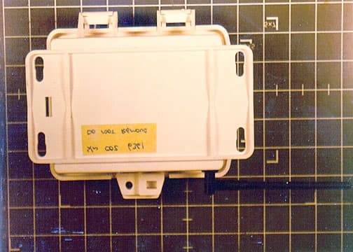
Click to zoom
Application Details
- Equipment Class
- DXX - Part 15 Low Power Communication Device Transmitter
- Date of Grant
- Aug 19, 2001
- Application Purpose
- Original Equipment
- Date of Application
- Aug 19, 2001
- Equipment Note
- Soil Moisture Station, 6361
- Frequency Range
- 916.00000000 - 916.00000000
- Company
- Davis Instruments
- Country
- United States
Documents & Files
Document Text
Text extracted from the exhibit documents filed with the FCC. Open a document above to read the original.
Users Manual
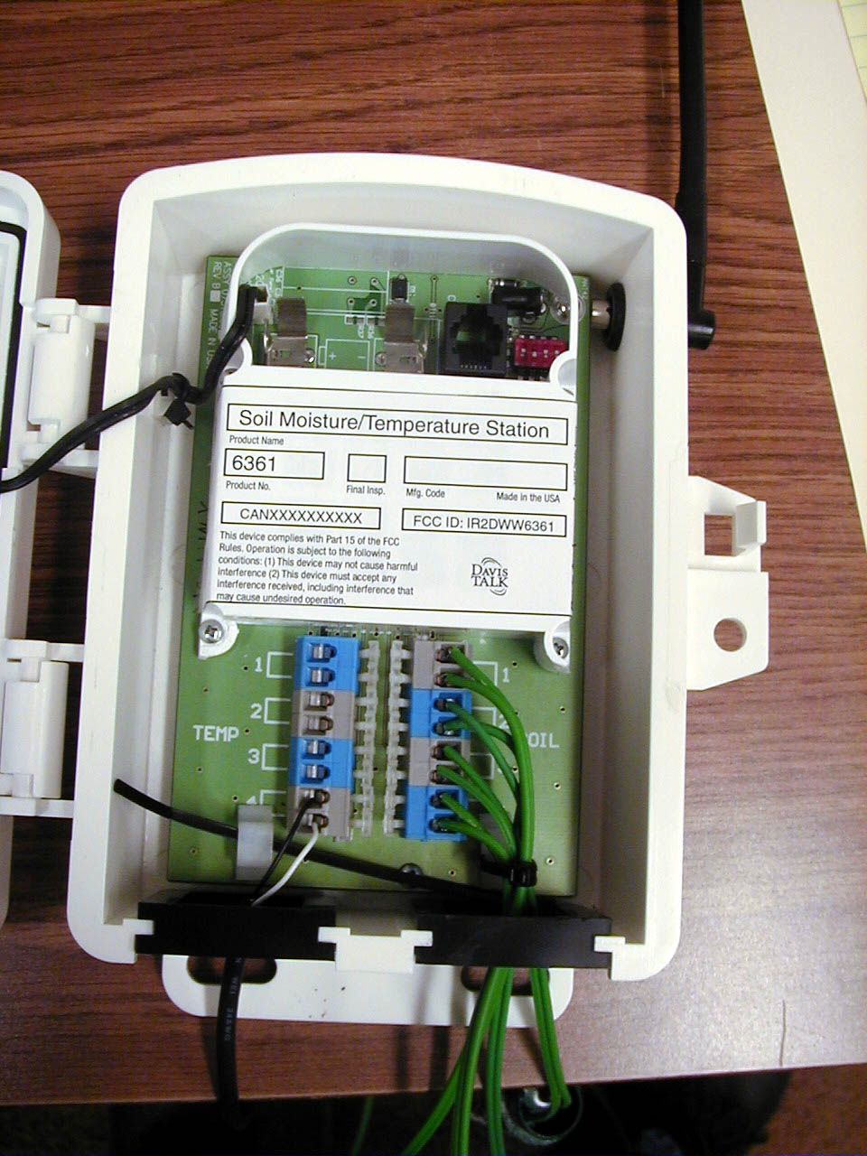
Product # 6361 W IRELESS S OIL M OISTURE / T EMPERATURE S TATION I NSTALLATION M ANUAL The Wireless Soil Moisture/Temperature Station, referred to in this document at the Soil Moisture Station, is for use with Wireless Vantage Pro TM Weather Sta- tions. Components The Soil Moisture Station includes the following components and mounting hardware: Soil Moisture Sensor with 15" (4.6 m) of cable Temperature Probe with 15" (4.6 m) of cable Shelter 3-Volt Lithium Battery 8" Cable Ties 4" Cable Ties Components Page 2Wireless Soil Moisture/ Temperature Station Tools for Setup In addition to the components shown, you will need some or all of the follow- ing materials: ✦ Adjustable wrench or 7/16" wrench ✦ Ballpoint pen or paper clip (small pointed object of some kind) ✦ Drill and 3/16" (5 mm) drill bit (if mounting on a vertical surface) ✦ Stepped Sensor Installation Tool Installation Steps For ease of installation, please follow steps in the order presented. ✦ Prepare the Soil Moisture station, page 3 ✦ Insert the battery, page 3 ✦ Set the transmitter ID, page 3 ✦ Set ID on the Soil Moisture Station using DIP switches, page 3 ✦ Set the console to recognize the signals, page 5 ✦ View current temperature, page 5 ✦ (If you don’t see temperature from the correct Station No., put the transmitter in TEST mode, page 5) ✦ Choose a location for the Soil Moisture Station, page 6 ✦ Test transmission from the proposed mounting location, page 7 ✦ Mount the Soil Moisture Station, page 8 ✦ A note on securing cables, page 10 For Technical Support, please see “Contacting Davis Technical Support” on page 10. 1/4" x 1-1/2" Lag Screws U-Bolts 1/4" Flat Washers 1/4" Lock Washers 1/4" Hex Nuts Mounting Hardware Preparing the Soil Moisture StationPage 3 Preparing the Soil Moisture Station The illustration below shows the location of the DavisTalk transmitter DIP Switches, the battery mounting location, and the terminal blocks used to connect the soil moisture sensors and temperature probes. Insert the 3-volt lithium battery into the battery holder, matching the “+” sign on the battery with the “+” sign on the SIM. Note the location of the DIP switches. You will work with them during the next installation step. Setting the Transmitter ID Each wireless transmitting station must be set to one of eight DavisTalk trans- mitter IDs. DIP switches #1, 2 and 3 on the SIM allow you to control the ID — the “channel” the station will transmit on. (DIP switch #4 is used for transmis- sion testing, not for transmitter ID.) A DavisTalk transmitter and receiver communicate with each other only when both are set to the same ID. 3-Volt Lithium Battery DIP Switches Terminal Blocks Sensor Interface Module on Soil Moisture Station Page 4Wireless Soil Moisture/ Temperature Station The factory default transmitter ID is ‘1’. Looking at the table below, you can see that means the DIP switches are in the OFF position when each transmitting station leaves the factory. This is true for all of Davis’ wireless equipment. The default setting on a Wireless Vantage Pro console is “ON (ISS).” The ISS is included with every Wireless Vantage Pro, so the console/receiver is set to find the ISS on DavisTalk channel 1. Verify the DavisTalk channel used by your ISS, as well as any other DavisTalk channels already in use by your Vantage Pro Weather Station Configure the Soil Moisture Station to a DavisTalk channel not already in use. Use a ballpoint pen or paper clip to toggle DIP switches #1, 2, and 3. The settings for transmitter IDs 1 – 8 are shown in the table below: Use this table to ensure that each wireless transmitting station in your system is broadcasting on its own transmitter ID. DIP Switches in Top-right Corner of SIM (Illustration has been enlarged for clarity) ID C ODE S WITCH 1S WITCH 2S WITCH 3 #1 (default) offoffoff #2offoffON #3offONoff #4offONON #5ONoffoff #6ONoffON #7ONONoff #8ONONON 1234 ON Battery Holder DIP Switches Setting the Transmitter IDPage 5 Setting Console/Receiver(s) to Same ID 1. Put your console into Setup Mode — press and hold the DONE key and press the DOWN arrow key. The console will show you Screen 1: Transmitters. You should see the words: “RECEIVING FROM...” and “STATION NO.” followed by the transmitter IDs that your console detects. One of these should be the ID number you just set on the Soil Moisture Station transmitter. If you don’t see it, make sure the console is within 10' of the transmitter, and verify that you set the DIP switches correctly. If you still don’t see it, go to “TEST mode” on the next page. 2. Press the DONE key to move on to Screen 2: Selecting Transmitters. Setup Mode – Screen 2 is where you will set the console to recognize signals on that ID as coming from a Soil Moisture Station. 3. Press the LEFT or RIGHT arrow key, or the STATION key, to scroll through transmitter IDs. When you see the ID you chose for the Soil Moisture Station, use the UP or DOWN arrow keys to activate reception of that ID code. Make sure the screen shows “ON”. 4. Press the GRAPH key to change the type of station assigned to that transmitter ID. Press the GRAPH key until the word “TEMP” appears. 5. To exit Setup Mode, press and hold the DONE key. (See the Vantage Pro User’s Manual & Setup Guide: “Setup Mode – Screen 2: Selecting Transmitters.”) Viewing Current Soil Moisture and Temperature Press the TEMP key until you see “SOIL MOIST” displayed on the console screen where the inside temperature is usually displayed. If you see SOIL MOIST and no number, you are seeing the moisture and temperature readings for sensor pair #1. If you continue to press the TEMP key, you will see the readings for sensor pairs #2, #3, and #4. If no sensors are installed the reading will be dashed out. This confirms communication between your Soil Moisture Station and the console — go on to “Choosing a Location for the Soil Moisture Station & Sensors” on page 6. If You Do Not See Current Values from the Correct Station No. First, verify that the…
Text truncated - open the document above for the full version.
Cover Letter(s)
Tuesday, August 14, 2001 Davis Instruments 3465 Diablo Ave. Hayward, CA 94545 Federal Communications Commission 7435 Oakland Mills Road Columbia, MD 21046 Gentlemen: This letter is to comply with Section 0.457(d)(2)(i) pertaining to confidential material. Davis Instruments would like the following documents regarding this submission for FCC ID: IR2DWW6361 to be kept confidential. 1. Soil Station Schematic.pdf" 2. “Soil Station Block Diagram.pdf” 3. "Expository Statement.doc" The above material contains trade secrets or technical data, which would customarily be guarded from competitors. We do not want these documents to be accessible to the general public. Sincerely, Brett Preston Director of Engineering
ID Label/Location Info
Wireless Soil Moisture/Temperature Station Size: 4.75” W x 1.75” H Material: vinyl Location: Inside the station's shelter protected from weather. The user will see the label when they install the station and during routine maintenance of the station. This device complies with Part 15 of the FCC Rules. Operation is subject to the following conditions: (1) This device may not cause harmful interference (2) This device must accept any interference received, including interference that may cause undesired operation. 3465 Diablo Avenue Hayward, CA 94545-2778 Mfg. Code Product Name Product No. Made in the USA Final Insp. Soil Moisture/Temperature Station 6361 FCC ID: IR2DWW6361 CANXXXXXXXXXX
Test Report
Page 1 of 36 Report No.: FC01-054A ADDENDUM TO FC01-054 FOR THE SOIL MOISTURE STATION, 6361 FCC PART 15 SUBPART C SECTIONS 15.249 & 15.207 COMPLIANCE DATE OF ISSUE: AUGUST 17, 2001 PREPARED FOR: Davis Instruments 3465 Diablo Avenue Hayward, CA 94545 PREPARED BY: Valerie Honsinger CKC Laboratories, Inc. 5473A Clouds Rest Mariposa, CA 95338 W.O. No.: 77339 Date of test: July 24 – August 3, 2001 Report No.: FC01-054A This report contains a total of 36 pages and may be reproduced in full only. Partial reproduction may only be done with the written consent of CKC Laboratories, Inc. Page 2 of 36 Report No.: FC01-054A TABLE OF CONTENTS Administrative Information............................................................................................. 4 Summary of Results ........................................................................................................ 5 Test Overview ................................................................................................................. 5 Modifications Required for Compliance......................................................................... 5 Approvals ........................................................................................................................ 5 Equipment Under Test (EUT) Description ..................................................................... 6 Equipment Under Test .................................................................................................... 6 Peripheral Devices........................................................................................................... 6 15.33 Frequency Range Tested ....................................................................................... 6 15.249 Radiated Emissions ................................................................................. 6 15.207 Conducted Emissions .............................................................................. 6 EUT Operating Frequency .............................................................................................. 6 Temperature and Humidity During Testing .................................................................... 6 Report of Measurements ................................................................................................. 7 Table 1: 15.249(a) - Fundamental Radiated Emission Levels ............................ 7 Table 2: 15.249/15.209 - Six Highest Radiated Emission Levels: 9kHz-1000MHz8 Table 3: 15.249/15.209 – Six Highest Radiated Emission Levels: 1-10GHz ..... 9 Table 4: 15.207 - Six Highest Conducted Emission Levels................................ 10 Measurement Uncertainty ............................................................................................... 11 EUT Setup .......................................................................................................................11 Correction Factors ........................................................................................................... 11 Table A: Sample Calculations............................................................................. 11 Test Instrumentation and Analyzer Settings ................................................................... 13 Table B: 15.35 Analyzer Bandwidth Settings Per Frequency Range ................. 13 Spectrum Analyzer Detector Functions .............................................................. 14 Peak ......................................................................................................... 14 Quasi-Peak .............................................................................................. 14 Average ................................................................................................... 14 EUT Testing ....................................................................................................................15 Radiated Emissions ............................................................................................. 15 Mains Conducted Emissions ............................................................................... 16 Transmitter Characteristics ............................................................................................. 16 15.203 Antenna Requirements ............................................................................ 16 15.205 Restricted Bands...................................................................................... 16 15.215 Additional Provisions to the General Radiated Emission Limitations.... 16 Appendix A : Setup Photographs .................................................................................... 17 Photograph Showing Radiated Emissions........................................................... 18 Page 3 of 36 Report No.: FC01-054A Photograph Showing Radiated Emissions........................................................... 19 Photograph Showing Mains Conducted Emissions ............................................ 20 Photograph Showing Radiated Emissions........................................................... 21 Appendix B: Test Equipment List................................................................................... 22 Appendix C: Measurement Data Sheets.......................................................................... 23 Fundamental Output Plot .................................................................................... 24 Bandedge Plot ..................................................................................................... 25 Test Data Sheets .................................................................................................. 26 Page 4 of 36 Report No.: FC01-054A CKC Laboratories, Inc. has received Certificates of Accreditation from the following agencies: A2LA (USA); DATech (Germany); BSMI (Taiwan); Nemko (Norway); and GOST (Russia). CKC Laboratories, Inc has received test site Registration Acceptance from the following agencies: …
Text truncated - open the document above for the full version.
Test Setup Photos
PHOTOGRAPH SHOWING RADIATED EMISSIONS Radiated Emissions - Front View PHOTOGRAPH SHOWING RADIATED EMISSIONS Radiated Emissions - Back View PHOTOGRAPH SHO WING MAINS CONDUCTED EMISSIONS Mains Conducted Emissions - Front View PHOTOGRAPH SHOWING RADIATED EMISSIONS Mains Conducted Emissions - Back View
Contact Information
Applicant
Bruce Walter(Sr Design Engineer)
Technical Contact
CKC Laboratories, Inc.Joyce Walker
[email protected]1-800-500-4362
5473A Clouds Rest · Mariposa, California · United States
Non-Technical Contact
CKC Laboratories, Inc.Joyce Walker
[email protected]1-800-500-4362
Test Firm
CKC Laboratories, Inc.Steve Behm
Technical Specifications
| # | Rule Parts | Frequency Range | Power Output |
|---|---|---|---|
| 1 | 15C | 916 MHz - 916 MHz | - |
Other Applications from Davis Instruments
IR2DWW6313U
Jan 03, 2023WeatherLink Console
Equipment Class
DTS - Digital Transmission System
IR2DWW765Y
Jun 09, 2005Vantage Pro 2 Wireless Repeater
Equipment Class
DSS - Part 15 Spread Spectrum Transmitter
IR2DWW6345
Mar 13, 2005Measurement Station
Equipment Class
DSS - Part 15 Spread Spectrum Transmitter
IR2DWW6312
Sep 29, 2004Integrated Vantage Pro 2 Console.
Equipment Class
DSS - Part 15 Spread Spectrum Transmitter
IR2DWW6328
Sep 29, 2004Integrated Sensor Suite 2 with SPARS
Equipment Class
DSS - Part 15 Spread Spectrum Transmitter