IR2DWW6320Integrated Sensor Suite, Model 6320W
Davis Instruments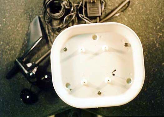
Click to zoom
Application Details
- Equipment Class
- DXX - Part 15 Low Power Communication Device Transmitter
- Date of Grant
- Nov 21, 1999
- Application Purpose
- Original Equipment
- Date of Application
- Aug 24, 1999
- Equipment Note
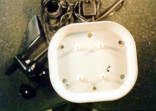
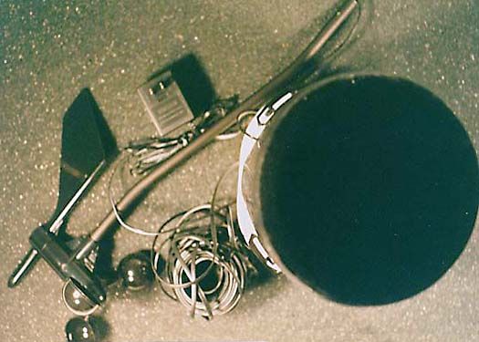
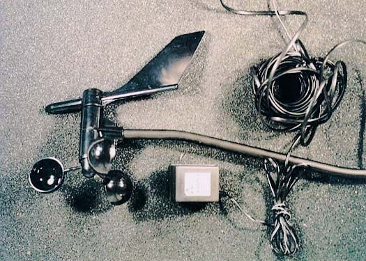
- Integrated Sensor Suite, Model 6320W
- Frequency Range
- 916.50000000 - 916.50000000
- Company
- Davis Instruments
- Country
- United States
Documents & Files
Document Text
Text extracted from the exhibit documents filed with the FCC. Open a document above to read the original.
Users Manual
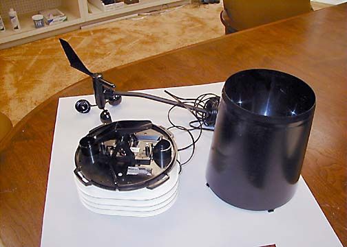
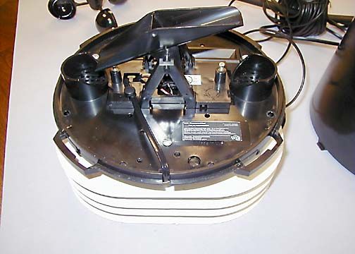
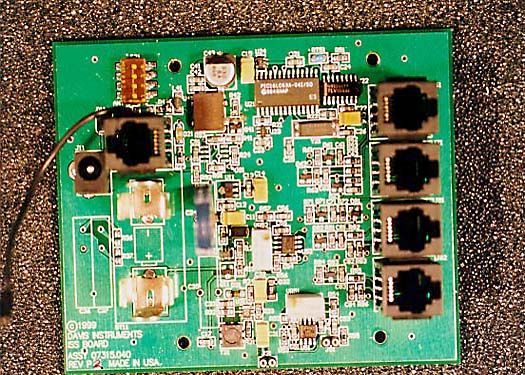
Product # 6320W I NTEGRATED S ENSOR S UITE I NSTALLATION M ANUAL The Integrated Sensor Suite (ISS) is an integrated, basically pre-assembled field station that collects data from attached sensors and then transmits it wirelessly, or via cable, to a console. The ISS standard complement of sensors includes: F Wind Speed F Wind Direction F Rainfall F Outside Temperature F Outside Humidity The Wireless ISS is user-configurable to communicate on one of 8 different ID codes. This allows multiple systems to coexist in the same geographical area. Note: The ISS operates on a low power frequency that does not require you to obtain an FCC license. T OOLS AND M ATERIALS N EEDED In addition to the components listed above, you may need some of the follow- ing tools and materials. F Phillips Screwdriver F Pencil or Other Pointed Object A SSEMBLING THE ISS To assemble the ISS, attach the anemometer arm to the field station assembly. Note: Alternatively, you can choose mount the anemometer separately from the ISS base. This option allows you to ensure clearance from possible airflow obstructions. Page 2Integrated Sensor Suite I NSTALLING THE ISS The instructions below will take you through the process required to install the wireless and wired sensor suite. Choosing a Location As you position your sensor suite, try to avoid possible obstructions of rain and wind—look out for trees and nearby buildings. If you have the wireless, solar-powered ISS look for spots with good exposure to the sun throughout the day. For roof mounting, and for ease of installation in other locations, we recom- mend using the optional Mounting Tripod (contact Davis for more informa- tion). Configuring the ISS F If you have a wired ISS, no configuration is necessary. F If you have a wireless ISS, the ISS’s transmitter must be setup so that it uses the same ID code as your console/receiver. For details on configuring the wireless ISS, see page 3. Applying Power to the ISS Apply power to the transmitter using one of the options indicated below. For all power options, Davis recommends using a backup battery to ensure power during storms. Insert a CR-123 3-volt lithium cell as a backup. F If you have a wireless system, plug the solar panel cord into the power jack on the board. The unit will operate off the day’s collected energy for up to 8 hours into the night. The remainder of the night, the unit will tap into the backup battery as a power source. Even so, the battery should last several years. F If you have a wired system, simply plug the ISS cable into the console. The console will provide any power needed by the ISS. Configuring the Wireless ISSPage 3 C ONFIGURING THE W IRELESS ISS Both the transmitter in the ISS and the receiver in the console have ID codes. These ID codes enable a specific transmitter to “talk to” a specific receiver, even if many transmitters are operating in the same area. Setting the ID Code The ISS may be set to use any of eight selectable ID codes (the default is ID Code #1). The ISS and console/receiver will only communicate with each other if they are both set to the same ID code. Use the default setting unless you have another Davis wireless weather station operating nearby which you want to work separately from the new system. The dip switch settings for the eight possible codes are shown below. To change to another ID, toggle dip switches 1, 2, and/or 3 on the ISS and then set the console/receiver’s ID code to match. Remember that the ISS and con- sole/receiver must use the same ID code in order to communicate. Note: Dip switch #4 is used for testing only, not for ID codes. See details below. Test Mode Dip switch #4 on the ISS allows you to configure the Test LED to flash when- ever a data packet is transmitted. This feature allows you to more easily set up and test your transmitting system. When you are done setting up or testing, however, make sure you turn dip switch #4 to OFF so that the LED does not flash and waste significant amounts of power unnecessarily . ID C ODE D IP S WITCH 1D IP S WITCH 2D IP S WITCH 3 #1 (default) offoffoff #2 offoffON #3 offONoff #4 offONON #5 ONoffoff #6 ONoffON #7 ONONoff #8 ONONON Product Numbers: 6150, 6150W, 6320 Davis Instruments Part Number: 7395 Integrated Sensor Suite Installation Manual Rev. A Manual (8/5/99) Controlled Online: Weather Manuals:DavisTalk:ISS © 1999 Davis Instruments Corp. All rights reserved. 3465 Diablo Avenue, Hayward, CA 94545-2778 510-732-9229 • Fax: 510-732-9118 E-mail: [email protected] • www.davisnet.com S PECIFICATIONS Transmit frequency: 916.5 MHz ID codes: 8 user-selectable License: Low power (less than 1 mW), no license required Temperature range: -40 to 60 °C Primary Power Input Options Console Power: Cable running from Vanguard Pro console Solar Power: Davis solar charger Secondary (Backup) Power: CR-123 3- volt lithium battery or equal FCC P ART 15 C LASS B R EGISTRATION W ARNING This equipment has been tested and found to comply with the limits for a class B digital device, pursuant to Part 15 of the FCC Rules. These limits are designed to provide reasonable protection against harmful interference in a residential installation. This equipment generates, uses and can radiate radio frequency energy and, if not installed and used in accordance with the instruc- tions, may cause harmful interference to radio communications. However, there is no guarantee that interference will not occur in a particular installation. If this equipment does cause harmful interference to radio or television recep- tion, which can be determined by turning the equipment off and on, the user is encouraged to try to correct the interference by one or more of the following measures: F Reorient or relocate the receiving antenna. F Increase the separation between the equipment and receiver. F Connect the equipment into an outlet on a circuit different from that to which the receiver is connected. F Consult the dealer or an experienced radio/TV technician for …
Text truncated - open the document above for the full version.
Cover Letter(s)
August 6, 1999 Davis Instruments 3465 Diablo Ave. Hayward, CA 94545 Federal Communications Commission 7435 Oakland Mills Road Columbia, MD 21046 Gentlemen: This is your letter of authorization to accept out appointment of CKC Laboratories, Inc. as Agent for Davis Instruments located in Hayward CA to sign applications before the Commission on our behalf, and to receive and exchange data between our company and the commission in connection with certification of the following Davis product: The device we are requesting certification for is our Integrated Sensor Suite (Product No. 6320W). The device is mounted outside a home and monitors the weather. In addition to reading it's analog and digital sensors, it transmits every 2.5 seconds a 6 byte packet of data to other receiving devices that are currently being developed by Davis Instruments. The transmitter is operating at 916.5 Mhz and uses less than 1 mW or power. Please send the FCC authorization to me, Brett Preston. We, the applicant certify that, in the case of individual applicant, he or she is not subject to a denial of federal benefits pursuant to section 5301 of the Anti-Drug Abuse Act of 1988, 21 USC 853a or in the case of non-individual applicant (e.g. corporation, partnership or other unincorporated association), no party to the applicant is subject to a denial of federal benefit pursuant to that action. This authorization will expire one year from the date of this letter. Sincerely, Brett Preston Director of Engineering
Cover Letter(s)
August 6, 1999 Davis Instruments 3465 Diablo Ave. Hayward, CA 94545 Federal Communications Commission 7435 Oakland Mills Road Columbia, MD 21046 Gentlemen: This letter is to comply with Section 0.457(d)(2)(i) pertaining to confidential material. Davis Instruments would like the following documents regarding this submission for FCC ID: IR2DWW6320 to be kept confidential. 1. "Circuit Diagram.pdf" 2. "Device Summary.doc" The above material contains trade secrets or technical data, which would customarily be guarded from competitors. We do not want these documents to be accessible to the general public. Sincerely, Brett Preston Director of Engineering
Test Report
Page 1 of 40 Report No: FC99-025 CERTIFICATION TEST REPORT FOR THE INTEGRATED SENSOR SUITE, 6320W FCC PART 15 SUBPART C COMPLIANCE DATE OF ISSUE: AUGUST 23, 1999 PREPARED FOR: Davis Instruments 3465 Diablo Ave. Hayward, CA 94545 P.O. No: 12542 W.O. No: 72312 PREPARED BY: Joyce Walker CKC Laboratories, Inc. 5473A Clouds Rest Mariposa, CA 95338 Date of test: August 6, 9, 16, 1999 Report No: FC99-025 DOCUMENTATION CONTROL: _____________________________ Tracy Phillips Documentation Control Supervisor CKC Laboratories, Inc. APPROVED BY: _____________________________ Dennis Ward Director of Laboratories CKC Laboratories, Inc. This report contains a total of 40 pages and may be reproduced in full only. Partial reproduction may only be done with the written consent of CKC Laboratories, Inc. Page 2 of 40 Report No: FC99-025 TABLE OF CONTENTS Administrative Information ............................................................................................. 3 Summary Of Results........................................................................................................ 5 Equipment Under Test (EUT) Description...................................................................... 5 Measurement Uncertainty................................................................................................ 5 EUT Operating Frequency............................................................................................... 5 Peripheral Devices ........................................................................................................... 5 Report Of Measurements................................................................................................. 6 Table 1: Six Highest Radiated Emission Levels-Below One GHz ..................... 6 Table 2: Six Highest Radiated Emission Levels - Above One GHz ................... 7 Table 3: Six Highest Conducted Emission Levels .............................................. 8 Table A : List Of Test Equipment ................................................................................... 9 EUT Setup .......................................................................................................................10 Test Instrumentation And Analyzer Settings................................................................... 11 Table B : Analyzer Bandwidth Settings Per Frequency Range........................... 11 Spectrum Analyzer Detector Functions............................................................... 12 Peak ......................................................................................................... 12 Quasi-Peak............................................................................................... 12 Average.................................................................................................... 12 Test Methods ...................................................................................................................13 Radiated Emissions Testing................................................................................. 13 Conducted Emissions Testing ............................................................................. 14 Occupied Bandwidth ........................................................................................... 14 Sample Calculations ........................................................................................................ 14 Appendix A : Information About The Equipment Under Test........................................ 16 I/O Ports............................................................................................................... 17 Crystal Oscillators ............................................................................................... 17 Printed Circuit Boards ......................................................................................... 17 Required EUT Changes To Comply.................................................................... 17 Cable Information................................................................................................ 18 Photograph Showing Radiated Emissions ........................................................... 19 Photograph Showing Radiated Emissions ........................................................... 20 Photograph Showing Conducted Emissions........................................................ 21 Photograph Showing Conducted Emissions........................................................ 22 Appendix B : Measurement Data Sheets ......................................................................... 23 Averaging for Pulsed Modulated Systems .......................................................... 24 Averaging for Pulsed Modulated Systems .......................................................... 25 Averaging for Pulsed Modulated Systems .......................................................... 26 Occupied Bandwidth Plot.................................................................................... 27 Occupied Bandwidth Plot.................................................................................... 28 Occupied Bandwidth Plot.................................................................................... 29 Occupied Bandwidth Plot.................................................................................... 30 Page 3 of 40 Report No: FC99-025 CKC Laboratories, Inc. has Certificates of Accreditation from the following agencies : DATech (Germany); A2LA (USA); FCC (USA); VCCI (Japan); BSMI (Taiwan); HOKLAS (Hong Kong). CKC Laboratories, Inc. has Letters of Acceptance through an MRA for the following agencies: ACA/NATA (Australia); SABS (South Africa); SWEDAC (Sweden); TUV Rheinland-Germany; TUV Rheinland- Korea; TUV Rheinland-Russia; Radio Communication Agency (RA); NEMKO (Norway). ADMINISTRATIVE INFORMATION DATE OF TEST: August 6, 9, 16, 1999 PURPOSE OF TEST: To demonstrate the compliance of the Integrated Sensor Suite, …
Text truncated - open the document above for the full version.
Contact Information
Applicant
Bruce Walter(Sr Design Engineer)
Technical Contact
CKC Laboratories, Inc.Tracy Phillips
[email protected]1-800-500-4362
5473A Clouds Rest · Mariposa, California · United States
Non-Technical Contact
CKC Laboratories, Inc.Joyce Walker
[email protected]1-800-500-4362
Test Firm
CKC Laboratories, Inc.Steve Behm
Technical Specifications
| # | Rule Parts | Frequency Range | Power Output |
|---|---|---|---|
| 1 | 15C | 916.5 MHz - 916.5 MHz | - |
Other Applications from Davis Instruments
IR2DWW6313U
Jan 03, 2023WeatherLink Console
Equipment Class
DTS - Digital Transmission System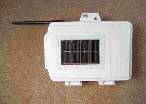
IR2DWW765Y
Jun 09, 2005Vantage Pro 2 Wireless Repeater
Equipment Class
DSS - Part 15 Spread Spectrum Transmitter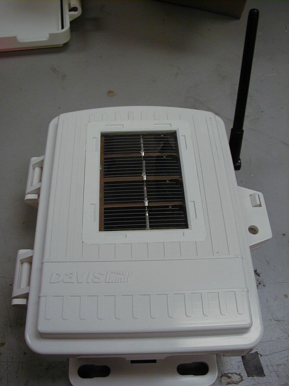
IR2DWW6345
Mar 13, 2005Measurement Station
Equipment Class
DSS - Part 15 Spread Spectrum Transmitter
IR2DWW6312
Sep 29, 2004Integrated Vantage Pro 2 Console.
Equipment Class
DSS - Part 15 Spread Spectrum Transmitter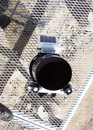
IR2DWW6328
Sep 29, 2004Integrated Sensor Suite 2 with SPARS
Equipment Class
DSS - Part 15 Spread Spectrum Transmitter