IR2DWW6326ISS PLUS
Davis Instruments
Click to zoom
Application Details
- Equipment Class
- DXX - Part 15 Low Power Communication Device Transmitter
- Date of Grant
- Jul 11, 2001
- Application Purpose
- Original Equipment
- Date of Application
- Jul 11, 2001
- Equipment Note
- ISS PLUS
- Frequency Range
- 916.50000000 - 916.50000000
- Company
- Davis Instruments
- Country
- United States
Documents & Files
Document Text
Text extracted from the exhibit documents filed with the FCC. Open a document above to read the original.
Users Manual
Draft 07/02/01Product # 6151, 6151C, 6161, 6161C F AN -A SPIRATED R ADIATION S HIELD For Vantage Pro TM or Vantage Pro Plus TM A DDENDUM TO THE I NTEGRATED S ENSOR S UITE I NSTALLATION M ANUAL The Vatage Pro Integrated Sensor Suite (ISS) with the Fan-Aspirated Radiation Shield uses a combination of fan-aspiration and passive shielding to minimize the effects of solar radiation-induced temperature error. Fan-Aspirated ISS Addendum Overview This addendum provides additional information specific to the installation and use of the fan aspirated radiation shield only, and is intended to be used in con- juction with the “Integrated Sensor Suite Installation Manual.” The Table below shows the location of the information required to install and maintain your Fan-Aspirated ISS. S ECTION /P ROCEDURE F AN A SPIRATED A DDEN- DUM ISS I NSTALLATION M ANUAL Tools for Setup X Preparing the Anemometer X Disassembling the Radiation Shield X Making Terminal Block Connections X Powering ISS and Testing Communications X Powering and Testing the Fan X Reassembling the Radiation Shield X Preparing the Rain Collector X Choosing a Site for the ISS X Mounting the ISS X Additional Mounting Options X Fan-Aspirated ISS Options X Fan-Aspirated ISS Maintenance X Fan-Aspirated ISS Troubleshooting X Fan-Aspirated ISS Specifications X ISS FARS D014 Page 1 Thursday, July 5, 2001 4:18 PM Page 2Draft 7/5/01Fan-Aspirated Radiation Shield Components The Fan-Aspirated ISS includes these components: Solar Panel (wireless models only) Aspirated Radiation Shield Debris Screen (place inside rain collector cone after installation) Anemometer Base Anemometer Arm 40 feet (12.2 meter) Anemometer Cable Anemometer Vane Drip Ring Wind Cups 100 feet (30 meter) Standard 4-Conductor Cable 110 Volt AC Power Adapter (cabled models only) 1.2 Volt Nicad Batteries 3 Volt Lithium Battery #4 Self-Threading Screws (2) Battery Covers (2) O-Rings (2) Junction Board Cover ISS FARS D014 Page 2 Thursday, July 5, 2001 4:18 PM Draft 7/5/01Page 3 The hardware shown here is provided for assembly and mounting: Additional Components on Vantage Pro Plus Vantage Pro Plus includes an ultraviolet (UV) sen- sor and a solar radiation sensor. These two sensors are on the rain collector side of your ISS. Note: Please make every effort when handling your ISS not to touch the small white diffusers on top of the UV and solar radiation sensors. Oil from the skin will reduce their sensitivity. Clean the diffusers using ethyl alcohol on a soft cloth (NOT rubbing alco- hol). Tools for Installation Refer to this section in your ISS Installation Manual. Preparing the Anemometer Refer to this section in your ISS Installation Manual. Disassembling the Radiation Shield The radiation shield must be disassembled in order to make necessary cable connections and to install batteries in the wireless version of the ISS, which is solar powered. 1/4" Flat Washers 1/4" Lock Washers 1/4" Hex Nuts U-Bolts Nut Plate .05" Allen Wrench 1/4" x 3" Lag Screws #4 x 1-1/8" Machine Screw #4 Tooth Lock Washer #4 Flat Washer #4-40 Hex Nut Vantage Pro Plus ISS ISS FARS D014 Page 3 Thursday, July 5, 2001 4:18 PM Page 4Draft 7/5/01Fan-Aspirated Radiation Shield The ISS sensors are connected by cables to the Sensor Interface Module (SIM), located inside the radiation shield. The SIM contains electronics which mea- sure and store weather values for transmission to the console via cable or radio waves. The radiation shield’s white plastic plates protect the SIM from sun and other sources of radiated and reflected heat, and from precipitation. Before installing the ISS, the radiation shield must be disassembled in order to perform the following tasks: ✦ Verify that the rain sensor cable is connected to the SIM ✦ Connect the anemometer sensor cable to the SIM ✦ Connect the console cable to the SIM (cabled versions only) ✦ Make power connections to the ISS ✦ Install batteries in the SIM and Fan Plate (wireless versions only) ✦ Change the transmitter ID for wireless communication, if necessary ✦ Verify that your console is receiving and displaying data Opening the Radiation Shield Open up the radiation shield by separating the top and bottom parts as shown in the following illustrations. 1. Turn the rain collector side of the ISS upside down. Hold plates while inverting Inverting the ISS ISS FARS D014 Page 4 Thursday, July 5, 2001 4:18 PM Disassembling the Radiation ShieldDraft 7/5/01Page 5 2. Remove the three wing nuts, lock washers and flat washers located on the underside of the radiation shield. 3. Turn the ISS right-side up with the rain collector on top. 4. Hold onto the rain collector and left off the top part of the ISS, exposing the fan plate on the bottom part of the radia- tion shield. #8 Wing Nuts #8 Lock Washers #8 Flat Washers Removing the Wing Nuts Integrated Sensor Suite Fan Aspirated Radiation Shield Separating the Radiation Shield ISS FARS D014 Page 5 Thursday, July 5, 2001 4:18 PM Page 6Draft 7/5/01Fan-Aspirated Radiation Shield Verifying Sensor Connections: 1. Locate the SIM inside the radiation shield. 2. Verify that the rain sen- sor cable is plugged into the receptacle labeled “RAIN” on the SIM. 3. If you have a Vantage Pro Plus, verify that the UV and solar radiation sensors are plugged into the SIM. Connecting Anemometer to SIM Refer to this section in your ISS Installation Manual. Cabled Vantage Pro: Powering the ISS and Testing Com- munication with the Console Refer to this section in your ISS Installation Manual. Sensor Interface Cable Solar Power Cable (wireless models only) Sensor Interface Module Locating the ISS SIM 3-Volt Lithium Battery (wireless models only) Console Cable (cabled models only) Transmitter ID Switches Anemometer Cable UV Sensor Cable Solar Radiation Cable Rain Collector Cable (factory installed) (factory installed on Pro Plus models) WIND RAIN SOLAR UV Solar Power Cable (wireless models only) Sensor Interface Cable ISS SIM Connectionsl ISS FARS D014 Page 6 Thur…
Text truncated - open the document above for the full version.
Users Manual
Product # 6150, 6150C, 6160, 6160C I NTEGRATED S ENSOR S UITE I NSTALLATION M ANUAL For Vantage Pro TM or Vantage Pro Plus TM The Integrated Sensor Suite (ISS) collects several types of weather readings for display at your Vantage Pro TM console. The data is sent to the console either through a cable or by wireless transmission, depending on the version. With Wireless Vantage Pro TM , the Integrated Sensor Suite (ISS) can be used as one of eight sensor stations transmitting to your console/receiver(s). See “Additional Mounting Options” and “Appendix A: Wireless Transmitter IDs”. The Integrated Sensor Suite for Vantage Pro TM measures weather conditions: ✦ Wind Speed ✦ Wind Direction ✦ Rainfall ✦ Outside Temperature ✦ Outside Humidity The Integrated Sensor Suite for Vantage Pro Plus TM also measures: ✦ Ultraviolet Radiation (UV) ✦ Solar Radiation Note: To upgrade a Vantage Pro system to Vantage Pro Plus, see “Appendix B: Optional Accessories”. For mounting purposes, the Integrated Sensor Suite (ISS) consists of two sides: the anemometer and the rain collector side. The rain collector side is a white plastic shelf with the black rain collector cone on top and the white radiation shield below. The two sides can be mounted either together on a single pole (see illustration at the top of this page), or separately . The anemometer has 40' (12 m) of cable. Note: When both sides of the ISS are mounted together with the anemometer arm pointing north, the solar panel on the rain collector side is facing south. In the Northern Hemisphere, this positions the solar panel for optimal exposure to the sun. (In the Southern Hemisphere, you will need to position the solar panel facing north for optimal sun exposure. When mounting both sides together, this means pointing the anemometer arm south and re-orienting the wind vane.) ISS_Manual_revB Page 1 Wednesday, June 27, 2001 9:36 AM Page 2Integrated Sensor Suite C OMPONENTS The ISS includes these components: The hardware shown here is provided for assembly and mounting. Rain Collector Radiation Shield Anemometer Base 40' (12.2 m) Anemometer Cable Solar Panel (wireless models only) Anemometer Vane Control Head Anemometer Arm Drip Ring Wind Cups Debris Screen (place inside Rain Collector Cone after installation) 1/4" Flat Washers 1/4" Lock Washers 1/4" Hex Nuts 3-Volt Lithium Battery (wireless models only) U-Bolts Backing Plate .05" Allen Wrench 1/4" x 3" Lag Screws #4 x 1-1/8" Machine Screw #4 Tooth Lock Washer #4 Flat Washer #4-40 Hex Nut 8" Cable Tie ISS_Manual_revB Page 2 Wednesday, June 27, 2001 9:36 AM ComponentsPage 3 Additional Components on Vantage Pro Plus Vantage Pro Plus also includes an ultraviolet (UV) sensor and a solar radiation sensor. These two sensors are on the rain collector side of your ISS. Note: Please make every effort when handling your ISS not to touch the small white diffusers on top of the UV and solar radiation sensors. Oil from the skin will reduce their sensitivity. Clean the diffusers using ethyl alcohol on a soft cloth (NOT rubbing alcohol). Once you have mounted the ISS in its final location, use the bubble level on each sensor as a guide to verify that the sensor is level. (To adjust, tighten or loosen the screws holding the sensor on the shelf.) Each sensor has 3' (0.9 m) of cable. If you need to position the sun sensors away from the rain collector side, use extension cables #7876 . Note: Not all cables are compatible with your Vantage Pro system. To be sure they will work, order Davis extension cables from your dealer or directly from Davis Instruments. To upgrade your Vantage Pro to Vantage Pro Plus, see “Optional Sensors for ISS” on page 28. UV and Solar Radiation Sensors ISS_Manual_revB Page 3 Wednesday, June 27, 2001 9:36 AM Page 4Integrated Sensor Suite T ABLE OF C ONTENTS Components................................................................................................ 2 Tools for Setup............................................................................................ 5 Preparing the Anemometer....................................................................... 5 Disassembling the Radiation Shield........................................................... 9 Cabled Version: Powering the ISS and Testing Communication.............. 10 Wireless Version: Powering the ISS and Testing Communication............ 12 Reassembling the Radiation Shield............................................................ 15 Preparing the Rain Collector..................................................................... 15 Choosing a Location to Mount the Integrated Sensor Suite.................... 16 Mounting the Integrated Sensor Suite..................................................... 18 A Note on Securing Cables....................................................................... 22 Additional Mounting Options.................................................................... 22 Maintenance............................................................................................... 23 Contacting Davis Instruments................................................................... 25 Weather Variable Update Intervals.......................................................... 25 Specifications for Cabled Version.............................................................. 25 Specifications for Wireless Version........................................................... 26 Appendix A: Wireless Transmitter IDs..................................................... 26 Appendix B: Optional Accessories............................................................ 28 Appendix C: Re-orienting the Wind Vane................................................. 29 ISS_Manual_revB Page 4 Wednesday, June 27, 2001 9:36 AM Tools for SetupPage 5 T OOLS FOR S ETUP ✦ Small Phillips-head screwdriver ✦ Scissors or wire-cutters ✦ Adjustable wrench or 7/16" wrench ✦ Compass or local area map ✦ Ballpoint pen or paper clip (small pointed ob…
Text truncated - open the document above for the full version.
Cover Letter(s)
Friday, July 06, 2001 Davis Instruments 3465 Diablo Ave. Hayward, CA 94545 Federal Communications Commission 7435 Oakland Mills Road Columbia, MD 21046 Gentlemen: This letter is to comply with Section 0.457(d)(2)(i) pertaining to confidential material. Davis Instruments would like the following documents regarding this submission for FCC ID: IR2DWW6326 to be kept confidential. 1. "FARS SIM Schematic.pdf" 2. “FARS Temp-Hum Schematic.pdf” 3. “FARS Block Diagram.pdf” 4. “FAR Junction Schematic.pdf” 5. "Expository Statement.doc" The above material contains trade secrets or technical data, which would customarily be guarded from competitors. We do not want these documents to be accessible to the general public. Sincerely, Brett Preston Director of Engineering
ID Label/Location Info
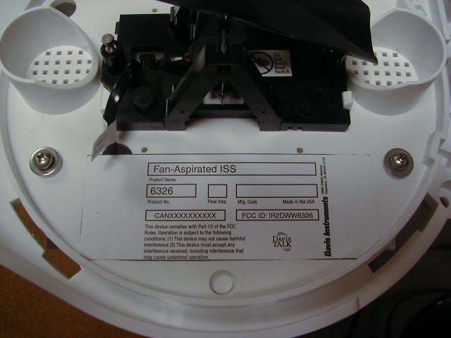
Fan-Aspirated ISS Transmitter Size: 4.75” W x 1.75” H Material: vinyl Location: On the rain collector plate, protected from weather. The user will see the label when they install the ISS and during routine maintanence of the rain collector This device complies with Part 15 of the FCC Rules. Operation is subject to the following conditions: (1) This device may not cause harmful interference (2) This device must accept any interference received, including interference that may cause undesired operation. 3465 Diablo Avenue Hayward, CA 94545-2778 Mfg. Code Product Name Product No. Made in the USA Final Insp. Fan-Aspirated ISS 6326 FCC ID: IR2DWW6326 CANXXXXXXXXXX
Test Report
Page 1 of 28 Report No: FC01-048A DAVIS INSTRUMENTS ADDENDUM TO FC01-048 FOR THE ISS PLUS WITH SOLAR-POWERED FAN ASPIRATED RADIATION SHIELD, 6326 FCC PART 15 SUBPART C SECTION 15.249 & 15.209 COMPLIANCE DATE OF ISSUE: JULY 11, 2001 PREPARED FOR: Davis Instruments 3465 Diablo Ave. Hayward, CA 94545 PREPARED BY: Joyce Walker CKC Laboratories, Inc. 5473A Clouds Rest Mariposa, CA 95338 W.O. No.: 76968Date of test: June 28 and July 11, 2001 Report No.: FC01-048A This report contains a total of 28 pages and may be reproduced in full only. Partial reproduction may only be done with the written consent of CKC Laboratories, Inc. Page 2 of 28 Report No: FC01-048A TABLE OF CONTENTS Administrative Information ............................................................................................. 3 Summary of Results......................................................................................................... 4 Test Overview..................................................................................................................4 Modifications Required for Compliance ......................................................................... 4 Approvals......................................................................................................................... 4 Equipment Under Test (EUT) Description...................................................................... 5 Equipment Under Test..................................................................................................... 5 Peripheral Devices ........................................................................................................... 5 15.33 Frequency Range Tested ....................................................................................... 5 EUT Operating Frequency............................................................................................... 5 Bandwidth........................................................................................................................ 5 Temperature and Humidity During Testing .................................................................... 5 Report of Measurements.................................................................................................. 6 Table 1: 15.249(a) Fundamental Radiated Emission Levels ..........................................6 Table 2: 15.249(c)/15.209 Six Highest Radiated Emission Levels: 9kHz - 1000MHz ..7 Table 3: 15.249(c)/15.209 Six Highest Radiated Emission Levels: 1-10GHZ...............8 Measurement Uncertainty................................................................................................ 9 EUT Setup .......................................................................................................................9 Correction Factors ........................................................................................................... 10 Table A: Sample Calculations ............................................................................. 10 Test Instrumentation and Analyzer Settings.................................................................... 11 Table B: 15.35 Analyzer Bandwidth Settings Per Frequency Range.................. 11 Spectrum Analyzer Detector Functions............................................................... 12 Peak ......................................................................................................... 12 Quasi-Peak............................................................................................... 12 Average.................................................................................................... 12 EUT Testing ....................................................................................................................13 Radiated Emissions ............................................................................................. 13 Transmitter Characteristics.............................................................................................. 14 15.203 Antenna Requirements ............................................................................ 14 15.205 Restricted Bands ...................................................................................... 14 15.249(a) Power Output - Part 15 Subpart C....................................................... 14 Appendix A : Information About The Equipment Under Test........................................ 15 I/O Ports............................................................................................................... 16 Crystal Oscillators ............................................................................................... 16 Printed Circuit Boards ......................................................................................... 16 Cable Information................................................................................................ 17 Photograph Showing Radiated Emissions ........................................................... 19 Photograph Showing Radiated Emissions ........................................................... 20 Appendix B: Test Equipment List ................................................................................... 21 Appendix C: Measurement Data Sheets .......................................................................... 22 Page 3 of 28 Report No: FC01-048A CKC Laboratories, Inc. has received Certificates of Accreditation from the following agencies: A2LA (USA); DATech (Germany); BSMI (Taiwan); Nemko (Norway); and GOST (Russia). CKC Laboratories, Inc has received test site Registration Acceptance from the following agencies: FCC (USA); VCCI (Japan); and Industry Canada. CKC Laboratories, Inc. has received Letters of Acceptance through an MRA for the following agencies: ACA/NATA (Australia); SABS (South Africa); SWEDAC (Sweden); Radio Communications Agency (RA); HOKLAS (Hong Kong); Bakom (Swiss); BIPT (Belgium); Denmark Telestyrelsen;…
Text truncated - open the document above for the full version.
Test Setup Photos
Radiated Emissions - Back View
Contact Information
Applicant
Bruce Walter(Sr Design Engineer)
Technical Contact
CKC Laboratories, Inc.Joyce Walker
[email protected]1-800-500-4362
5473A Clouds Rest · Mariposa, California · United States
Non-Technical Contact
CKC Laboratories, Inc.Joyce Walker
[email protected]1-800-500-4362
Test Firm
CKC Laboratories, Inc.Steve Behm
Technical Specifications
| # | Rule Parts | Frequency Range | Power Output |
|---|---|---|---|
| 1 | 15C | 916.5 MHz - 916.5 MHz | - |
Other Applications from Davis Instruments
IR2DWW6313U
Jan 03, 2023WeatherLink Console
Equipment Class
DTS - Digital Transmission System
IR2DWW765Y
Jun 09, 2005Vantage Pro 2 Wireless Repeater
Equipment Class
DSS - Part 15 Spread Spectrum Transmitter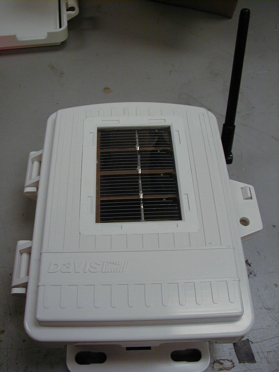
IR2DWW6345
Mar 13, 2005Measurement Station
Equipment Class
DSS - Part 15 Spread Spectrum Transmitter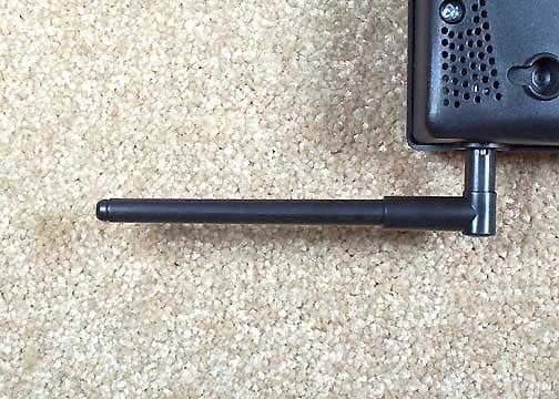
IR2DWW6312
Sep 29, 2004Integrated Vantage Pro 2 Console.
Equipment Class
DSS - Part 15 Spread Spectrum Transmitter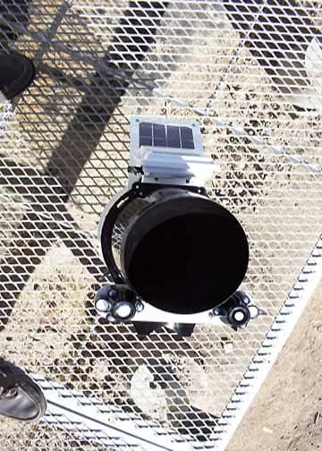
IR2DWW6328
Sep 29, 2004Integrated Sensor Suite 2 with SPARS
Equipment Class
DSS - Part 15 Spread Spectrum Transmitter