IR2DWW7614Weather Transmitter
Davis Instruments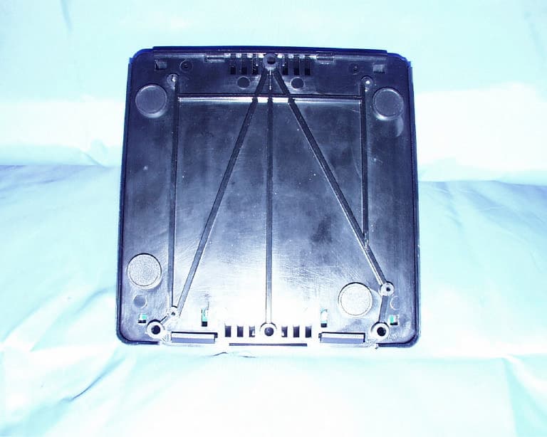
Click to zoom
Application Details
- Equipment Class
- DXT - Part 15 Low Power Transceiver, Rx Verified
- Date of Grant
- Sep 14, 1999
- Application Purpose
- Original Equipment
- Date of Application
- May 05, 1999
- Equipment Note
- Weather Transmitter
- Frequency Range
- 916.50000000 - 916.50000000
- Company
- Davis Instruments
- Country
- United States
Documents & Files
Document Text
Text extracted from the exhibit documents filed with the FCC. Open a document above to read the original.
Users Manual
Product # 7614 & 7615 Wireless R epeater Installation Manual The Wireless Repeater receives data from a Wireless Weather Station sensor array and re-transmits it to the console. The repeater serves to extend the transmission range and improve reception between the sensor array’s trans- mitter and the console’s receiver. One repeater can send data to any number of Monitor II or Wizard III consoles, as long as each console contains a receiver. It can also receive and re-transmit data from up to 8 sensor arrays, as long as each array has a transmitter set to a unique ID code. The repeater’s flexibility allows you to put together your weather system in a number of different ways. The most common setup is to plant the repeater in between a transmitter and a receiver to improve reception. Another possibility is to plant a series of repeaters to carry the transmitter’s signal over a longer distance, or around obstacles. Note: The Wireless Repeater operates on a low power frequency that does not require you to obtain an FCC license. Installing the Wireless Repeater How you go about installing the repeater depends on how many repeaters and transmitters you plan to install. The first section below will discuss the most common and simplest installation—that of one transmitter, one repeater and one receiver. The following section will discuss daisy-chaining the repeaters in succession to increase the range. Single Transmitter, Single Repeater Installation If you have just one sensor array (with transmitter) and just one repeater, sim- ply follow the instructions below to install your system. Page 2Wireless Repeater Choosing a Location F AC-Powered Repeaters Install in a sheltered location, with access to an AC-power outlet. Posi- tion between the transmitter and the receiver so as to minimize the num- ber of walls and other obstacles between both the transmitter and the repeater or the repeater and the receiver. F Solar-Powered Repeaters Find an outdoor location between the transmitter and the receiver so as to minimize range and obstructions. Position the solar panel such that it will receive maximum exposure. Setting up the Repeater The repeater is pre-set by the factory to listen for a transmitter whose ID code is also set to the factory default. If you have not reset the transmitter’s ID code from the factory default, then your repeater should pick up its signal automati- cally. If you have changed the transmitter ID code to one of the 7 other optional dip switch settings, you need to set the repeater to listen for that ID code. To do so, first find your current transmitter setting in the following table: Then, set your repeater to listen for that ID code by flipping the appropriate SENSORLINK TX dip switch. For example, if your transmitter’s dip switches are set to OFF, ON, OFF, then you would flip dip switch #3 on your repeater to ON. Powering the Repeater To apply power to the repeater, do the following: F AC-Powered Repeaters Plug the AC-power adapter into the jack marked POWER, and into an AC-power outlet. F Solar-Powered Repeaters Plug the solar power cord into the the jack marked POWER. ID C ODE D IP S WITCH 1D IP S WITCH 2D IP S WITCH 3 #1 (default) offoffoff #2 offoffON #3 offONoff #4 offONON #5 ONoffoff #6 ONoffON #7 ONONoff #8 ONONON Multiple Repeaters InstallationPage 3 Both LEDs should flash once when power is applied. If all is well, both LEDs should flash again, two times quickly, about 12 seconds later. After that second double-flash, the unit begins looking for a signal. If it finds one, the lower LED will flash as the data is received and then the upper one will flash as it trans- mits. Test Mode In test mode the lower green LED flashed each time the unit receives data. The upper green LED flashes when it re-transmits that data. Use this mode to ver- ify that your transmitter is working. Turn off test mode to get the longest bat- tery life. Test mode is enabled by toggling the fourth Repeater ID dip switch to the ON position and then, if necessary, removing and reapplying power. Multiple Repeaters Installation If you have more than one repeater in your network, follow the instructions as if for a single repeater installation but, before you apply power, set the repeater ID codes so that each will listen to the repeater before it in succession. The first repeater (i.e., the repeater closest to the transmitter) needs no adjustment. The second repeater, however, needs to be set to Repeater ID #2; and the third, to #3; and so on. In this way, the third repeater will only tune into signals from the second, and the second will only tune into signals from the first, and so on, thereby improving reception. To set each repeater’s ID code (except the first), use the table below to set the Repeater ID dip switches: Once you have set the ID codes, simply continue with the “Powering the Repeater” instructions on page 2. There is no need to configure the repeaters to listen to a specific transmitter ID code, unless you want a repeater to listen to an entirely new transmitter aside from the one whose signal it’s repeating. ID C ODE D IP S WITCH 1D IP S WITCH 2D IP S WITCH 3 #1 (default) offoffoff #2 offoffON #3 offONoff #4 offONON #5 ONoffoff #6 ONoffON #7 ONONoff #8 ONONON Product Numbers: 7614 & 7615 Davis Instruments Part Number: 7395-105 Wireless Repeater Installation Manual Rev. A Manual (4/29/99) Controlled Online: Weather Manuals:Accessories:Wireless Repeater This product complies with the essential protection requirements of the EC EMC Directive 89/336/EC. © 1998 Davis Instruments Corp. All rights reserved. 3465 Diablo Avenue, Hayward, CA 94545-2778 510-732-9229 • Fax: 510-732-9188 E-mail: [email protected] • www.davisnet.com Specifications SensorLink Repeater Transmit frequency: 916.5 MHz ID codes: 8 user-selectable License: Low power (less than 1 mW), no license required Temperature range: -40 to 60 °C Power Input: 5 to 12 VDC output @ 1mA FCC Part 15 Class B Registration Warning Th…
Text truncated - open the document above for the full version.
Cover Letter(s)
Agent Authorization ______________________________________________________________________________________________ Date:6/26/01 Federal Communications Commission Authorization and Evaluation Division Equipment Authorization Branch 7435 Oakland Mills Road Columbia, MD 21046 To whom it may concern: We, the undersigned, hereby authorize Compliance Engineering Services, Inc. to act on our behalf in all manners relating to application for equipment authorization, including signing of all documents relating to these matters. Any and all acts carried out by Compliance Engineering Service, Inc. on our behalf shall have the same effect as acts of our own. We, the undersigned, hereby certify that we are not subject to a denial of federal benefits, that includes FCC benefits, pursuant to Section 5301 of the Anti-Drug Abuse Act of 1988, 21 U.S.C. 853(a). This authorization is valid until further written notice from the applicant. Sincerely Yours, Jeff Thayer Engineering Manager Davis Instruments, Inc. ... 1 3465 Diablo Ave. Hayward, CA 94545(510) 732-9229 WWW.Davisnet.com
Cover Letter(s)
FCC Application Confidentiality ______________________________________________________________________________________________ Federal Communications Commission Authorization and Evaluation Division 7435 Oakland Mills Road Columbia, MD 21046 Re: Request for Confidentiality In reference to the application under FCC ID: IR2DWW7614, and pursuant to Sections 0.457(d)(1)(ii) and 0.459 of the Commission's Rules, the Applicant hereby requests confidential treatment of the accompanying information as outlined below: Document titled "Repeater Theory", total 1 page. Document titled "Repeater Manual", total 4 pages. Document titled "Repeater Schematic", total 2 pages. The above materials contain trade secrets and proprietary information not customarily released to the public. The public disclosure of these matters might be harmful to the Applicant and provide unjustified benefits to its competitors. The Applicant understands that pursuant to Rule 0.457(d)(1)(ii), disclosure of this Application and all accompanying documentation will not be made before the date of the Grant for this application. Sincerely, Jeff Thayer Engineering Manager 510-732-9229 510-732-9188 (fax) [email protected] 1 3465 Diablo Ave. Hayward, CA 94545(510) 732-9229 WWW.Davisnet.com
ID Label/Location Info
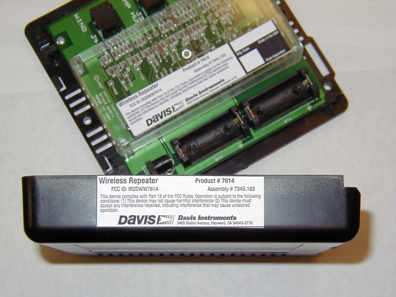
4/30/99 Wireless Repeater Model # 7614 Theor y of Operation The Wireless Repeater consists of a single printed circuit board (PCB). Its purpose is to receive data packets from a SensorLink Transmitter, and rebroadcast them with some ad- ditional information appended to the end. The data packet is on-off keyed standard 4800 baud NRZ patterns from a UART, six bytes (about 12.5mS) from a SensorLink Transmitter, and re-sent as nine bytes (about 18mS), and packets are occur about every 2.5 seconds. The packets are received by an RFM RX2010 module, sent to a microprocessor for buffer- ing and checking, then forwarded to an RFM HX2000 transmitter module for broadcast. These RFM modules operate at 916.5MHz, and use on-circuit-board traces for antennas. See attached schematic diagram #07312.050. FCC ID Label format and location The label will be mounted on the front of the product. 3465 Diablo Ave., Hayward, CA 94545, U.S.A. (510) 732-9229 * FAX: (510) 732-9188 Wireless Repeater FCC ID: IR2DWW7614 Product # 7614 Assembly # 7345.183 This device complies with Part 15 of the FCC Rules. Operation is subject to the following conditions: (1) this device may not cause harmful interference, and (2) this device must accept any interference received, including interference that may cause undesired operation. 3465 Diablo Avenue, Hayward, CA 94545-2778 Mfg. CodeMade in the USA Final Inspection
ID Label/Location Info
Wireless Repeater FCC ID: IR2DWW7614 Product # 7614 Assembly # 7345.183 This device complies with Part 15 of the FCC Rules. Operation is subject to the following conditions: (1) This device may not cause harmful interference (2) This device must accept any interference received, including interference that may cause undesired operation. 3465 Diablo Avenue, Hayward, CA 94545-2778 Mfg. CodeMade in the USA Final Inspection Size: 4"W x 0.875"H Material: Vinyl Location: One label on the interior, clear cover, another on the side of the exterior, black cover.
Test Report
ELECTROMAGNETIC EMISSIONS COMPLIANCE REPORT INTENTIONAL RADIATOR CERTIFICATION TO FCC PART 15 SUBPART C REQUIREMENT TEST REPORT FOR 916MHz SENSORLINK TRANCEIVER REPEATER FCC ID: IR2DWW7614 MODEL NO: 7614 REPORT NO: 99U0131 APRIL 12,1999 Prepared for DAVIS INSTRUMENTS 3465 Diablo Ave. Hayward, CA 94545 Prepared by COMPLIANCE CERTIFICATION SERVICES, INC. 1366 BORDEAUX DRIVE SUNNYVALE, CA 94089, U.S.A. TEL: (408) 752-8166 FAX: (408) 752-8168 TABLE OF CONTENTS PAGE NO 1.VERIFICATION OF COMPLIANCE............................................................................................................1 2.DESCRIPTION OF EQUIPMENT UNDER TEST (EUT).......................................................................2 3.TEST LOCATION...............................................................................................................................................2 4.EQUIPMENT MODIFICATIONS..................................................................................................................2 5.TEST RESULT SUMMARY.............................................................................................................................3 RADIATED EMISSIONS...........................................................................................................................................3 TEST REQUIREMENT: 15.249(A)(B).......................................................................................................................3 OUT-OF-BAND EMISSIONS....................................................................................................................................9 TEST REQUIREMENT: 15.249(C)............................................................................................................................9 AC LINE CONDUCTED EMISSIONS.................................................................................................................11 TEST REQUIREMENT: 15.207................................................................................................................................11 EUT SETUP PHOTO.................................................................................................................................................13 PROJECT NO: 99U0131 DATE: APRIL 12, 1999 FCC ID: IR2DWW7614 EUT: 916 MHz SENSORLINK TRANCIEVER REPEATER PAGE NO: 1 COMPLIANCE CERTIFICATION SERVICES, INC.DOCUMENT NO:CCSUP4031B 1366 BORDEAUX DRIVE, SUNNYVALE, CA 94089TEL:(408)752-8166 FAX:(408)752-8168 This report shall not be reproduced except in full, without the written approval of CCS. 1.VERIFICATION OF COMPLIANCE COMPANY NAME:DAVIS INSTRUMENTS 3465 DIABLO AVE. HAYWARD, CA 94545 CONTACT PERSON:JEFF THAYER / ENGINEERING MANAGER TELEPHONE NO:(510) 732-9229 EUT DESCRIPTION:916 MHz SENSORLINK TRANSCIEVER REPEATER MODEL NAME:7614 DATE TESTED :APRIL 12, 1999 LIMITS APPLY TO: FCC PART 15 SECTION 15.249 TECHNICAL LIMITSTEST RESULT Radiated Emission of fundamental FrequencyPASSED Radiated Emission of Harmonic FrequencyPASSED Radiated Emission Outside the BandPASSED The above equipment was tested by Compliance Certification Services Inc. for compliance with the requirements set forth in CFR 47 PART 15 SUBPART C. This said equipment in the configuration described in this report shows the maximum emission levels emanating from equipment are within the compliance requirements. MIKE C.I. KUO / VICE PRESIDENT COMPLIANCE CERTIFICATION SERVICES, INC. PROJECT NO: 99U0131 DATE: APRIL 12, 1999 FCC ID: IR2DWW7614 EUT: 916 MHz SENSORLINK TRANCIEVER REPEATER PAGE NO: 2 COMPLIANCE CERTIFICATION SERVICES, INC.DOCUMENT NO:CCSUP4031B 1366 BORDEAUX DRIVE, SUNNYVALE, CA 94089TEL:(408)752-8166 FAX:(408)752-8168 This report shall not be reproduced except in full, without the written approval of CCS. 2.DESCRIPTION OF EQUIPMENT UNDER TEST (EUT) CHASSIS TYPEPLASTIC Frequency Range916.5 MHz Transmitter chipRFM; HX2000 Receiver chipRFM; RX2010 Antenna RequirementPermanently Attached ( Internal) Power supply Manuf/ modelDavis Instrument; 7916 Power requirement9Vdc Emission DesignatorF1D 3.TEST LOCATION All emissions tests were performed at: Compliance Consulting Services 561F Monterey Road Morgan Hill, CA 95087 CCS has site descriptions on file with the FCC for 10 and 3 meter site configurations. CCS is a NVLAP accredited facility. 4.EQUIPMENT MODIFICATIONS To achieve compliance Levels, the following change(s) were made during compliance testing: Mod.#1A 47 ohm resistor was place in series with antenna transmitter to reduce power output. PROJECT NO: 99U0131 DATE: APRIL 12, 1999 FCC ID: IR2DWW7614 EUT: 916 MHz SENSORLINK TRANCIEVER REPEATER PAGE NO: 3 COMPLIANCE CERTIFICATION SERVICES, INC.DOCUMENT NO:CCSUP4031B 1366 BORDEAUX DRIVE, SUNNYVALE, CA 94089TEL:(408)752-8166 FAX:(408)752-8168 This report shall not be reproduced except in full, without the written approval of CCS. 5.TEST RESULT SUMMARY Radiated Emissions Test Requirement: 15.249(A)(B) Measurement Equipment Used: HP Spectrum Analyzer/8566B (Cal Due: 09/99) HP Spectrum Display/85662A (Cal Due: 09/99) HP Quasi-Peak Detector/85650A (Cal Due: 09/99) HP Pre-Amp(P5)/8447D (Cal Due: 09/99) Emco Log-Periodic Antenna/3146 (Cal Due: 09/99) TEST SETUP FOR MEASUREMENT OF FUNDAMENTAL FREQUENCY Antenna mast Ground plane 1 - 4 meters 3 meters turntable preamplifier/spectrum analyzer Fig.1(a) Test Procedures 1) Place the EUT on the turntable as shown. The EUT was placed as close as possible to the center of the turntable with the axis of rotation going through the EUT antenna when in vertical or horizontal polarization. Activated Eut to transmit. PROJECT NO: 99U0131 DATE: APRIL 12, 1999 FCC ID: IR2DWW7614 EUT: 916 MHz SENSORLINK TRANCIEVER REPEATER PAGE NO: 4 COMPLIANCE CERTIFICATION SERVICES, INC.DOCUMENT NO:CCSUP4031B 1366 BORDEAUX DRIVE, SUNNYVALE, CA 94089TEL:(408)752-8166 FAX:(408)752-8168 This report shall not be reproduced except in full, without the written approval of CCS. 2) The log periodic search antenna was …
Text truncated - open the document above for the full version.
Contact Information
Applicant
Bruce Walter(Sr Design Engineer)
Technical Contact
COMPLIANCE ENGINEERING SERVICES, INC.MIKE KUO
[email protected]408-752-8166
1366 BORDEAUX DRIVE · SUNNYVALE, California · United States
Non-Technical Contact
COMPLIANCE ENGINEERING SERVICES, INC.MIKE KUO
[email protected]408-752-8166
Test Firm
Compliance Certification Services IncSteve Cheng
Technical Specifications
| # | Rule Parts | Frequency Range | Power Output |
|---|---|---|---|
| 1 | 15C | 916.5 MHz - 916.5 MHz | - |
Other Applications from Davis Instruments
IR2DWW6313U
Jan 03, 2023WeatherLink Console
Equipment Class
DTS - Digital Transmission System
IR2DWW765Y
Jun 09, 2005Vantage Pro 2 Wireless Repeater
Equipment Class
DSS - Part 15 Spread Spectrum Transmitter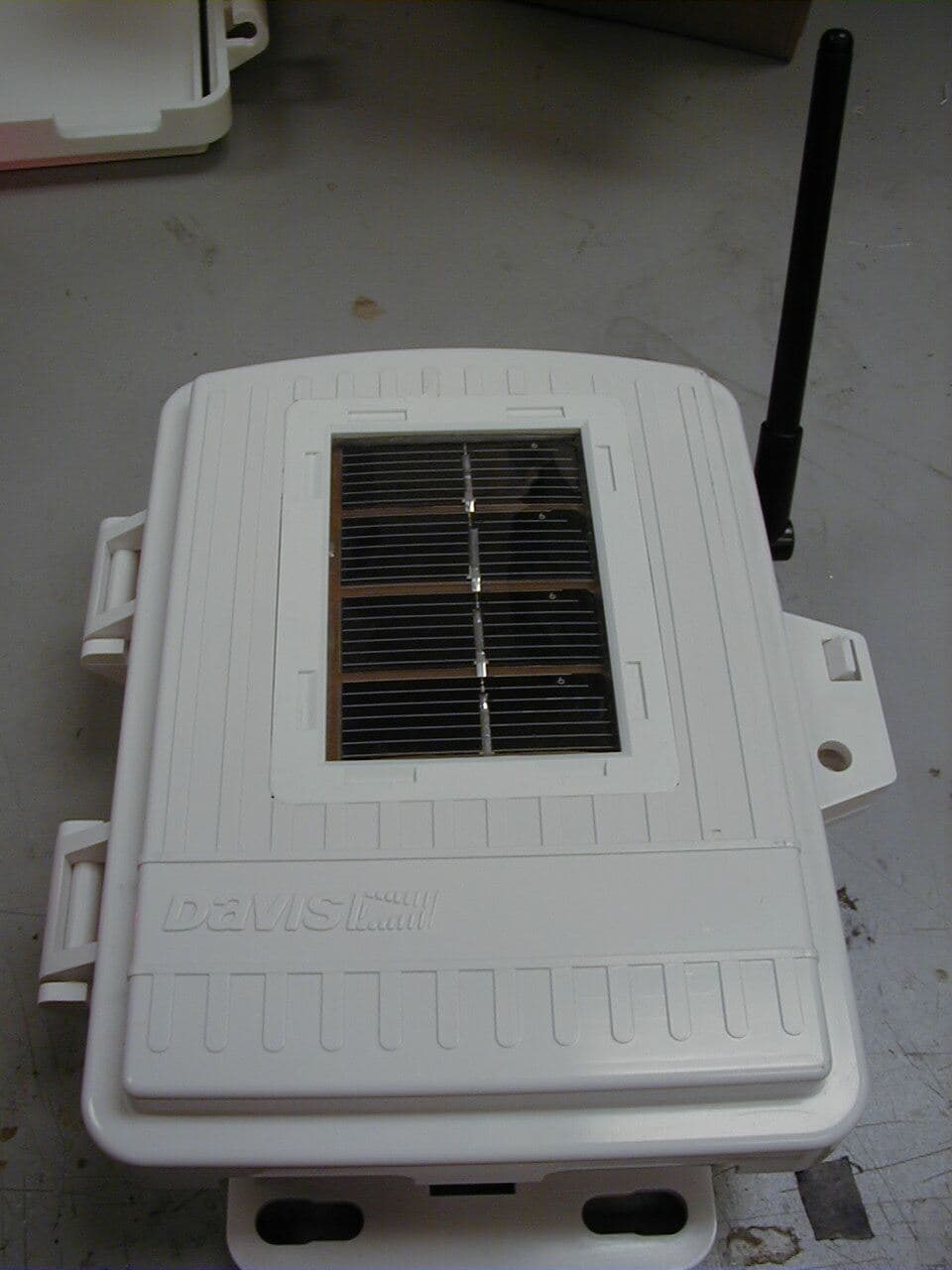
IR2DWW6345
Mar 13, 2005Measurement Station
Equipment Class
DSS - Part 15 Spread Spectrum Transmitter
IR2DWW6312
Sep 29, 2004Integrated Vantage Pro 2 Console.
Equipment Class
DSS - Part 15 Spread Spectrum Transmitter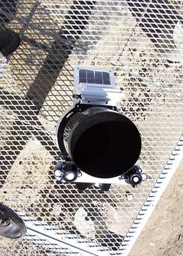
IR2DWW6328
Sep 29, 2004Integrated Sensor Suite 2 with SPARS
Equipment Class
DSS - Part 15 Spread Spectrum Transmitter