IR2DWW7617ConsoleLink, Model 7617
Davis Instruments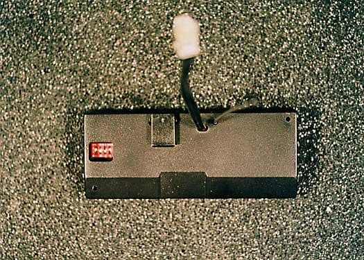
Click to zoom
Application Details
- Equipment Class
- DXX - Part 15 Low Power Communication Device Transmitter
- Date of Grant
- Nov 17, 1999
- Application Purpose
- Original Equipment
- Date of Application
- Aug 24, 1999
- Equipment Note
- ConsoleLink, Model 7617
- Frequency Range
- 916.50000000 - 916.50000000
- Company
- Davis Instruments
- Country
- United States
Documents & Files
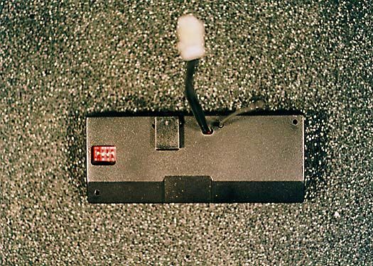
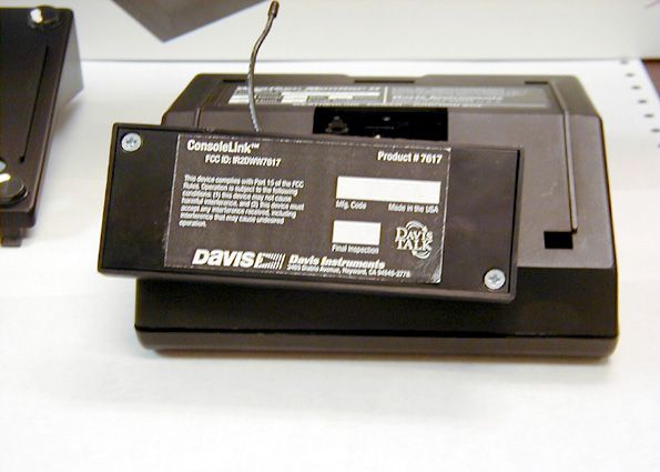
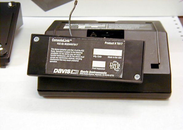
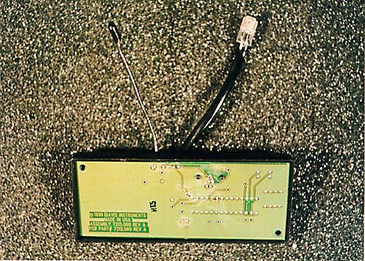
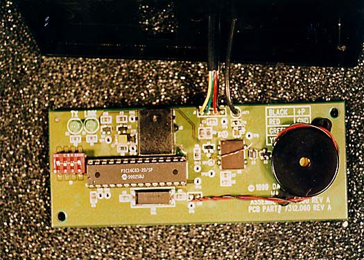
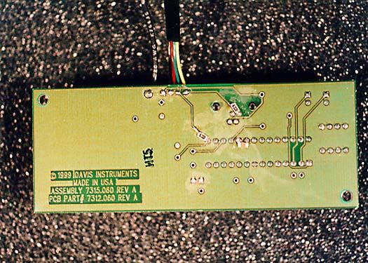
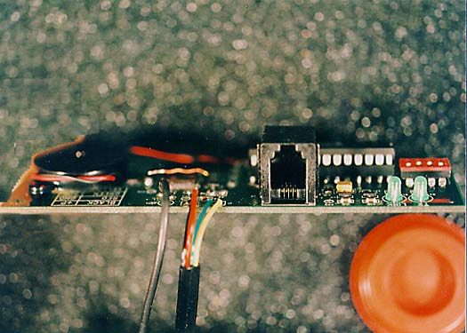
Document Text
Text extracted from the exhibit documents filed with the FCC. Open a document above to read the original.
Users Manual
Product # 7617 C ONSOLE L INK I NSTALLATION M ANUAL The ConsoleLink Transmitter (Tx) connects to a host Weather Monitor II, Weather Wizard II & III, or Perception II. The ConsoleLink Tx transmits weather data from your host station to other DavisTalk™ compatible consoles and receiving units. This allows you to send weather data to one or more loca- tions without using any wires. Providing you have the necessary sensors, the ConsoleLink Tx will send the following weather data: The ConsoleLink Tx is user-configurable to communicate on one of 8 different ID codes. This allows multiple systems to coexist in the same geographical area. The unit includes a pass-thru connector so that a WeatherLink data logger can still be used with the host station. Note: The ConsoleLink Tx operates on a low power frequency that does not require you to obtain an FCC license. Weather Monitor II Weather Wizard II and III Perception Inside TemperatureYesYesYes Inside HumidityYesNoYes Outside TemperatureYesYesNo Outside HumidityYesNoNo RainfallYesYesNo Wind SpeedYesYesNo Wind DirectionYesYesNo BarometerYesNoYes Page 2ConsoleLink I NSTALLING C ONSOLE L INK T RANSMITTER The ConsoleLink Tx consists of a single module. (Refer to drawing 1A) Attaching the ConsoleLink Tx to the Host Station The transmitter has a short cable with modular connector on its free end. Insert this plug into your weather station in the jack marked "WeatherLink". The unit sits in the console base as shown. Range The range of radio transmission depends on several factors. Try to position the DavisTalk compatible receiver(s) as close to the ConsoleLink Tx as possible. Typical maximum ranges: F Line of sight: 800 feet (240 m) F Through walls and ceilings: 100 to 400 feet (30 to 120 m) F Through trees and foliage: 100 to 400 feet (30 to 120 m) Setting the ID Code The ConsoleLink Tx may be set to use any of eight selectable ID codes (the default is ID Code #1). The transmitter and receiver will only communicate with each other if they are both set to the same ID code. Use the default setting unless you have another Davis wireless system operating nearby which you want to work separately from the new system. The dip switch settings for the eight possible codes are shown below. To change to another ID, toggle dip switches 1, 2, and/or 3 on the transmitter to the desired code. Remember that the transmitter and receiver must use the same ID code in order to communicate so if you change the ID code on the transmitter, you must change the ID Code on the receiver to match. Note: Dip switch #4 is used for testing and warnings, not for ID codes (see “Test Mode” on page 3). ID C ODE D IP S WITCH 1D IP S WITCH 2D IP S WITCH 3 #1 (default) offoffoff #2offoffON #3offONoff #4offONON #5ONoffoff #6ONoffON #7ONONoff #8ONONON TroubleshootingPage 3 Powering Up the ConsoleLink Tx To power up the ConsoleLink Tx, apply power to your host weather station. If the ConsoleLink Tx is working properly, it will make a single or double beep about 30 seconds after the weather station is energized. The single beep indi- cates that the unit is working properly and that no WeatheLink data logger is connected to the unit. Two beeps indicate that the unit is working properly and that a WeatheLink data logger is connected to the unit. Test Mode To verify that the ConsoleLink Tx transmitting data, a test mode is provided. In this mode the beeper beeps each time the unit transmits data (2.5 second interval). Using a WeatherLink Data Logger Install the ConsoleLink Tx as instructed above. Plug the short (3", 75mm) mod- ular connector from the WeatherLink into the ConsoleLink Tx as shown in drawing 4. Alternately, use the optional 8 ft. extension cable and coupler to make the connection. T ROUBLESHOOTING While the ConsoleLink Transmitter is designed to provide years of trouble-free operation, occasional problems may arise. If you experience a problem, please check the troubleshooters listed below before calling the factory. If you still are unable to solve the problem, call the factory at (510) 732-7814 for assistance. Please do not return your unit for repair without prior authorization. F Console is receiving erratic data Enable the Test Mode on the transmitter. If two beeps or more are heard in a 2.5-second interval, then another Davis wireless system may be operating nearby on the same ID, or a cordless phone may be operating within 10 feet of the receiver. Either try changing to a different ID code on both the receiver and the transmitter, or try moving the phone. Reapply power to the console to activate the new ID code. F Console is not receiving any data The transmitter and the receiver may be too far apart, or something in their path may be interfering, such as foliage, furnishings or cordless phones. Enable Test Mode on the transmitter to see if it is receiving data. Try mov- ing the receiver closer to the transmitter or vice versa; or eliminating possi- ble path interferences. Product Number: 7617 Davis Instruments Part Number: 7395-067 ConsoleLink Installation Manual Rev. A Manual (8/5/99) Controlled Online: Weather Manuals:DavisTalk:ConsoleLink © 1999 Davis Instruments Corp. All rights reserved. 3465 Diablo Avenue, Hayward, CA 94545-2778 510-732-9229 • Fax: 510-732-9118 E-mail: [email protected] • www.davisnet.com S PECIFICATIONS F Transmit frequency - 916.5 MHz F ID codes - 8 user selectable F License - Low power no license required F Temperature range - 0 to 60 °C FCC P ART 15 C LASS B R EGISTRATION W ARNING This equipment has been tested and found to comply with the limits for a class B digital device, pursuant to Part 15 of the FCC Rules. These limits are designed to provide reasonable protection against harmful interference in a residential installation. This equipment generates, uses and can radiate radio frequency energy and, if not installed and used in accordance with the instruc- tions, may cause harmful interference to radio communications. However, there is no guaran…
Text truncated - open the document above for the full version.
Attestation Statements
Page 1 of 1 Test Location:CKC Laboratories, Inc. • 1653 Los Viboras Rd., Site A • Hollister, Ca 95023 • (831) 637-0485 Customer: Davis Instruments Specification: 15.231(e) Work Order #: 72312 Date: Fri Aug-06-1999 Test Type: Maximized Emissions Time: 14:38:48 Equipment: Weather Data Telemetry Sequence#: 6 Manufacturer:Davis InstrumentsTested By: Wes Norris Model:7617 S/N:Prototype Equipment Under Test (* = EUT): FunctionManufacturerModel #S/N Weather Data Telemetry*Davis Instruments7617Prototype Support Devices: FunctionManufacturerModel #S/N Weather ConsoleDavis Instruments7425WC80921B67 PC LinkDavis Instruments7862LC90802A32 Test Conditions / Notes: Testing to FCC part 15.231 The EUT is fully operational, with Wind Vane and Rain Collector connected. The EUT is transmitting continuously, at full power, in CW Mode. The EUT is receiving its power from the AC Adaptor, which is powered from a 115V/60Hz source. Measurement Data: Reading listed by order taken.Test Distance: 3 Meters AMPLOGCABLE 15.35 #FreqRdngDistCorrSpecMarginPolar MHzdBμVdBdBdBdBTable dBμV/m dBμV/mdBAnt 1 916.513M 79.1 -27.1 +22.5 +4.8 +0.0 +0.0 79.3 74.0 +5.3Vert See item #3 for average reading. 2 916.510M 71.3 -27.1 +22.5 +4.8 +0.0 +0.0 71.5 74.0 -2.5Horiz See item #4 for average reading. 3 916.522M 79.1 -27.1 +22.5 +4.8 -20.0 +0.0 59.3 74.0 -14.7Vert Ave 4 916.523M 71.3 -27.1 +22.5 +4.8 -20.0 +0.0 51.5 74.0 -22.5Horiz Ave
Attestation Statements
Page 1 of 3 Report No: FB97-079 Test Location:CKC Laboratories, Inc. • 1653 Los Viboras Rd., Site A • Hollister, Ca 95023 • (831) 637-0485 Customer: Davis Instruments Specification: FCC 15.249(a) Work Order #: 72312 Date: Fri Aug-06-1999 Test Type: Maximized Emissions Time: 14:38:48 Equipment: Weather Data Telemetry Sequence#: 6 Manufacturer:Davis InstrumentsTested By: Wes Norris Model:7617 S/N:Prototype Equipment Under Test (* = EUT): FunctionManufacturerModel #S/N Weather Data Telemetry*Davis Instruments7617Prototype Support Devices: FunctionManufacturerModel #S/N Weather ConsoleDavis Instruments7425WC80921B67 PC LinkDavis Instruments7862LC90802A32 Test Conditions / Notes: The EUT is fully operational, with Wind Vane and Rain Collector connected. The EUT is transmitting continuously, at full power, in CW Mode. The EUT is receiving its power from the AC Adaptor, which is powered from a 115V/60Hz source. The on time of the transmitter in a 100ms period was measured. This on time divided by the 100ms period is the duty cycle. A 20Log(duty cycle) calculation is then performed and this factor (not to exceed 20dB) is then taken into consideration. This method is specified in CFR 47 Section 15.35(c). Measurement Data: Reading listed by order taken.Test Distance: 3 Meters AMPLOGCABLE 15.35 #FreqRdngDistCorrSpecMarginPolar MHzdBμVdBdBdBdBTable dBμV/m dBμV/mdBAnt 1 916.513M 79.1 -27.1 +22.5 +4.8 +0.0 +0.0 79.3 93.9 -14.6Vert 2 916.510M 71.3 -27.1 +22.5 +4.8 +0.0 +0.0 71.5 93.9 -22.4Horiz 3 916.522M 79.1 -27.1 +22.5 +4.8 -20.0 +0.0 59.3 93.9 -34.6Vert Ave 4 916.523M 71.3 -27.1 +22.5 +4.8 -20.0 +0.0 51.5 93.9 -42.4Horiz Ave Page 2 of 3 Report No: FB97-079 Test Location:CKC Laboratories, Inc. • 1653 Los Viboras Rd., Site A • Hollister, Ca 95023 • (831) 637-0485 Customer: Davis Instruments Specification: FCC 15.249(C) / 15.209 Work Order #: 72312 Date: Mon Oct-25-1999 Test Type: Maximized Emissions Time: 07:19:04 Equipment: Weather Data Telemetry Sequence#: 2 Manufacturer:Davis InstrumentsTested By: Wes Norris Model:7617 S/N:Prototype Equipment Under Test (* = EUT): FunctionManufacturerModel #S/N Weather Data Telemetry*Davis Instruments7617Prototype Support Devices: FunctionManufacturerModel #S/N Weather ConsoleDavis Instruments7425WC80921B67 PC LinkDavis Instruments7862LC90802A32 AC AdaptorAblex7916N/A Test Conditions / Notes: The EUT is fully operational, receiving weather data from the Weather Console.The EUT is transmitting continuously, at full power, in CW Mode. The EUT is receiving its power from the Weather Console, which is powered from the AC Adaptor, which is powered from a 115V/60Hz source. The on time of the transmitter in a 100ms period was measured. This on time divided by the 100ms period is the duty cycle. A 20Log(duty cycle) calculation is then performed and this factor (not to exceed 20dB) is then taken into consideration. This method is specified in CFR 47 Section 15.35(c). Measurement Data: Reading listed by margin.Test Distance: 3 Meters HornAmp_21-12.1-12. #FreqRdng15.35DistCorrSpecMarginPolar MHzdBμVdBdBdBdBTable dBμV/m dBμV/mdBAnt 1 1833.000M 73.9 +26.5 -38.6 +0.3 +3.9 +0.0 66.0 54.0 +12.0Horiz +0.0 2 1833.000M 66.8 +26.5 -38.6 +0.3 +3.9 +0.0 58.9 54.0 +4.9Vert +0.0 3 5499.000M 51.2 +34.9 -39.9 +0.4 +7.3 +0.0 53.9 54.0 -0.1Vert +0.0 4 5499.000M 50.5 +34.9 -39.9 +0.4 +7.3 +0.0 53.2 54.0 -0.8Horiz +0.0 5 6415.500M 47.7 +35.4 -40.3 +0.6 +7.9 +0.0 51.3 54.0 -2.7Vert +0.0 6 6415.500M 46.0 +35.4 -40.3 +0.6 +7.9 +0.0 49.6 54.0 -4.4Horiz +0.0 7 1833.000M 73.9 +26.5 -38.6 +0.3 +3.9 +0.0 46.0 54.0 -8.0Horiz Ave -20.0 8 3666.000M 62.5 +32.4 -38.9 +0.5 +5.8 +0.0 42.3 54.0 -11.7Horiz -20.0 9 1833.000M 66.8 +26.5 -38.6 +0.3 +3.9 +0.0 38.9 54.0 -15.1Vert Ave -20.0 10 9165.000M 47.8 +38.5 -39.0 +0.6 +9.4 +0.0 37.3 54.0 -16.7Vert -20.0 Page 3 of 3 Report No: FB97-079 11 4582.500M 57.1 +32.3 -39.7 +0.6 +6.6 +0.0 36.9 54.0 -17.1Horiz -20.0 12 9165.100M 46.5 +38.5 -39.0 +0.6 +9.4 +0.0 36.0 54.0 -18.0Horiz -20.0 13 4582.500M 55.9 +32.3 -39.7 +0.6 +6.6 +0.0 35.7 54.0 -18.3Vert -20.0 14 7332.000M 49.0 +36.6 -39.2 +0.3 +8.3 +0.0 35.0 54.0 -19.0Vert -20.0 15 8248.500M 47.2 +37.6 -40.2 +0.8 +9.1 +0.0 34.5 54.0 -19.5Horiz -20.0 16 8248.500M 46.8 +37.6 -40.2 +0.8 +9.1 +0.0 34.1 54.0 -19.9Vert -20.0 17 5499.000M 51.2 +34.9 -39.9 +0.4 +7.3 +0.0 33.9 54.0 -20.1Vert Ave -20.0 18 7332.000M 47.3 +36.6 -39.2 +0.3 +8.3 +0.0 33.3 54.0 -20.7Horiz -20.0 19 5499.000M 50.5 +34.9 -39.9 +0.4 +7.3 +0.0 33.2 54.0 -20.8Horiz Ave -20.0 20 3666.000M 52.3 +32.4 -38.9 +0.5 +5.8 +0.0 32.1 54.0 -21.9Vert -20.0 21 6415.500M 47.7 +35.4 -40.3 +0.6 +7.9 +0.0 31.3 54.0 -22.7Vert Ave -20.0 22 6415.500M 46.0 +35.4 -40.3 +0.6 +7.9 +0.0 29.6 54.0 -24.4Horiz Ave -20.0 23 2749.500M 52.0 +29.7 -37.6 +0.4 +5.0 +0.0 29.5 54.0 -24.5Horiz -20.0 24 2749.500M 49.9 +29.7 -37.6 +0.4 +5.0 +0.0 27.4 54.0 -26.6Vert -20.0
Attestation Statements
Page 1 of 3 Test Location:CKC Laboratories, Inc. • 1653 Los Viboras Rd., Site A • Hollister, Ca 95023 • (831) 637-0485 Customer: Davis Instruments Specification: FCC 15.249(a) Work Order #: 72312 Date: Fri Aug-06-1999 Test Type: Maximized Emissions Time: 14:38:48 Equipment: Weather Data Telemetry Sequence#: 6 Manufacturer:Davis InstrumentsTested By: Wes Norris Model:7617 S/N:Prototype Equipment Under Test (* = EUT): FunctionManufacturerModel #S/N Weather Data Telemetry*Davis Instruments7617Prototype Support Devices: FunctionManufacturerModel #S/N Weather ConsoleDavis Instruments7425WC80921B67 PC LinkDavis Instruments7862LC90802A32 Test Conditions / Notes: The EUT is fully operational, with Wind Vane and Rain Collector connected. The EUT is transmitting continuously, at full power, in CW Mode. The EUT is receiving its power from the AC Adaptor, which is powered from a 115V/60Hz source. The on time of the transmitter in a 100ms period was measured. This on time divided by the 100ms period is the duty cycle. A 20Log(duty cycle) calculation is then performed and this factor (not to exceed 20dB) is then taken into consideration. This method is specified in CFR 47 Section 15.35(c). Measurement Data: Reading listed by order taken.Test Distance: 3 Meters AMPLOGCABLE 15.35 #FreqRdngDistCorrSpecMarginPolar MHzdBμVdBdBdBdBTable dBμV/m dBμV/mdBAnt 1 916.513M 79.1 -27.1 +22.5 +4.8 +0.0 +0.0 79.3 93.9 -14.6Vert 2 916.510M 71.3 -27.1 +22.5 +4.8 +0.0 +0.0 71.5 93.9 -22.4Horiz 3 916.522M 79.1 -27.1 +22.5 +4.8 -20.0 +0.0 59.3 93.9 -34.6Vert Ave 4 916.523M 71.3 -27.1 +22.5 +4.8 -20.0 +0.0 51.5 93.9 -42.4Horiz Ave Page 2 of 3 Test Location:CKC Laboratories, Inc. • 1653 Los Viboras Rd., Site A • Hollister, Ca 95023 • (831) 637-0485 Customer: Davis Instruments Specification: FCC 15.249(C) / 15.209 Work Order #: 72312 Date: Mon Oct-25-1999 Test Type: Maximized Emissions Time: 07:19:04 Equipment: Weather Data Telemetry Sequence#: 2 Manufacturer:Davis InstrumentsTested By: Wes Norris Model:7617 S/N:Prototype Equipment Under Test (* = EUT): FunctionManufacturerModel #S/N Weather Data Telemetry*Davis Instruments7617Prototype Support Devices: FunctionManufacturerModel #S/N Weather ConsoleDavis Instruments7425WC80921B67 PC LinkDavis Instruments7862LC90802A32 AC AdaptorAblex7916N/A Test Conditions / Notes: The EUT is fully operational, receiving weather data from the Weather Console.The EUT is transmitting continuously, at full power, in CW Mode. The EUT is receiving its power from the Weather Console, which is powered from the AC Adaptor, which is powered from a 115V/60Hz source. The on time of the transmitter in a 100ms period was measured. This on time divided by the 100ms period is the duty cycle. A 20Log(duty cycle) calculation is then performed and this factor (not to exceed 20dB) is then taken into consideration. This method is specified in CFR 47 Section 15.35(c). Measurement Data: Reading listed by margin.Test Distance: 3 Meters HornAmp_21-12.1-12. #FreqRdng15.35DistCorrSpecMarginPolar MHzdBμVdBdBdBdBTable dBμV/m dBμV/mdBAnt 1 1833.000M 73.9 +26.5 -38.6 +0.3 +3.9 +0.0 66.0 54.0 +12.0Horiz +0.0 2 1833.000M 66.8 +26.5 -38.6 +0.3 +3.9 +0.0 58.9 54.0 +4.9Vert +0.0 3 5499.000M 51.2 +34.9 -39.9 +0.4 +7.3 +0.0 53.9 54.0 -0.1Vert +0.0 4 5499.000M 50.5 +34.9 -39.9 +0.4 +7.3 +0.0 53.2 54.0 -0.8Horiz +0.0 5 6415.500M 47.7 +35.4 -40.3 +0.6 +7.9 +0.0 51.3 54.0 -2.7Vert +0.0 6 6415.500M 46.0 +35.4 -40.3 +0.6 +7.9 +0.0 49.6 54.0 -4.4Horiz +0.0 7 1833.000M 73.9 +26.5 -38.6 +0.3 +3.9 +0.0 46.0 54.0 -8.0Horiz Ave -20.0 8 3666.000M 62.5 +32.4 -38.9 +0.5 +5.8 +0.0 42.3 54.0 -11.7Horiz -20.0 9 1833.000M 66.8 +26.5 -38.6 +0.3 +3.9 +0.0 38.9 54.0 -15.1Vert Ave -20.0 10 9165.000M 47.8 +38.5 -39.0 +0.6 +9.4 +0.0 37.3 54.0 -16.7Vert -20.0 Page 3 of 3 11 4582.500M 57.1 +32.3 -39.7 +0.6 +6.6 +0.0 36.9 54.0 -17.1Horiz -20.0 12 9165.100M 46.5 +38.5 -39.0 +0.6 +9.4 +0.0 36.0 54.0 -18.0Horiz -20.0 13 4582.500M 55.9 +32.3 -39.7 +0.6 +6.6 +0.0 35.7 54.0 -18.3Vert -20.0 14 7332.000M 49.0 +36.6 -39.2 +0.3 +8.3 +0.0 35.0 54.0 -19.0Vert -20.0 15 8248.500M 47.2 +37.6 -40.2 +0.8 +9.1 +0.0 34.5 54.0 -19.5Horiz -20.0 16 8248.500M 46.8 +37.6 -40.2 +0.8 +9.1 +0.0 34.1 54.0 -19.9Vert -20.0 17 5499.000M 51.2 +34.9 -39.9 +0.4 +7.3 +0.0 33.9 54.0 -20.1Vert Ave -20.0 18 7332.000M 47.3 +36.6 -39.2 +0.3 +8.3 +0.0 33.3 54.0 -20.7Horiz -20.0 19 5499.000M 50.5 +34.9 -39.9 +0.4 +7.3 +0.0 33.2 54.0 -20.8Horiz Ave -20.0 20 3666.000M 52.3 +32.4 -38.9 +0.5 +5.8 +0.0 32.1 54.0 -21.9Vert -20.0 21 6415.500M 47.7 +35.4 -40.3 +0.6 +7.9 +0.0 31.3 54.0 -22.7Vert Ave -20.0 22 6415.500M 46.0 +35.4 -40.3 +0.6 +7.9 +0.0 29.6 54.0 -24.4Horiz Ave -20.0 23 2749.500M 52.0 +29.7 -37.6 +0.4 +5.0 +0.0 29.5 54.0 -24.5Horiz -20.0 24 2749.500M 49.9 +29.7 -37.6 +0.4 +5.0 +0.0 27.4 54.0 -26.6Vert -20.0
Attestation Statements
Page 1 of 3 Test Location:CKC Laboratories, Inc. • 1653 Los Viboras Rd., Site A • Hollister, Ca 95023 • (831) 637-0485 Customer: Davis Instruments Specification: FCC 15.249(a) Work Order #: 72312 Date: Fri Aug-06-1999 Test Type: Maximized Emissions Time: 14:38:48 Equipment: Weather Data Telemetry Sequence#: 6 Manufacturer:Davis InstrumentsTested By: Wes Norris Model:7617 S/N:Prototype Equipment Under Test (* = EUT): FunctionManufacturerModel #S/N Weather Data Telemetry*Davis Instruments7617Prototype Support Devices: FunctionManufacturerModel #S/N Weather ConsoleDavis Instruments7425WC80921B67 PC LinkDavis Instruments7862LC90802A32 Test Conditions / Notes: The EUT is fully operational, with Wind Vane and Rain Collector connected. The EUT is transmitting continuously, at full power, in CW Mode. The EUT is receiving its power from the AC Adaptor, which is powered from a 115V/60Hz source. The on time of the transmitter in a 100ms period was measured. This on time divided by the 100ms period is the duty cycle. A 20Log(duty cycle) calculation is then performed and this factor (not to exceed 20dB) is then taken into consideration. This method is specified in CFR 47 Section 15.35(c). Measurement Data: Reading listed by order taken.Test Distance: 3 Meters AMPLOGCABLE 15.35 #FreqRdngDistCorrSpecMarginPolar MHzdBμVdBdBdBdBTable dBμV/m dBμV/mdBAnt 1 916.513M 79.1 -27.1 +22.5 +4.8 +0.0 +0.0 79.3 93.9 -14.6Vert 2 916.510M 71.3 -27.1 +22.5 +4.8 +0.0 +0.0 71.5 93.9 -22.4Horiz 3 916.522M 79.1 -27.1 +22.5 +4.8 -20.0 +0.0 59.3 93.9 -34.6Vert Ave 4 916.523M 71.3 -27.1 +22.5 +4.8 -20.0 +0.0 51.5 93.9 -42.4Horiz Ave Page 2 of 3 Test Location:CKC Laboratories, Inc. • 1653 Los Viboras Rd., Site A • Hollister, Ca 95023 • (831) 637-0485 Customer: Davis Instruments Specification: FCC 15.249(C) / 15.209 Work Order #: 72312 Date: Mon Oct-25-1999 Test Type: Maximized Emissions Time: 07:19:04 Equipment: Weather Data Telemetry Sequence#: 2 Manufacturer:Davis InstrumentsTested By: Wes Norris Model:7617 S/N:Prototype Equipment Under Test (* = EUT): FunctionManufacturerModel #S/N Weather Data Telemetry*Davis Instruments7617Prototype Support Devices: FunctionManufacturerModel #S/N Weather ConsoleDavis Instruments7425WC80921B67 PC LinkDavis Instruments7862LC90802A32 AC AdaptorAblex7916N/A Test Conditions / Notes: The EUT is fully operational, receiving weather data from the Weather Console.The EUT is transmitting continuously, at full power, in CW Mode. The EUT is receiving its power from the Weather Console, which is powered from the AC Adaptor, which is powered from a 115V/60Hz source. The on time of the transmitter in a 100ms period was measured. This on time divided by the 100ms period is the duty cycle. A 20Log(duty cycle) calculation is then performed and this factor (not to exceed 20dB) is then taken into consideration. This method is specified in CFR 47 Section 15.35(c). Measurement Data: Reading listed by margin.Test Distance: 3 Meters HornAmp_21-12.1-12. #FreqRdng15.35DistCorrSpecMarginPolar MHzdBμVdBdBdBdBTable dBμV/m dBμV/mdBAnt 1 1833.000M 73.9 +26.5 -38.6 +0.3 +3.9 +0.0 66.0 54.0 +12.0Horiz +0.0 2 1833.000M 66.8 +26.5 -38.6 +0.3 +3.9 +0.0 58.9 54.0 +4.9Vert +0.0 3 5499.000M 51.2 +34.9 -39.9 +0.4 +7.3 +0.0 53.9 54.0 -0.1Vert +0.0 4 5499.000M 50.5 +34.9 -39.9 +0.4 +7.3 +0.0 53.2 54.0 -0.8Horiz +0.0 5 6415.500M 47.7 +35.4 -40.3 +0.6 +7.9 +0.0 51.3 54.0 -2.7Vert +0.0 6 6415.500M 46.0 +35.4 -40.3 +0.6 +7.9 +0.0 49.6 54.0 -4.4Horiz +0.0 7 1833.000M 73.9 +26.5 -38.6 +0.3 +3.9 +0.0 46.0 54.0 -8.0Horiz Ave -20.0 8 3666.000M 62.5 +32.4 -38.9 +0.5 +5.8 +0.0 42.3 54.0 -11.7Horiz -20.0 9 1833.000M 66.8 +26.5 -38.6 +0.3 +3.9 +0.0 38.9 54.0 -15.1Vert Ave -20.0 10 9165.000M 47.8 +38.5 -39.0 +0.6 +9.4 +0.0 37.3 54.0 -16.7Vert -20.0 11 4582.500M 57.1 +32.3 -39.7 +0.6 +6.6 +0.0 36.9 54.0 -17.1Horiz -20.0 Page 3 of 3 12 9165.100M 46.5 +38.5 -39.0 +0.6 +9.4 +0.0 36.0 54.0 -18.0Horiz -20.0 13 4582.500M 55.9 +32.3 -39.7 +0.6 +6.6 +0.0 35.7 54.0 -18.3Vert -20.0 14 7332.000M 49.0 +36.6 -39.2 +0.3 +8.3 +0.0 35.0 54.0 -19.0Vert -20.0 15 8248.500M 47.2 +37.6 -40.2 +0.8 +9.1 +0.0 34.5 54.0 -19.5Horiz -20.0 16 8248.500M 46.8 +37.6 -40.2 +0.8 +9.1 +0.0 34.1 54.0 -19.9Vert -20.0 17 5499.000M 51.2 +34.9 -39.9 +0.4 +7.3 +0.0 33.9 54.0 -20.1Vert Ave -20.0 18 7332.000M 47.3 +36.6 -39.2 +0.3 +8.3 +0.0 33.3 54.0 -20.7Horiz -20.0 19 5499.000M 50.5 +34.9 -39.9 +0.4 +7.3 +0.0 33.2 54.0 -20.8Horiz Ave -20.0 20 3666.000M 52.3 +32.4 -38.9 +0.5 +5.8 +0.0 32.1 54.0 -21.9Vert -20.0 21 6415.500M 47.7 +35.4 -40.3 +0.6 +7.9 +0.0 31.3 54.0 -22.7Vert Ave -20.0 22 6415.500M 46.0 +35.4 -40.3 +0.6 +7.9 +0.0 29.6 54.0 -24.4Horiz Ave -20.0 23 2749.500M 52.0 +29.7 -37.6 +0.4 +5.0 +0.0 29.5 54.0 -24.5Horiz -20.0 24 2749.500M 49.9 +29.7 -37.6 +0.4 +5.0 +0.0 27.4 54.0 -26.6Vert -20.0
Cover Letter(s)
August 6, 1999 Davis Instruments 3465 Diablo Ave. Hayward, CA 94545 Federal Communications Commission 7435 Oakland Mills Road Columbia, MD 21046 Gentlemen: This is your letter of authorization to accept out appointment of CKC Laboratories, Inc. as Agent for Davis Instruments located in Hayward CA to sign applications before the Commission on our behalf, and to receive and exchange data between our company and the commission in connection with certification of the following Davis product: The device we are requesting certification for is our ConsoleLink transmitter (Product No. 7617). The device plugs into a "wired" Davis Weather station, reads the current weather data, and transmits every 2.5 seconds a 6 byte data packet to other receiving devices that are currently being developed by Davis Instruments. The transmitter is operating at 916.5 Mhz and uses less than 1 mW of power. Please send the FCC authorization to me, Brett Preston. We, the applicant certify that, in the case of individual applicant, he or she is not subject to a denial of federal benefits pursuant to section 5301 of the Anti-Drug Abuse Act of 1988, 21 USC 853a or in the case of non-individual applicant (e.g. corporation, partnership or other unincorporated association), no party to the applicant is subject to a denial of federal benefit pursuant to that action. This authorization will expire one year from the date of this letter. Sincerely, Brett Preston Director of Engineering
Cover Letter(s)
August 6, 1999 Davis Instruments 3465 Diablo Ave. Hayward, CA 94545 Federal Communications Commission 7435 Oakland Mills Road Columbia, MD 21046 Gentlemen: This letter is to comply with Section 0.457(d)(2)(i) pertaining to confidential material. Davis Instruments would like the following documents regarding this submission for FCC ID: IR2DWW7617 to be kept confidential. 1. "Circuit Diagram.pdf" 2. "Device Summary.doc" The above material contains trade secrets or technical data, which would customarily be guarded from competitors. We do not want these documents to be accessible to the general public. Sincerely, Brett Preston Director of Engineering
ID Label/Location Info
ConsoleLink ™ FCC ID: IR2DWW7617 Product # 7617 3465 Diablo Avenue, Hayward, CA 94545-2778 This device complies with Part 15 of the FCC Rules. Operation is subject to the following conditions: (1) this device may not cause harmful interference, and (2) this device must accept any interference received, including interference that may cause undesired operation. Mfg. CodeMade in the USA Final Inspection ConsoleLink™ ™ Size: 3"W x 1 1/2" H Material: Metalic Mylar Location: Can be viewed on the underside of the plastic housing.
Test Report
Page 1 of 42 Report No: FC99-024 CERTIFICATION TEST REPORT FOR THE CONSOLELINK, 7617 FCC PART 15 SUBPART C COMPLIANCE DATE OF ISSUE: AUGUST 23, 1999 PREPARED FOR: Davis Instruments 3465 Diablo Ave. Hayward, CA 94545 P.O. No: 12542 W.O. No: 72312 PREPARED BY: Joyce Walker CKC Laboratories, Inc. 5473A Clouds Rest Mariposa, CA 95338 Date of test: August 6, 9, 16, 1999 Report No: FC99-024 DOCUMENTATION CONTROL: _____________________________ Tracy Phillips Documentation Control Supervisor CKC Laboratories, Inc. APPROVED BY: _____________________________ Dennis Ward Director of Laboratories CKC Laboratories, Inc. This report contains a total of 42 pages and may be reproduced in full only. Partial reproduction may only be done with the written consent of CKC Laboratories, Inc. Page 2 of 42 Report No: FC99-024 TABLE OF CONTENTS Administrative Information ............................................................................................. 3 Summary Of Results........................................................................................................ 4 Equipment Under Test (EUT) Description...................................................................... 4 Measurement Uncertainty................................................................................................ 4 EUT Operating Frequency............................................................................................... 4 Peripheral Devices ........................................................................................................... 5 Report Of Measurements................................................................................................. 6 Table 1: Six Highest Radiated Emission Levels-Below One GHz ..................... 6 Table 2: Six Highest Radiated Emission Levels - Above One GHz ................... 7 Table 3: Six Highest Conducted Emission Levels .............................................. 8 Table A : List Of Test Equipment ................................................................................... 9 EUT Setup .......................................................................................................................10 Test Instrumentation And Analyzer Settings................................................................... 11 Table B : Analyzer Bandwidth Settings Per Frequency Range........................... 11 Spectrum Analyzer Detector Functions............................................................... 12 Peak ......................................................................................................... 12 Quasi-Peak............................................................................................... 12 Average.................................................................................................... 12 Test Methods ...................................................................................................................13 Radiated Emissions Testing................................................................................. 13 Conducted Emissions Testing ............................................................................. 14 Occupied Bandwidth ........................................................................................... 14 Sample Calculations ........................................................................................................ 14 Appendix A : Information About The Equipment Under Test........................................ 16 I/O Ports............................................................................................................... 17 Crystal Oscillators ............................................................................................... 17 Printed Circuit Boards ......................................................................................... 17 Required EUT Changes To Comply.................................................................... 17 Cable Information................................................................................................ 18 Photograph Showing Radiated Emissions ........................................................... 19 Photograph Showing Radiated Emissions ........................................................... 20 Photograph Showing Conducted Emissions........................................................ 21 Photograph Showing Conducted Emissions........................................................ 22 Appendix B : Measurement Data Sheets ......................................................................... 23 Averaging for Pulsed Modulated Systems .......................................................... 24 Averaging for Pulsed Modulated Systems .......................................................... 25 Averaging for Pulsed Modulated Systems .......................................................... 26 Averaging for Pulsed Modulated Systems .......................................................... 27 Occupied Bandwidth Plot.................................................................................... 28 Occupied Bandwidth Plot.................................................................................... 29 Occupied Bandwidth Plot.................................................................................... 30 Occupied Bandwidth Plot.................................................................................... 31 Page 3 of 42 Report No: FC99-024 CKC L…
Text truncated - open the document above for the full version.
Contact Information
Applicant
Bruce Walter(Sr Design Engineer)
Technical Contact
CKC Laboratories, Inc.Tracy Phillips
[email protected]1-800-500-4362
5473A Clouds Rest · Mariposa, California · United States
Non-Technical Contact
CKC Laboratories, Inc.Joyce Walker
[email protected]1-800-500-4362
Test Firm
CKC Laboratories, Inc.Steve Behm
Technical Specifications
| # | Rule Parts | Frequency Range | Power Output |
|---|---|---|---|
| 1 | 15C | 916.5 MHz - 916.5 MHz | - |
Other Applications from Davis Instruments
IR2DWW6313U
Jan 03, 2023WeatherLink Console
Equipment Class
DTS - Digital Transmission System
IR2DWW765Y
Jun 09, 2005Vantage Pro 2 Wireless Repeater
Equipment Class
DSS - Part 15 Spread Spectrum Transmitter
IR2DWW6345
Mar 13, 2005Measurement Station
Equipment Class
DSS - Part 15 Spread Spectrum Transmitter
IR2DWW6312
Sep 29, 2004Integrated Vantage Pro 2 Console.
Equipment Class
DSS - Part 15 Spread Spectrum Transmitter
IR2DWW6328
Sep 29, 2004Integrated Sensor Suite 2 with SPARS
Equipment Class
DSS - Part 15 Spread Spectrum Transmitter