IR2DWW762XWireless Repeaters 7624 & 7625
Davis Instruments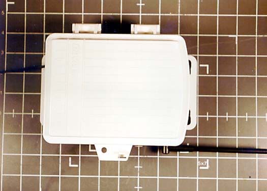
Click to zoom
Application Details
- Equipment Class
- DXX - Part 15 Low Power Communication Device Transmitter
- Date of Grant
- Jan 04, 2001
- Application Purpose
- Original Equipment
- Date of Application
- Jan 04, 2001
- Equipment Note
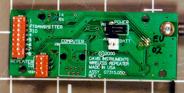
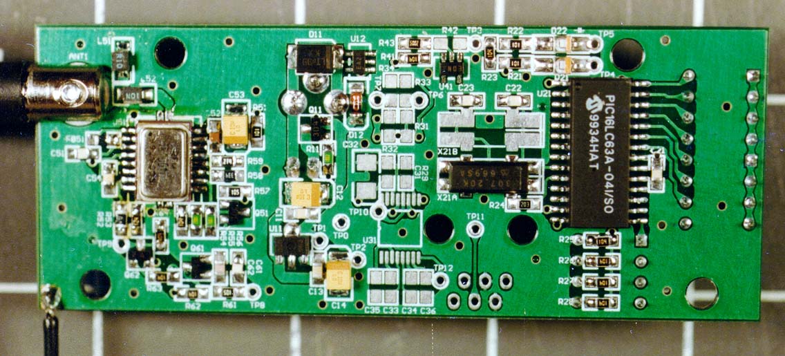
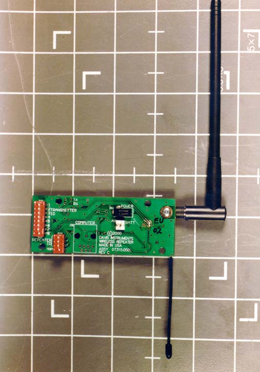
- Wireless Repeaters 7624 & 7625
- Frequency Range
- 916.00000000 - 917.00000000
- Company
- Davis Instruments
- Country
- United States
Documents & Files
Document Text
Text extracted from the exhibit documents filed with the FCC. Open a document above to read the original.
Users Manual
Product # 7624 & 7625 WI R E L E S SRE P E A T E R W I T HSO L A R O RA C - PO W E R The Wireless Repeater receives data from any DavisTalk™ compatible trans- mitter and re-transmits it to any DavisTalk™ compatible receiver. The repeater extends the transmission range and improves reception between the transmit- ter and the receiver. Each repeater has a transmitting and receiving range of between 100' to 1500' (30 to 450 m) depending upon the terrain. The repeater can listen for up to 8 different transmitter signals and can pass those signals on to another repeater or to any number of receivers. Note:The Wireless Repeater operates on a low power frequency that does not require an FCC license. The repeater’s flexibility allows you to put together your weather system in a number of different ways. The most common setup is to install the repeater in between a transmitter and a receiver to improve reception. Another possibility is to install a chain of up to 8 repeaters to carry the transmitter’s signal over a longer distance, or around obstacles. And a third option is to establish a network of weather stations by linking the chain of repeaters to up to 8 different wireless stations. This manual describes three different setup options in separate sections based on how many repeaters and transmitters you plan to install. FThe first section, “Single Transmitter, Single Repeater Installation” on page 3, discusses the most common and simplest installation—that of one transmitter, one repeater and one or more receivers. FThe second section, “Daisy-Chain Installation (Multiple Repeaters)” on page 10, discusses daisy-chaining up to 8 repeaters in succession to increase the range between a single transmitter and one or more receivers. FAnd the third section, “Network Installation (Multiple Transmitters)” on page 12, discusses setting up a complex network of transmitters, repeaters, and receivers. These setup instructions apply whether you have a solar-powered or an AC-powered repeater. Page 2Wireless Repeater CO M P O N E N T S The Wireless Repeater includes the following components. Please be sure you have everything you need for either the AC-powered or the solar-powered model. Wireless Repeater Components TO O L SA N DMA T E R I A L S You may need the following tools and materials for either the AC-powered or solar-powered model. FAdjustable Wrench FMedium Flat Head Screwdriver FMedium Phillips Screwdriver FCompass or Local Area Map FPencil or Other Pointed Object BE F O R EBE G I N N I N G... FOpen the shelter door by gently pressing the friction clasp so the catch disen- gages. Single Transmitter, Single Repeater InstallationPage 3 SI N G L ETR A N S M I T T E R, SI N G L ERE P E A T E RIN S T A L L A T I O N If you have just one DavisTalk™ transmitter and just one repeater, simply follow the instructions below to install your system. If you have a more complex setup that involves multiple repeaters or multiple transmitters within 1500' (450 m) of each other, see “Advanced Installations” on page 10. Setting up the Repeater The repeater is pre-set by the factory to listen for a transmitter whose ID code is also set to the factory default (ID #1). If you have not reset your transmitter’s ID code from the factory default, then your repeater should pick up your trans- mitter’s signal automatically and you can skip to “Choosing a Location” on page 4. If you changed the Transmitter ID code to one of the 7 other optional dip- switch settings, you need to set the repeater to listen for that ID code. To do so, first find your current transmitter settings. For stations that do not use dip- switch settings, refer to the station installation manual. For other transmitters, you can find the current transmitter settings by looking at the position of the first three dip-switches. TRANSMITTER DIP-SWITCHES Next match the ON/OFF settings to the Transmitter ID code in your transmit- ter’s table. Here’s the transmitter ID code table for a typical transmitter. Finally, set your repeater to listen for that transmitter signal by flipping the appropriate dip-switch on your repeater to the ON position. Make sure all other dip-switches are in the OFF position. TRANSMITTER ID CODE DIP-SWITCH 1DIP-SWITCH 2DIP-SWITCH 3DIP-SWITCH 4 #1 (default) offoffoff The position of this dip- switch is not part of the ID code. #2offoffON #3offONoff #4offONON #5ONoffoff #6ONoffON #7ONONoff #8ONONON Page 4Wireless Repeater CAUTION:Use the larger white numbers (1-8) printed on the green board to indicate which dip- switch belongs to which Transmitter ID code. Smaller numbers printed by default on the switch itself may not agree. REPEATER DIP-SWITCHES TO SELECT TRANSMITTER Choosing a Location The range of the radio transmission depends on several factors. Position the repeater as close to the transmitter and receiver as possible for best results. Note: Given the maximum ranges below, the repeater may need to be somewhat closer to the receiver than to the transmitter. Typical maximum ranges between the transmitter and the repeater: FLine of Sight: 1500 feet (450 m) FThrough Walls and Ceilings: 700 feet (225 m) FThrough Trees and Foliage: 700 feet (225 m) Typical maximum ranges between the repeater and the receiver: FLine of Sight: 400 feet (120 m) FThrough Walls and Ceilings: 100 to 200 feet (30 to 60 m) FThrough Trees and Foliage: 100 to 200 feet (30 to 60 m) AC-Powered Repeaters Look for a sheltered location with access to an AC-power outlet. For example, you could mount the repeater in a room or garage. Single Transmitter, Single Repeater InstallationPage 5 Solar-Powered Repeaters Look for a location where you can position the solar panel to receive maxi- mum exposure to the sun’s rays as follows: FThe solar panel works best when the surface of the panel receives full sunlight. Mount the panel away from fences, buildings, trees or other obstructions that may cast shadows over the panel. FThe solar panel should be mounted facing south in t…
Text truncated - open the document above for the full version.
ID Label/Location Info
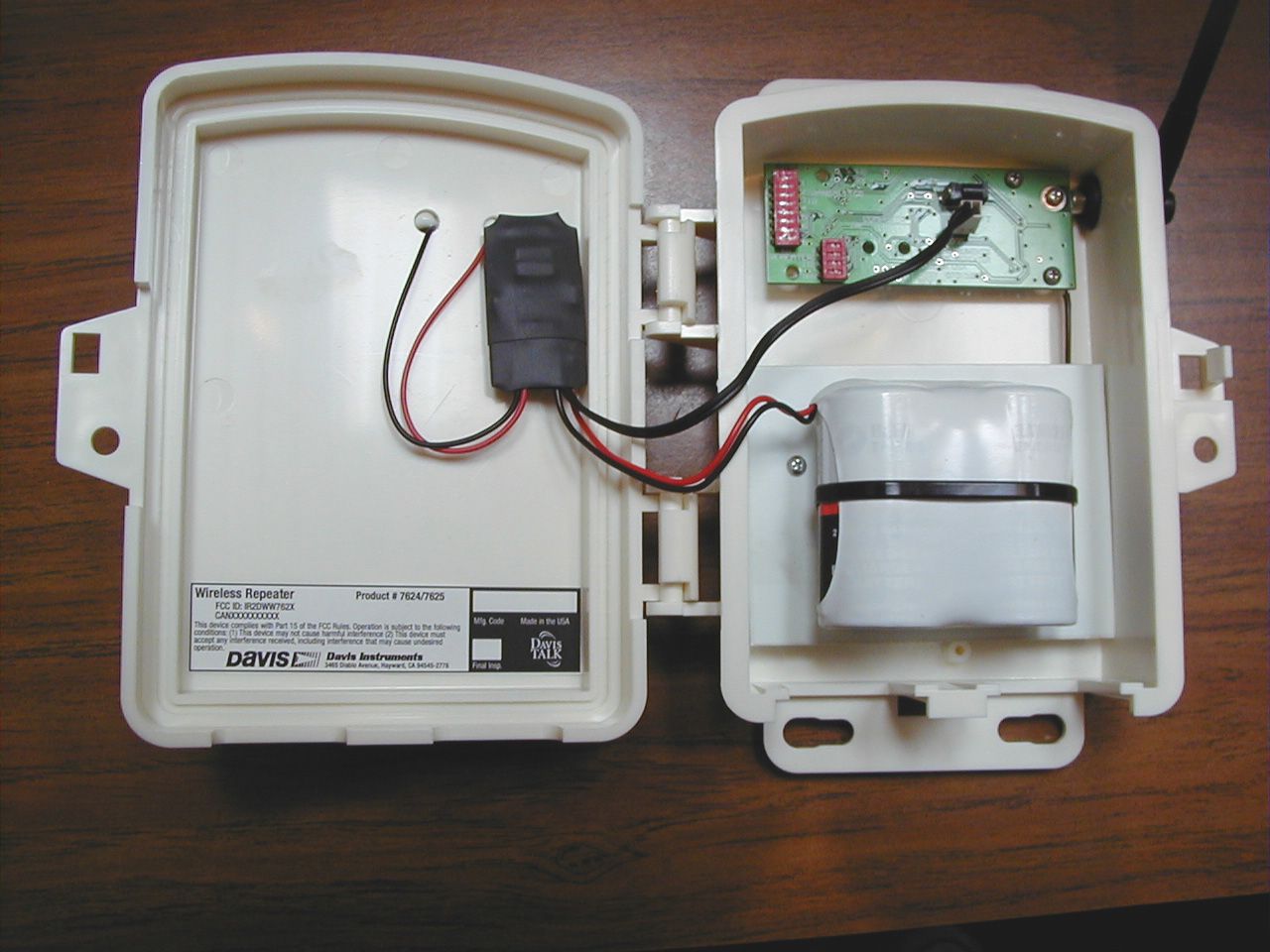
Wireless Repeater FCC ID: IR2DWW762X Product # 7624/7625 This device complies with Part 15 of the FCC Rules. Operation is subject to the following conditions: (1) This device may not cause harmful interference (2) This device must accept any interference received, including interference that may cause undesired operation. 3465 Diablo Avenue, Hayward, CA 94545-2778 Mfg. CodeMade in the USA Final Insp. CANXXXXXXXXXX
Operational Description
D avis In strume nts • 3465 Diablo Ave., Hayward, CA 94545, U.S.A. (510) 732-9229 • FAX: (510) 732-9188 • http://www.davisnet.com To Whom It May Concern: The Davis Instruments Corp. 7624/7625 Wireless Repeater has the following characteristics: RF rating in Watts: < 1mW Frequency Range:916.5 MHz ± 200 kHz Operation: The Davis Instruments Corp. 7624/7625 Wireless Repeater extends the range of other low-power compatible transmitters. Commonly, users place the Wireless Repeater between the 6320 Vantage Pro ISS and the 6310 Vantage Pro Console. The repeater receives weather data packets and retransmits them using the same OOK modulation scheme and frequency as the received signal. It can repeat up to 8 different transmitters; the minimum transmission period is every 2.5 seconds. Circuitry:The 7624/7625 Wireless Repeater uses surface mount components surrounding a PIC microcontroller running at 76 kHz and a TR1000 transceiver chip made by RF Monolithics. Antenna & Ground System: The 7624/7625 Wireless Repeater uses a ¼ wavelength antenna with no ground system other than the circuit board. Block and circuit diagrams are supplied as separate files.
Test Report
Page 1 of 38 Report No: FC00-100A ADDENDUM TO TEST REPORT FC00-100 FOR THE WIRELESS REPEATERS, 7624 & 7625 FCC PART 15 SUBPART C SECTION 15.249 COMPLIANCE DATE OF ISSUE: DECEMBER 22, 2000 PREPARED FOR: Davis Instruments 3465 Diablo Avenue Hayward, CA 94545, USA W.O. No: 75121 PREPARED BY: Joyce Walker CKC Laboratories, Inc. 5473A Clouds Rest Mariposa, CA 95338 Date of test: August 23-25, 2000 Report No: FC00-100A DOCUMENTATION CONTROL: _____________________________ Tracy Phillips Documentation Control Supervisor CKC Laboratories, Inc. APPROVED BY: _____________________________ Dennis Ward Director of Laboratories CKC Laboratories, Inc. This report contains a total of 38 pages and may be reproduced in full only. Partial reproduction may only be done with the written consent of CKC Laboratories, Inc. Page 2 of 38 Report No: FC00-100A TABLE OF CONTENTS Administrative Information ............................................................................................. 3 Summary Of Results........................................................................................................ 4 Equipment Under Test (EUT) Description...................................................................... 4 Measurement Uncertainty................................................................................................ 4 EUT Operating Frequency............................................................................................... 4 Peripheral Devices ........................................................................................................... 5 Report Of Measurements................................................................................................. 6 Table 1: Fundamental Emission Levels............................................................... 6 Table 2: Six Highest Spurious Emission Levels ................................................. 7 Table 3: Spurious Emissions Level Above 1 GHz .............................................. 8 Table 4: Six Highest Conducted Emission Levels .............................................. 9 Table A: List Of Test Equipment .................................................................................... 10 EUT Setup .......................................................................................................................11 Test Instrumentation And Analyzer Settings................................................................... 12 Table B: Analyzer Bandwidth Settings Per Frequency Range............................ 12 Spectrum Analyzer Detector Functions............................................................... 13 Peak ......................................................................................................... 13 Quasi-Peak............................................................................................... 13 Average.................................................................................................... 13 Test Methods ...................................................................................................................14 Radiated Emissions Testing................................................................................. 14 Conducted Emissions Testing ............................................................................. 15 Transmitter Characteristics.............................................................................................. 15 Occupied Bandwidth ........................................................................................... 15 Power Output FCC Part 15.249 (a) ................................................................................. 15 Sample Calculations ........................................................................................................ 16 Appendix A: Information About The Equipment Under Test......................................... 17 I/O Ports............................................................................................................... 18 Crystal Oscillators ............................................................................................... 18 Printed Circuit Boards ......................................................................................... 18 Required EUT Changes To Comply.................................................................... 18 Equipment Configuration Block Diagram - Radiated ......................................... 19 Equipment Configuration Block Diagram - Conducted ...................................... 20 Equipment Configuration Block Diagram - Radiated ......................................... 21 Photograph Showing Radiated Emissions ........................................................... 22 Photograph Showing Radiated Emissions ........................................................... 23 Photograph Showing Conducted Emissions........................................................ 24 Photograph Showing Conducted Emissions........................................................ 25 Photograph Showing Radiated Emissions ........................................................... 26 Photograph Showing Radiated Emissions ........................................................... 27 Appendix B: Measurement Data Sheets .......................................................................... 28 Occupied Bandwidth Plot.................................................................................... 29 Page 3 of 38 Report No: FC00-100A CKC Laboratories, Inc. has Certificates of Accreditation from the following agencies: DATech (Germany); A2LA (USA); FCC (USA); VCCI (Japan); BSMI (Taiwan); HOKLAS (Hong Kong). CKC Laboratories, Inc. has Letters of Acceptance through an MRA for the following agencies: ACA/NATA (Australia); SABS (South Africa); SWEDAC (Sweden); TUV Rheinland-Germany; TUV Rheinland- Korea; TUV Rheinland-Russia; Radio Communications Agency (RA); NEMKO (Norway). ADMINISTRATIVE INFORMATI…
Text truncated - open the document above for the full version.
Test Setup Photos
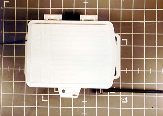
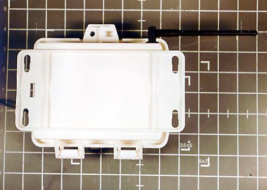
Page 22 of 38 Report No: FC00-100A PHOTOGRAPH SHOWING RADIATED EMISSIONS Radiated Emissions - Front View Page 23 of 38 Report No: FC00-100A PHOTOGRAPH SHOWING RADIATED EMISSIONS Radiated Emissions - Back View Page 24 of 38 Report No: FC00-100A PHOTOGRAPH SHOWING CONDUCTED EMISSIONS Conducted Emissions - Front View Page 25 of 38 Report No: FC00-100A PHOTOGRAPH SHOWING CONDUCTED EMISSIONS Conducted Emissions - Back View Page 26 of 38 Report No: FC00-100A PHOTOGRAPH SHOWING RADIATED EMISSIONS Radiated Emissions - Front View Multiple Units Page 27 of 38 Report No: FC00-100A PHOTOGRAPH SHOWING RADIATED EMISSIONS Radiated Emissions - Back View Multiple Units
Contact Information
Applicant
Bruce Walter(Sr Design Engineer)
Technical Contact
CKC Laboratories Inc.Tracy Phillips
[email protected]1-800-500-4362
5473A Clouds Rest · Mariposa, California · United States
Non-Technical Contact
CKC Laboratories Inc.Joyce Walker
[email protected]1-800-500-4362
Test Firm
CKC Laboratories, Inc.Steve Behm
Technical Specifications
| # | Rule Parts | Frequency Range | Power Output |
|---|---|---|---|
| 1 | 15C | 916 MHz - 917 MHz | - |
Other Applications from Davis Instruments
IR2DWW6313U
Jan 03, 2023WeatherLink Console
Equipment Class
DTS - Digital Transmission System
IR2DWW765Y
Jun 09, 2005Vantage Pro 2 Wireless Repeater
Equipment Class
DSS - Part 15 Spread Spectrum Transmitter
IR2DWW6345
Mar 13, 2005Measurement Station
Equipment Class
DSS - Part 15 Spread Spectrum Transmitter
IR2DWW6312
Sep 29, 2004Integrated Vantage Pro 2 Console.
Equipment Class
DSS - Part 15 Spread Spectrum Transmitter
IR2DWW6328
Sep 29, 2004Integrated Sensor Suite 2 with SPARS
Equipment Class
DSS - Part 15 Spread Spectrum Transmitter