IR5DA05IMHandheld Computer
MilDef Crete Inc.
Click to zoom
Application Details
- Equipment Class
- PCE - PCS Licensed Transmitter held to ear
- Date of Grant
- Jul 01, 2007
- Application Purpose
- Original Equipment
- Date of Application
- May 03, 2007
- Equipment Note
- Handheld Computer
- Frequency Range
- 1850.20000000 - 1909.97000000
- Company
- MilDef Crete Inc.
- Country
- Taiwan
Documents & Files
Document Text
Text extracted from the exhibit documents filed with the FCC. Open a document above to read the original.
Users Manual
HANDHELD COMPUTER DA05 Pocket PC Quick Start Guide Copyright © 2007 All rights reserved. No part of this publication may be reproduced, transmitted, transcribed, stored in a retrieval system, or translated into any language, or computer language, in any form, or by any means, electronic, mechanical, magnetic, optical, chemical, or other, without the prior written permission of the manufacturer. The manufacture reserves the right to revise this publication and to make changes from time to time in the contents hereof without obligation to notify any person of such revision or changes. The manufacturer makes no representations or warranties, either expressed or implied, with respect to the contents hereof and specifically disclaims any warranties as to merchantability or fitness for any particular purpose. Any of the manufacturer's software described in this manual is sold or licensed "as is". Should the programs prove defective following their purchase, the buyer (and not the manufacturer, its distributor, or its dealer), assumes the entire cost of all necessary servicing, repair and any incidental or consequential damages resulting from any defect in the software. Trademark Acknowledgments IBM, PC are registered trademarks of International Business Machines Corp. Microsoft, Windows CE, Pocket PC, and Windows Mobile are registered trademarks of Microsoft Corp. Intel, Bulverde are the registered trademarks of Intel Corp. All product and company names are trademar ks or registered trademarks of their respective holders. EMC and Safe ty Notice Federal Communications Commission Ra dio Frequency Interference Statement This equipment generates, uses, and can radiate radio frequency energy and if not installed and used in accordance with the in structions, may cause interference to radio communications. This equipment has been tested and found to comply with the limits for a class B digital device, pursuant to part 15 of the FCC Rules. These limits are designed to provide reasonable protection against harmful interference in a residential installation. This equipment generates, uses and can radiate radio frequency energy and, if not installed and used in accordance with the instructions, may cause harmful interference to radio communications. However, there is no guarantee that interference will not occur in a particular installation. If this equipment does cause harmful interference to radio or television reception, which can be determined by turning the equipment off and on, the user is encouraged to try to corr ect the interference by one or more of the following measures: ---Reorient or relocate the receiving antenna. ---Increase the separation between the equipment and receiver. ---Connect the equipment into an outlet on a circuit different from that to which the receiver is connected. ---Consult the dealer or an experienced radio/TV technician for help. This Transmitter must not be co-located or operating in conjunction with any other antenna or transmitter. Any changes or modifications (including the antennas) made to this device that are not expressly approved by the manufacturer may void the user’s authority to operate the equipment. This equipment complies with FCC RF radiation exposure limits set forth for an uncontrolled environment. To maintain compliance with FCC RF exposure compliance requirements, avoid direct contact to the transmitting antenna during transmitting. Countermeasures if interference occurs You are encouraged to do the followi ng if interference occurs while you are operating the device: 1. Turn OFF the unit and unplug the AC adapter from the outlet to see if the interference disappears. 2. Connect the AC adapter to the outlet in another room and check if the interference still exists. 3. Use an outlet that is far away from the interfered appliance. 4. Re-orient your computer in resp ect to the interfered appliance to see if there is improvement. If all of these failed, please call your dealer for help. CE This equipment complies with the requirements set out in the Council Direction on the Approximation of th e laws of the Member States relating to Electromagnetic Co mpatibility (89/336/EEC). For the evaluation regarding the electromagnetic compatibility, the following standards were applied: EN55022 +A2:2003 Class B EMI Conduction and Radiation EN61000-3-2 Harmonics EN61000-3-3 +A1:2001 Flicker (V oltage fluctuation) EN55024 EMS EN61000-4-2 +A2:2001 ESD EN61000-4-3 +A1:2002 RS EN61000-4-4 +A2:2001 EFT EN61000-4-5 +A1:2001 Surge EN61000-4-6 +A1:2001 CS EN61000-4-8 Power-Frequency Magnetic Field EN61000-4-11 +A1:2001 Voltage Dips and Voltage Interruptions LVD EN60950-1 :2001 ETSI EN301 489-01 V1.4.1 EMC Standards for Radio Equipment ETSI EN 301 489-17 1.2.1 EMC Standards for 2.4GHz Wideband Transmission Systems) ETSI EN 300 328-2 V1.2.1 EMC Standards for Using Spread Spectrum Modulation Techniques UL, TÜV AC Adapter (EN60950 LVD is included in TÜV) E-Mark Registered e13 Material Safety a nd Recycling Notice All materials used in the construction of this unit are recyclable or environmentally friendly. No mercury, cadmium, CFC or related materials were used in the manufacturing process or inside the product. Please recycle the packing materials, and at the end of the unit's life, all other materials in accordance with the local regulations. Please refer “ Materials and Recycling ” for the contents of the materials. CONTENTS GETTING ST ARTED ............................................................................................... 1 U NPACKING .............................................................................................................. 1 Q UICK C HECK .......................................................................................................... 2 C ONTROLS , I NDICATORS , AND P ORTS ....................................................................... 3 O PERATING E NVIRONMENT AND R UGGEDNESS .........................................…
Text truncated - open the document above for the full version.
External Photos
Compliance Certification Services Inc. Report No.: 61108002 Date of Issue: April 17, 2007 Page 1 Total Page: 22 Rev. 00 EXTERNAL PHOTOGRAPHS OF EUT Compliance Certification Services Inc. Report No.: 61108002 Date of Issue: April 17, 2007 Page 2 Rev.00 Compliance Certification Services Inc. Report No.: 61108002 Date of Issue: April 17, 2007 Page 3 Rev.00 Compliance Certification Services Inc. Report No.: 61108002 Date of Issue: April 17, 2007 Page 4 Rev.00 Compliance Certification Services Inc. Report No.: 61108002 Date of Issue: April 17, 2007 Page 5 Rev.00 Compliance Certification Services Inc. Report No.: 61108002 Date of Issue: April 17, 2007 Page 6 Rev.00 Compliance Certification Services Inc. Report No.: 61108002 Date of Issue: April 17, 2007 Page 7 Rev.00 Compliance Certification Services Inc. Report No.: 61108002 Date of Issue: April 17, 2007 Page 8 Rev.00 Compliance Certification Services Inc. Report No.: 61108002 Date of Issue: April 17, 2007 Page 9 Rev.00
Internal Photos
Compliance Certification Services Inc. Report No.: 61108002 Date of Issue: April 17, 2007 Page 10 Rev.00 INTERNAL PHOTOGRAPHS OF EUT Bluetooth Antenna Compliance Certification Services Inc. Report No.: 61108002 Date of Issue: April 17, 2007 Page 11 Rev.00 WLAN Antenna Compliance Certification Services Inc. Report No.: 61108002 Date of Issue: April 17, 2007 Page 12 Rev.00 Compliance Certification Services Inc. Report No.: 61108002 Date of Issue: April 17, 2007 Page 13 Rev.00 Compliance Certification Services Inc. Report No.: 61108002 Date of Issue: April 17, 2007 Page 14 Rev.00 Compliance Certification Services Inc. Report No.: 61108002 Date of Issue: April 17, 2007 Page 15 Rev.00 Bluetooth Module Compliance Certification Services Inc. Report No.: 61108002 Date of Issue: April 17, 2007 Page 16 Rev.00 Compliance Certification Services Inc. Report No.: 61108002 Date of Issue: April 17, 2007 Page 17 Rev.00 Compliance Certification Services Inc. Report No.: 61108002 Date of Issue: April 17, 2007 Page 18 Rev.00 Compliance Certification Services Inc. Report No.: 61108002 Date of Issue: April 17, 2007 Page 19 Rev.00 Compliance Certification Services Inc. Report No.: 61108002 Date of Issue: April 17, 2007 Page 20 Rev.00 Compliance Certification Services Inc. Report No.: 61108002 Date of Issue: April 17, 2007 Page 21 Rev.00 WLAN Module Compliance Certification Services Inc. Report No.: 61108002 Date of Issue: April 17, 2007 Page 22 Rev.00 GSM Antenna
Parts List/Tune Up Info
1 Approval Sheet l Product Type l GPRS / Bluetooth Antenna l Model Number l Crete DA05 l Revision l X00 l Part No. / Yageo / GPRS-BT Antenna l CAN4313573022501B Yageo (Taiwan) Ltd. 16, West 3rd Street, N.E.P.Z Kaohsiung, 811 Taiwan, R.O.C Yageo Electronics (China) Co, Ltd No. 10, Zhu Yuan Road, Suzhou New District, Suzhou, PRC R00 Sept. 20, 06 R01 Oct. 03, 06 R02 Oct 20, 06 Multi Band Antenna with Cable & Connector CAN4313573022501B BY / Teresa Chang DATE / Oct. 3, 2006 2 Table of Contents 1. Specifications 1.1 Specifications 1.2 Antenna Dimension / Cable Length / Cable Diameter 1.3 Packing Spec. 1.4 Antenna Picture 2. Test Methodology 2.1 Test Equipment 2.2 Test Setup 2.2.1 Frequency Range 2.2.2 Antenna Configuration 2.2.3 VSWR 2.2.4 Radiation Pattern and Gain 3. Performance Data 3.1 VSWR in the Fixture 3.2 Radiation Pattern and Gain 4. Antenna Drawing 5. Reliability Data for Antenna Patch 6. Ordering Information: Yageo Ordering P/N Code 7. Revision Control 3 1. Specifications 1.1 Specifications for Bluetooth Antenna Frequency Range (GHz) 2.40 ~ 2.50 VSWR 2.50 max Peak Gain (dBi) -1.77 MiniPCI Connector Hirose U.FL (or Compatible) Impedance 50Ω Operating Temperature -40~9 0°C Maximum Power 1W Polarization Linear Radiation Pattern Omni-directional 1.2 Specifications for GPRS Antenna Frequency Range (MHz) 880 ~ 960 for GSM900 Band 1710 ~ 2170 for GSM1800/1900/IMT2000 Band Peak Gain (dBi) -3.07 for GSM900 Band -0.13 for GSM1800/1900/IMT2000 Band MiniPCI Connector IPex or Hirose Impedance 50Ω Operating Temperature -40~90°C Maximum Power 1W Polarization Linear Radiation Pattern Omni-directional 1.3 Antenna Dimension / Cable Length / Cable Diameter Product Crete /DA05 Antenna Bluetooth Antenna Cable Length=77mm, Color=White / OD=1.13mm Product Crete /DA05 Antenna GPRS Antenna Cable Length=52mm, Color=Black / OD=1.13mm 4 1.4 Packing Spec. Product For Example Inner Tray 60 Carton Box 265*100 1.5 Antenna Picture 2. Test Methodology 2.1 Test Equipment The equipment for the antenna measurement we used is as follows. A. Agilent 8753ET / 8719D Network Analyzer to measure the VSWR and input impedance. B. Three-dimensional anechoic chamber to measure the gain (Standard dipole and horn were used to calibrate the chamber) C. Digital caliper to measure the dimensions. D. Climatic chamber for mechanical tests. 2.2 Test Setup 2.2.1 Frequency Range B B l l u u e e t t o o o o t t h h : : 2 2 . . 4 4 0 0 ~ ~ 2 2 . . 5 5 0 0 G G H H z z , , G G P P R R S S : : 8 8 8 8 0 0 ~ ~ 9 9 6 6 0 0 M M H H z z , , 1 1 7 7 1 1 0 0 ~ ~ 2 2 1 1 7 7 0 0 M M H H z z 2.2.2 Antenna Configuration The antenna basically has two parts; the stamping and the cable assembly with the connector on one side. The detailed drawing is attached. 2.2.3 VSWR The VSWR is measured with Agilent 8753ET / 8719D network analyzer. All the measurements are performed with the customer provided fixture. Figure 1 shows the schematic diagram for measuring VSWR. 5 Test port cable Figure 1. The schematic diagram for measuring VSWR 2.2.4 Radiation Pattern and Gain The radiation pattern must have the omni-directional characteristic in both positions. The radiation pattern measurements are performed in the three- dimensional anechoic chamber. The chamber provides less than –30dB reflectivity from 800MHz through 8GHz. The chamber is calibrated using both standard dipole and horn antenna. The gain here is expressed as dBi that standardizes the isotropic antenna. The gain measurements are also performed in the same chamber described previously. Figure 2 shows the schematic diagram for measuring radiation pattern and gain. Figure 2. The schematic diagram for measuring radiation pattern and gain D.U.T Agilent 8753ET Network Analyzer 2D Anechoic Chamber Probe array Controller RF Unit (0.4 ~ 6GHz) Primary Synthesizer Auxiliary Synthesizer Motion Controller Data Acquisition & Processing PC 6 3. Performance Data VSWR Measurement VSWR of BLUETOOTH (White) VSWR of GPRS (Black) 7 Radiation Pattern -BLUETOOTH (White Cable) Horizontal Vertical H+V Horizontal Vertical H+V Horizontal Vertical H+V Horizontal Vertical H+V Horizontal Vertical H+V Horizontal Vertical H+V -40 -30 -20 -10 0 5 90° 180° 270° 0° -40 -30 -20 -10 0 5 90° 180° 270° 0° -40 -30 -20 -10 0 5 90° 180° 270° 0° -40 -30 -20 -10 0 5 90° 180° 270° 0° -40 -30 -20 -10 0 5 90° 180° 270° 0° -40 -30 -20 -10 0 5 90° 180° 270° 0° -7.37 Hori + Vert Avg. Gain (dBi) -4.92 Vertical Peak Gain (dBi) -5.45 Horizontal Peak Gain (dBi) 2400MHz Center Frequency -7.37 Hori + Vert Avg. Gain (dBi) -4.92 Vertical Peak Gain (dBi) -5.45 Horizontal Peak Gain (dBi) 2400MHz Center Frequency -7.26 Hori + Vert Avg. Gain (dBi) -4.96 Vertical Peak Gain (dBi) -7.91 Horizontal Peak Gain (dBi) 2450MHzCenter Frequency -7.26 Hori + Vert Avg. Gain (dBi) -4.96 Vertical Peak Gain (dBi) -7.91 Horizontal Peak Gain (dBi) 2450MHzCenter Frequency -5.14 Hori + Vert Avg. Gain (dBi) -1.77 Vertical Peak Gain (dBi) -8.79 Horizontal Peak Gain (dBi) 2500MHzCenter Frequency -5.14 Hori + Vert Avg. Gain (dBi) -1.77 Vertical Peak Gain (dBi) -8.79 Horizontal Peak Gain (dBi) 2500MHzCenter Frequency -GPRS(Black Cable) 880MHz 900MHz 8 940MHz 960MHz 1710MHz 1750MHz 1840MHz 1880MHz 9 1960MHz 2140MHz 2170MHz 10 4. Antenna Drawing Bluetooth (White) 77 +/-3 mm GPRS (Black) 52 +/- 3 mm 11 5. Reliability Data For Antenna Patch (Reference To IEC) IEC 384-10/ CECC 32 100 CLAUSE IEC 60068-2 TEST METHOD TEST PROCEDURE REQUIREMENTS 4.12 4(Na) Rapid change of temperature -40 °C (30 minutes) to +90 °C (30 minutes); 5 cycles No visible damage Central Freq. Change ± 6% 4.14 3(Ca) Damp heat 500 ± 12 hours at 40 °C; 90 to 95 % RH No visible damage 2 hours recovery Central Freq. Change ± 6% 4.15 Endurance 500 ± 12 hours at 90 ° C; No visible damage 2 hours recovery Central Freq. Change ± 6% 6. Ordering Information: Yageo Ordering P/N Code The antennas may be ordered by using the Yageo P/N ordering code. These code numbers can be determined by the following rules: CAN4313 5 43 01 250 1B F C…
Text truncated - open the document above for the full version.
RF Exposure Info
Date/Time:4/2/2007 9:53:11 AM Test Laboratory: Compliance Certification Services Inc. D835V2-SN 4d015-Head DUT: Dipole 835 MHz; Type: D835V2; Serial: 4d015 Communication System: CW 835; Frequency: 835 MHz;Duty Cycle: 1:1 Medium parameters used (interpolated): f = 835 MHz; ı = 0.894 mho/m; İ r = 41.2; ȡ = 1000 kg/m 3 Phantom section: Flat Section Air Temperature:24.1 deg C;Liquid Temperature:23.1 deg C Area Scan Find Secondary Maximum Within 2dB and with a peak SAR value greater than 0.0012W/kg DASY4 Configuration: z Probe: EX3DV3 - SN3531; ConvF(10.57, 10.57, 10.57); z Sensor-Surface: 2.5mm (Mechanical Surface Detection) z Electronics: DAE3 Sn500; Calibrated: 8/23/2006 z Phantom: SAM 34; Type: SAM V4.0; Serial: TP-1150 z Measurement SW: DASY4, V4.7 Build 53; Postprocessing SW: SEMCAD, V1.8 Build 172 d=10mm, Pin=250mW/Area Scan (7x7x1): Measurement grid: dx=15mm, dy=15mm Maximum value of SAR (measured) = 2.91 mW/g d=10mm, Pin=250mW/Zoom Scan (5x5x7)/Cube 0: Measurement grid: dx=7.5mm, dy=7.5mm, dz=5mm Reference Value = 52.5 V/m; Power Drift = -0.018 dB Peak SAR (extrapolated) = 3.81 W/kg SAR(1 g) = 2.29 mW/g; SAR(10 g) = 1.38 mW/g Maximum value of SAR (measured) = 3.08 mW/g d=10mm, Pin=250mW/Z Scan (1x1x21): Measurement grid: dx=20mm, dy=20mm, dz=5mm Maximum value of SAR (measured) = 2.00 mW/g Page1 Page2 Date/Time: 4/4/2007 11:11:12 AM Test Laboratory: Compliance Certification Services Inc. D835V2-SN 4d015-Body DUT: Dipole 835 MHz; Type: D835V2; Serial: 4d015 Communication System: CW 835; Frequency: 835 MHz;Duty Cycle: 1:1 Medium parameters used (interpolated): f = 835 MHz; ı = 0.931 mho/m; İ r = 55.2; ȡ = 1000 kg/m 3 Phantom section: Flat Section Air Temperature:24.3 deg C;Liquid Temperature:23.3 deg C Area Scan Find Secondary Maximum Within 2dB and with a peak SAR value greater than 0.0012W/kg DASY4 Configuration: z Probe:EX3DV3 - SN3531; ConvF(10.96, 10.96, 10.96); z Sensor-Surface: 2.5mm (Mechanical Surface Detection)Sensor-Surface: 0mm (Fix Surface) z Electronics: DAE3 Sn500; Calibrated: 8/23/2006 z Phantom: SAM 34; Type: SAM V4.0; Serial: TP-1150 z Measurement SW: DASY4, V4.7 Build 53; Postprocessing SW: SEMCAD, V1.8 Build 172 d=10mm, Pin=250mW/Area Scan (7x7x1): Measurement grid: dx=15mm, dy=15mm Maximum value of SAR (measured) = 3.05 mW/g d=10mm, Pin=250mW/Zoom Scan (5x5x7)/Cube 0: Measurement grid: dx=7.5mm, dy=7.5mm, dz=5mm Reference Value = 54.1 V/m; Power Drift = -0.006 dB Peak SAR (extrapolated) = 3.89 W/kg SAR(1 g) = 2.54 mW/g; SAR(10 g) = 1.64 mW/g Maximum value of SAR (measured) = 3.12 mW/g d=10mm, Pin=250mW/Z Scan (1x1x21): Measurement grid: dx=20mm, dy=20mm, dz=5mm Maximum value of SAR (measured) = 2.13 mW/g Page1 Page2 Date/Time:4/3/2007 11:12:37 AM Test Laboratory: Compliance Certification Services Inc. D1900V2 SN-5d056 Head DUT: Dipole 1900 MHz; Type: D1900V2; Serial: 5d056 Communication System: CW1900; Frequency: 1900 MHz;Duty Cycle: 1:1 Medium parameters used (interpolated): f = 1900 MHz; ı = 1.46 mho/m; İ r = 38.1; ȡ = 1000 kg/m 3 Phantom section: Flat Section Air Temperature:24.0 deg C;Liquid Temperature:23.0 deg C Area Scan Find Secondary Maximum Within 2dB and with a peak SAR value greater than 0.0012W/kg DASY4 Configuration: z Probe:EX3DV3 - SN3531; ConvF(8.52, 8.52, 8.52); z Sensor-Surface: 2.5mm (Mechanical Surface Detection) z Electronics: DAE3 Sn500; Calibrated: 8/23/2006 z Phantom: SAM 12; Type: SAM V4.0; Serial: TP-1150 z Measurement SW: DASY4, V4.7 Build 53; Postprocessing SW: SEMCAD, V1.8 Build 172 Pin=250mW,d=10mm/Area Scan (6x6x1): Measurement grid: dx=15mm, dy=15mm Maximum value of SAR (measured) = 9.55 mW/g Pin=250mW,d=10mm/Zoom Scan (5x5x7)/Cube 0: Measurement grid: dx=7.5mm, dy=7.5mm, dz=5mm Reference Value = 86.9 V/m; Power Drift = -0.023 dB Peak SAR (extrapolated) = 17.6 W/kg SAR(1 g) = 9.41 mW/g; SAR(10 g) = 5.32 mW/g Maximum value of SAR (measured) = 11.3 mW/g Pin=250mW,d=10mm/Z Scan (1x1x21): Measurement grid: dx=20mm, dy=20mm, dz=5mm Maximum value of SAR (measured) = 13.4 mW/g Page1 Page2 Date/Time: 4/5/2007 11:02:44 AM Test Laboratory: Compliance Certification Services Inc. D1900V2 SN-5d056 Body DUT: Dipole 1900 MHz; Type: D1900V2; Serial: 5d056 Communication System: CW1900; Frequency: 1900 MHz;Duty Cycle: 1:1 Medium parameters used: f = 1900 MHz; ı = 1.51 mho/m; İ r = 51.5; ȡ = 1000 kg/m 3 Phantom section: Flat Section Air Temperature:24.3 deg C;Liquid Temperature:23.2 deg C Area Scan Find Secondary Maximum Within 2dB and with a peak SAR value greater than 0.0012W/kg DASY4 Configuration: z Probe: EX3DV3 - SN3531; ConvF(8.43, 8.43, 8.43); z Sensor-Surface: 2.5mm (Mechanical Surface Detection) z Electronics: DAE3 Sn500; Calibrated: 8/23/2006 z Phantom: SAM 12; Type: SAM V4.0; Serial: TP-1150 z Measurement SW: DASY4, V4.7 Build 53; Postprocessing SW: SEMCAD, V1.8 Build 172 Pin=250mW,d=10mm/Area Scan (6x6x1): Measurement grid: dx=15mm, dy=15mm Maximum value of SAR (measured) = 8.29 mW/g Pin=250mW,d=10mm/Zoom Scan (5x5x7)/Cube 0: Measurement grid: dx=7.5mm, dy=7.5mm, dz=5mm Reference Value = 94.7 V/m; Power Drift = -0.035 dB Peak SAR (extrapolated) = 16.2 W/kg SAR(1 g) = 9.34 mW/g; SAR(10 g) = 4.81 mW/g Maximum value of SAR (measured) = 12.6 mW/g Pin=250mW,d=10mm/Z Scan (1x1x21): Measurement grid: dx=20mm, dy=20mm, dz=5mm Maximum value of SAR (measured) = 13.6 mW/g Page1 Page2 Date/Time: 4/2/2007 10:43:23 AM Test Laboratory: Compliance Certification Services Inc. GSM 835-Left Head DA05I DUT: DA05I; Type: Handheld Computer; Serial: N/A Communication System: GSM 850; Frequency: 824.2 MHz;Duty Cycle: 1:8 Medium parameters used (interpolated): f = 824.2 MHz; ı = 0.884 mho/m; İ r = 41.3; ȡ = 1000 kg/m 3 Phantom section: Left Section Air Temperature:24.1 deg C;Liquid Temperature:23.1 deg C Area Scan Find Secondary Maximum Within 2dB and with a peak SAR value greater than 0.0012W/kg DASY4 Configuration: z Probe: EX3DV3 - SN3531; ConvF(10.57, 10.57, 10.57); z Sensor-Surface: 2.5mm (Mechanical Surface Detection) z Electronics: DAE3 Sn500; Calibrated: 8…
Text truncated - open the document above for the full version.
RF Exposure Info
Date/Time: 4/4/2007 1:31:27 PM Test Laboratory: Compliance Certification Services Inc. GSM 850-Body DA05I DUT: DA05I; Type: Handheld Computer; Serial: N/A Communication System: GSM 850; Frequency: 848.8 MHz;Duty Cycle: 1:8 Medium parameters used (interpolated): f = 848.8 MHz; ı = 0.943 mho/m; İ r = 55; ȡ = 1000 kg/m 3 Phantom section: Flat Section Air Temperature:24.3 deg C;Liquid Temperature:23.3 deg C Area Scan Find Secondary Maximum Within 2dB and with a peak SAR value greater than 0.0012W/kg DASY4 Configuration: z Probe: EX3DV3 - SN3531; ConvF(10.96, 10.96, 10.96); z Sensor-Surface: 2.5mm (Mechanical Surface Detection) z Electronics: DAE3 Sn500; Calibrated: 8/23/2006 z Phantom: SAM 34; Type: SAM V4.0; Serial: TP-1150 z Measurement SW: DASY4, V4.7 Build 53; Postprocessing SW: SEMCAD, V1.8 Build 172 GSM Body Front High CH251/Area Scan (9x12x1): Measurement grid: dx=15mm, dy=15mm Maximum value of SAR (measured) = 0.070 mW/g GSM Body Front High CH251/Zoom Scan (5x5x7)/Cube 0: Measurement grid: dx=7.5mm, dy=7.5mm, dz=5mm Reference Value = 8.16 V/m; Power Drift = -0.064 dB Peak SAR (extrapolated) = 0.088 W/kg SAR(1 g) = 0.061 mW/g; SAR(10 g) = 0.041 mW/g Maximum value of SAR (measured) = 0.073 mW/g Page1 Page2 Date/Time: 4/4/2007 1:52:55 PM Test Laboratory: Compliance Certification Services Inc. GSM 850-Body DA05I DUT: DA05I; Type: Handheld Computer; Serial: N/A Communication System: GSM 850; Frequency: 824.2 MHz;Duty Cycle: 1:8 Medium parameters used (interpolated): f = 824.2 MHz; ı = 0.921 mho/m; İ r = 55.3; ȡ = 1000 kg/m 3 Phantom section: Flat Section Air Temperature:24.3 deg C;Liquid Temperature:23.3 deg C Area Scan Find Secondary Maximum Within 2dB and with a peak SAR value greater than 0.0012W/kg DASY4 Configuration: z Probe: EX3DV3 - SN3531; ConvF(10.96, 10.96, 10.96); z Sensor-Surface: 2.5mm (Mechanical Surface Detection) z Electronics: DAE3 Sn500; Calibrated: 8/23/2006 z Phantom: SAM 34; Type: SAM V4.0; Serial: TP-1150 z Measurement SW: DASY4, V4.7 Build 53; Postprocessing SW: SEMCAD, V1.8 Build 172 GSM Body Back Low CH128/Area Scan (9x15x1): Measurement grid: dx=15mm, dy=15mm Maximum value of SAR (measured) = 0.090 mW/g GSM Body Back Low CH128/Zoom Scan (5x5x7)/Cube 0: Measurement grid: dx=7.5mm, dy=7.5mm, dz=5mm Reference Value = 7.77 V/m; Power Drift = -0.051 dB Peak SAR (extrapolated) = 0.106 W/kg SAR(1 g) = 0.078 mW/g; SAR(10 g) = 0.054 mW/g Maximum value of SAR (measured) = 0.093 mW/g Page1 Page2 Date/Time: 4/4/2007 2:15:20 PM Test Laboratory: Compliance Certification Services Inc. GSM 850-Body DA05I DUT: DA05I; Type: Handheld Computer; Serial: N/A Communication System: GSM 850; Frequency: 836.6 MHz;Duty Cycle: 1:8 Medium parameters used (interpolated): f = 836.6 MHz; ı = 0.932 mho/m; İ r = 55.1; ȡ = 1000 kg/m 3 Phantom section: Flat Section Air Temperature:24.3 deg C;Liquid Temperature:23.3 deg C Area Scan Find Secondary Maximum Within 2dB and with a peak SAR value greater than 0.0012W/kg DASY4 Configuration: z Probe: EX3DV3 - SN3531; ConvF(10.96, 10.96, 10.96); z Sensor-Surface: 2.5mm (Mechanical Surface Detection) z Electronics: DAE3 Sn500; Calibrated: 8/23/2006 z Phantom: SAM 34; Type: SAM V4.0; Serial: TP-1150 z Measurement SW: DASY4, V4.7 Build 53; Postprocessing SW: SEMCAD, V1.8 Build 172 GSM Body Back Middle CH190/Area Scan (9x13x1): Measurement grid: dx=15mm, dy=15mm Maximum value of SAR (measured) = 0.073 mW/g GSM Body Back Middle CH190/Zoom Scan (5x5x7)/Cube 0: Measurement grid: dx=7.5mm, dy=7.5mm, dz=5mm Reference Value = 6.83 V/m; Power Drift = -0.028 dB Peak SAR (extrapolated) = 0.087 W/kg SAR(1 g) = 0.064 mW/g; SAR(10 g) = 0.044 mW/g Maximum value of SAR (measured) = 0.074 mW/g Page1 Page2 Date/Time: 4/4/2007 2:33:49 PM Test Laboratory: Compliance Certification Services Inc. GSM 850-Body DA05I DUT: DA05I; Type: Handheld Computer; Serial: N/A Communication System: GSM 850; Frequency: 848.8 MHz;Duty Cycle: 1:8 Medium parameters used (interpolated): f = 848.8 MHz; ı = 0.943 mho/m; İ r = 55; ȡ = 1000 kg/m 3 Phantom section: Flat Section Air Temperature:24.3 deg C;Liquid Temperature:23.3 deg C Area Scan Find Secondary Maximum Within 2dB and with a peak SAR value greater than 0.0012W/kg DASY4 Configuration: z Probe: EX3DV3 - SN3531; ConvF(10.96, 10.96, 10.96); z Sensor-Surface: 2.5mm (Mechanical Surface Detection) z Electronics: DAE3 Sn500; Calibrated: 8/23/2006 z Phantom: SAM 34; Type: SAM V4.0; Serial: TP-1150 z Measurement SW: DASY4, V4.7 Build 53; Postprocessing SW: SEMCAD, V1.8 Build 172 GSM Body Back High CH251/Area Scan (9x12x1): Measurement grid: dx=15mm, dy=15mm Maximum value of SAR (measured) = 0.073 mW/g GSM Body Back High CH251/Zoom Scan (5x5x7)/Cube 0: Measurement grid: dx=7.5mm, dy=7.5mm, dz=5mm Reference Value = 6.73 V/m; Power Drift = -0.002 dB Peak SAR (extrapolated) = 0.085 W/kg SAR(1 g) = 0.063 mW/g; SAR(10 g) = 0.044 mW/g Maximum value of SAR (measured) = 0.077 mW/g Page1 Page2 Date/Time: 4/4/2007 3:03:50 PM Test Laboratory: Compliance Certification Services Inc. GSM 850-Body DA05I DUT: DA05I; Type: Handheld Computer; Serial: N/A Communication System: GSM 850; Frequency: 824.2 MHz;Duty Cycle: 1:8 Medium parameters used (interpolated): f = 824.2 MHz; ı = 0.921 mho/m; İ r = 55.3; ȡ = 1000 kg/m 3 Phantom section: Flat Section Air Temperature:24.3 deg C;Liquid Temperature:23.3 deg C Area Scan Find Secondary Maximum Within 2dB and with a peak SAR value greater than 0.0012W/kg DASY4 Configuration: z Probe: EX3DV3 - SN3531; ConvF(10.96, 10.96, 10.96); z Sensor-Surface: 2.5mm (Mechanical Surface Detection) z Electronics: DAE3 Sn500; Calibrated: 8/23/2006 z Phantom: SAM 34; Type: SAM V4.0; Serial: TP-1150 z Measurement SW: DASY4, V4.7 Build 53; Postprocessing SW: SEMCAD, V1.8 Build 172 co-Location 802.11b+Bt+GSM Body Front Low CH128/Area Scan (9x12x1): Measurement grid: dx=15mm, dy=15mm Maximum value of SAR (measured) = 0.085 mW/g co-Location 802.11b+Bt+GSM Body Front Low CH128/Zoom Scan (5x5x7)/Cube 0: Measurement grid: dx=7.5mm, dy=7.5mm, dz=5mm Refere…
Text truncated - open the document above for the full version.
RF Exposure Info
Compliance Certification Services Inc. Report No: 61108002-SF FCC ID: IR5DA05IM Date of Issue: May 2, 2007 Note: This report shall not be reproduced except in full, without the written approval of Compliance Certification Services Inc. This document may be altered or revised by Compliance Certification Services Inc. personnel only, and shall be noted in the revision section of the document. Page 1 Total Page: 37 Rev. 00 ANSI/IEEE Std. C95.1-1992 In accordance with the requirements of FCC Report and Order: ET Docket 93-62, and OET Bulletin 65 Supplement C FCC SAR TEST REPORT For Handheld Computer Model: DA05I, DA05M, CR05 Trade Name: CReTE Issued to CRETE SYSTEMS INC. 7F, No. 250, Sec. 3, Pei Shen Rd., Shen Keng Hsiang, Taipei County, Taiwan. Issued by Compliance Certification Services Inc. No. 11, Wugong 6th Rd., Wugu Industrial Park, Taipei Hsien, 248 Taiwan. http://www.ccsemc.com.tw [email protected] Compliance Certification Services Inc. Report No.: 61108002-SF Date of Issue: May 2, 2007 Page 2 Rev. 00 TABLE OF CONTENTS 1. CERTIFICATE OF COMPLIANCE (SAR EVALUATION) .............................................................3 2. EUT DESCRIPTION ...........................................................................................................................4 3. REQUIREMENTS FOR COMPLIANCE TESTING DEFINED BY THE FCC ................................5 4. DOSIMETRIC ASSESSMENT SETUP ..............................................................................................5 4.1 MEASUREMENT SYSTEM DIAGRAM.....................................................................................6 4.2 SYSTEM COMPONENTS............................................................................................................7 5. EVALUATION PROCEDURES .........................................................................................................9 6. MEASUREMENT UNCERTAINTY ................................................................................................13 7. EXPOSURE LIMIT ...........................................................................................................................14 8. EUT ARRANGEMENT.....................................................................................................................15 8.1 ANTHROPOMORPHIC HEAD PHANTOM.............................................................................15 8.2 DEFINITION OF THE “CHEEK/TOUCH” POSITION ............................................................16 8.3 DEFINITION OF THE “TILTED” POSITION...........................................................................17 9. MEASUREMENT RESULTS............................................................................................................18 9.1 SYSTEM PERFORMANCE CHECK .........................................................................................18 9.2 TEST LIQUIDS CONFIRMATION............................................................................................20 9.3 EUT TUNE-UP PROCEDURES .................................................................................................22 9.4 SAR MEASUREMENT RESULTS ............................................................................................25 10. EUT PHOTOS....................................................................................................................................33 11. EQUIPMENT LIST & CALIBRATION STATUS............................................................................35 12. FACILITIES .......…
Text truncated - open the document above for the full version.
Contact Information
Applicant
Jonas Hong(Deputy Manager)
Technical Contact
Compliance Certification Services Inc.Kevin Wang
[email protected]886-2-2299-9720
No. 81-1, Lane 210, Bade Rd. 2, Luchu Hsiang, · Taoyuan Hsien · Taiwan
Test Firm
Compliance Certification Services Inc.Kurt Chen
Technical Specifications
| # | Rule Parts | Frequency Range | Power Output | Emission | Tolerance |
|---|---|---|---|---|---|
| 4 | 24E | 1.85 GHz - 1.91 GHz | 301.99 mW | 246KG7W | 90 Hz |
Other Applications from MilDef Crete Inc.
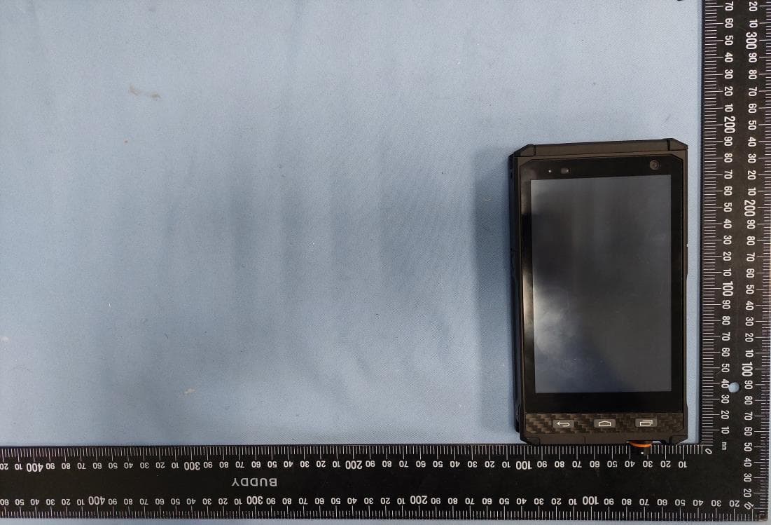
IR5DF10
Apr 12, 2023HANDHELD COMPUTER
Equipment Class
DSS - Part 15 Spread Spectrum Transmitter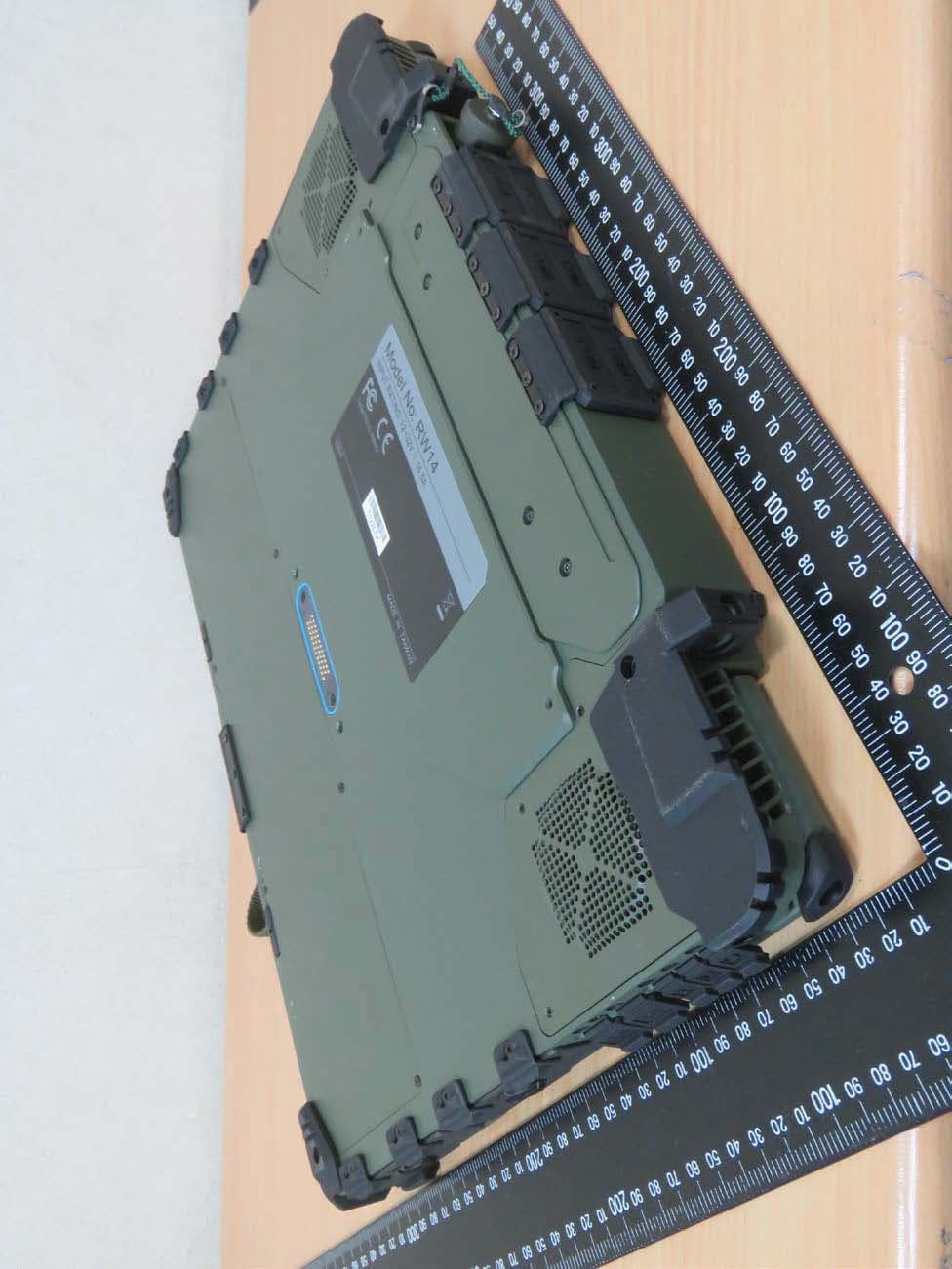
IR5RW14
Mar 16, 2020Notebook computer
Equipment Class
DSS - Part 15 Spread Spectrum Transmitter
IR5DS11
Aug 17, 2015Tablet Computer
Equipment Class
NII - Unlicensed National Information Infrastructure TX
IR5RT10
Jun 29, 2015Notebook Computer
Equipment Class
DSS - Part 15 Spread Spectrum Transmitter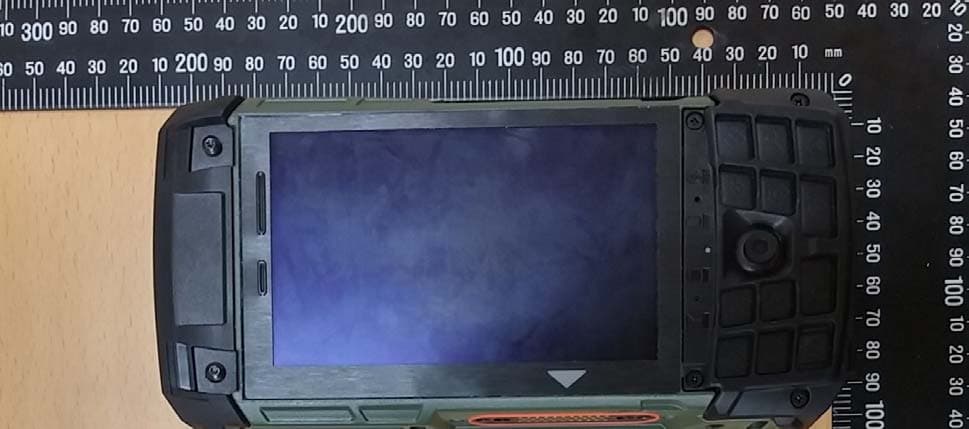
IR5DB7
Apr 09, 2015Handheld Computer
Equipment Class
NII - Unlicensed National Information Infrastructure TX