ISEILRInternational LAR 806A5301
Xmark Corporation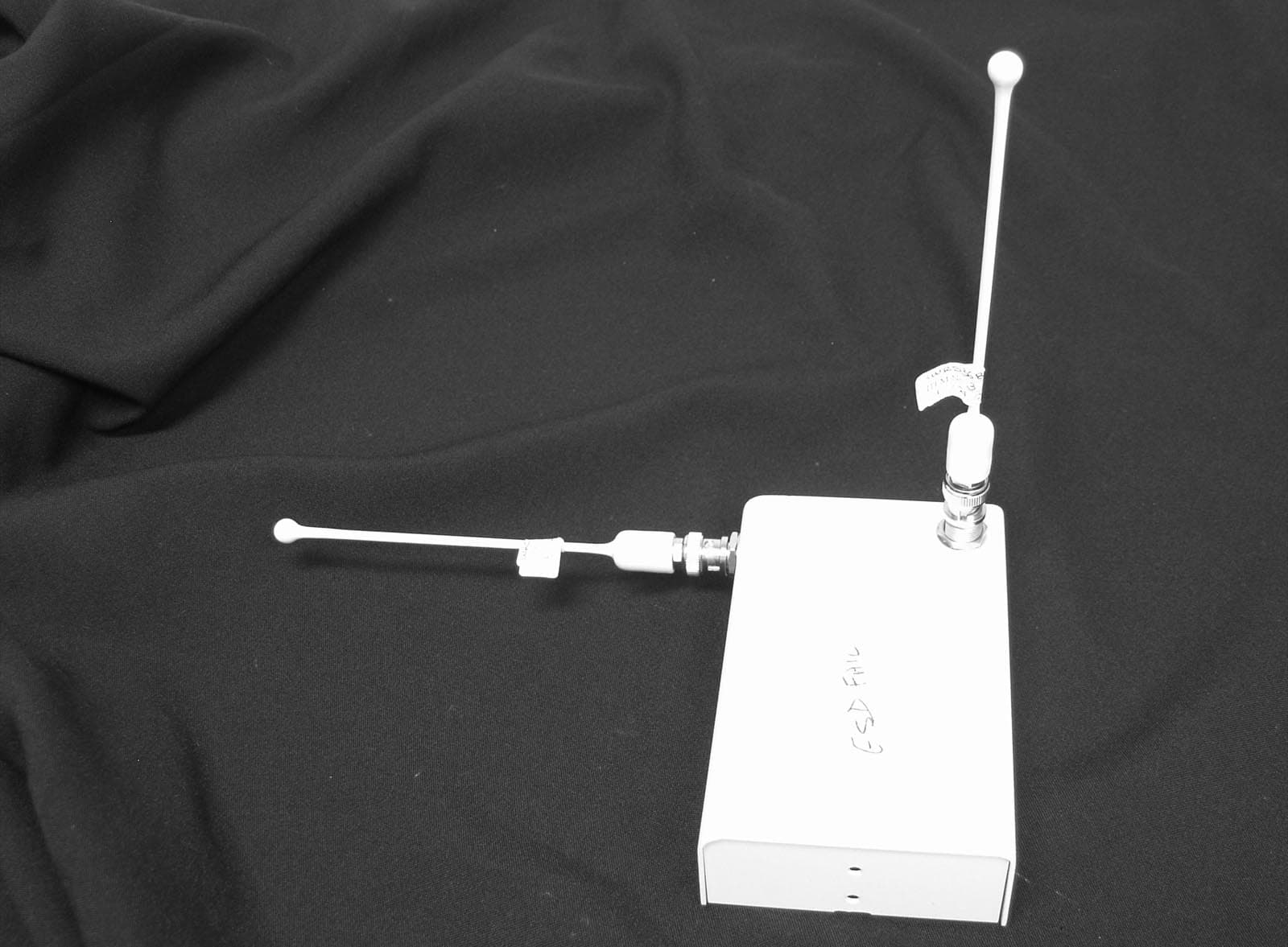
Click to zoom
Application Details
- Equipment Class
- CYY - Communications Receiver used w/Pt 15 Transmitter
- Date of Grant
- Mar 14, 2005
- Application Purpose
- Original Equipment
- Date of Application
- Mar 14, 2005
- Equipment Note
- International LAR 806A5301
- Frequency Range
- 433.42000000 - 434.42000000
- Company
- Xmark Corporation
- Country
- Canada
Documents & Files
Document Text
Text extracted from the exhibit documents filed with the FCC. Open a document above to read the original.
Users Manual
Materials Required• Local Area Receiver (p/n 806A5301); includes antennas, Caddy clip and mounting hardware. • Facility fl oor plan indicating LAR position and network wiring path. • 105 Ω network terminator (p/n 805A2401) required to terminate network. Two provided with each Controller (p/n 805A2201). Important Reference Documents• Hugs Installation Manual (p/n 805I0301)• MyCall/FindIt Installation Manual (p/n 805I0401) Materials RequiredImportant Reference Documents Have you: • Pulled network and power cable?• Resolved power supply requirements?• Selected the location for the LAR? LAR Orientation • Main antenna should be pointing downward into an area free of metal obstructions. • Ensure that the LAR is at least 2 ft. (60 cm) from metal objects, such as framing or air ducts. Specifi cations WarrantyXmark’s products are warranted against defects in materials and workmanship and shall perform in accordance with published speci-fi cations for a period of one year. Instantel Inc. reserves the right to change specifi cations without notice. Limitation of LiabilityThis Product has been designed for use to assist personnel in sum-moning help when they are under personal duress and/or locate assets.The range, accuracy, function and performance of this Product may vary from the published specifi cations due to many factors, including, without limitation, site impairments from structural effects, metal objects in the vicinity, placement of the receiver and transmitter, interference from other electrical devices, atmospheric effects, installation, and maintenance. There may be other factors, which also affect performance of this Product. Instantel does not guarantee that this Product will detect 100% of the calls for personal assistance and locate all assets 100% of the time. Instantel does not guarantee that this Product will not return false reports of calls for personal assistance and/or location of assets. Monthly testing and maintenance of this Product, as described in the Product documentation, is essential to verify the system is operating correctly and to ensure that the probability of detecting an alarm and/or locating the transmitter are maximized. The failure to undertake regular testing and maintenance will increase the risk of system failure and failure to report personal duress calls and/or failure to locate assets. The failure to undertake regular test-ing and maintenance will increase the risk of false reports of calls for personal assistance and/or location of assets.Instantel hereby disclaims all warranties, express or implied, arising out of or in connection with any of its Products of the use or perfor-mance thereof, including but not limited to, where allowable by law, all other implied warranties or conditions of merchantable quality and fi tness for a particular purpose and those arising by statute or otherwise in law or from a course of dealing or usage of trade.Instantel’s liability to you or anyone claiming through or on behalf of you with respect to any claim or loss arising out of the use or misuse of Instantel’s Product, defective products or materials, improper installation or maintenance of Instantel’s Product or products or the system in which they are incorporated, or alleged to have resulted from an act or omission of Instantel or any person, negligent or otherwise, shall be limited to:A) The repair or replacement of defective Product or materials sup- plied by Instantel during the warranty period as set out in the Product documentation; or, at the option of Instantel, B) Refund of the purchase price of the Product supplied by Instan- tel. In no event shall Instantel be liable for general, specifi c, indirect, consequential, incidental, exemplary or punitive damages or any losses or expenses suffered by you or anyone else, whether or not Instantel, or its employees, offi cers, agents, resellers or installers has been informed of the risk of such loss or expense and whether or not such losses or expenses were foreseeable.StatementsUnited States—Federal Communication Commission (FCC)This device complies with Part 15 of the FCC Rules. Operation is subject to the following two conditions: (1) this device may not cause harmful interference, and (2) this device must accept any interference received, including interference that may cause unde-sired operation.NOTE: This equipment has been tested and found to comply with the limits for a Class A digital device, pursuant to Part 15 of the FCC Rules. These limits are designed to provide reasonable protection against harmful interference when the equipment is operated in a commercial environment. This equipment generates, uses, and can radiate radio frequency energy and, if not installed and used in accor-dance with the instruction manual, may cause harmful interference to radio communications. Operation of this equipment in a residential area is likely to cause harmful interference in which case the user will be required to correct the interference at his own expense. Warning : Changes or modifi cations not expressly approved by Xmark could void the user’s authority to operate the equipment.Canada—Industry CanadaThe term “IC:” before the certifi cation/registration number only signifi es that Industry Canada technical specifi cations were met. European Union—CE declarationXmark hereby declares that this radio frequency receiver is in compli-ance with the essential requirements and other relevant provisions of Directive 1999/5/EC. Service LightThe service light is located beside the secondary antenna, and indi-cates the current status of the LAR, as shown in the table below. Part Number 806A5301 Local Area Receiver Guide © 2005 Xmark, a division of Instantel Inc. All Rights Reserved. FindIt, MyCall and Hugs are registered trademarks of Instantel Inc. in North America. Xmark and the Xmark logo are trademarks of Instantel Inc. All other company and product names may be trademarks of their respective compa- nies. Printed in Can…
Text truncated - open the document above for the full version.
ID Label/Location Info
21 54 11 82 72 41 63 10 3 1. SEE SHEET 2 FOR PACKAGING INSTRUCTIONS2. FASTEN ONLY THE LARGE SECTION OF LABEL ITEM 12 TO BOTTOM OF CASE AND PLACE THE 2 REMAINING SMALLER LABELS IN PLASTIC BAG WITH THE OTHER HARDWARE3. INSURE PCB IS RESTING ON MOUNTING STANDOFFS BEFORE TIGHTENING CONNECTOR HARDWARE TO PREVENT STRESS ON PCB.NOTES: 12 1 13 1 14 1 SEE NOTE 2 31 DO NOT INSTALL GASKETSUPPLIED WITH CONNECTOR. SEE NOTE 3 26 1 POSITION SHIELD WITHNOTCH OVER JP5 8 REF 7 REF 28 1 APPLY 748 SILICONE TO AJUSTMENT SCREW OFL13 AFTER FINAL TEST 13 REF 12 REF (FCC INFO) (NEURON ID INFO) INSPECTION STAMP LOCATION 28 REF .12 APPROX. .25APPROX 14 REF (INSTALL INFO.) 1 A 23 B C E D 123 45 67 A B C MANUFACTURE OR ANY OTHER PURPOSE WITHOUTPRIOR WRITTEN CONSENTFROM INSTANTEL INC. REV INFORMATION CONTAINEDON THIS DRAWING IS THEPROPERTY OF INSTANTELINC. AND SHALL NOT BEREPRODUCED FOR DRAWN BY DWG NO. ECO# DATE DATE INC DESIGNED BY PRODUCT TITLE SHEET of 45 D E 67 INTERNATIONAL LAR UNIT ASSY 806A5301 M.ILIEVA 26-11-04 PERCEPTIS L. MANSON 12 A 31317 14-DEC-01 MI
Test Report
Master: PT15209 Date: December 12, 2001 Test Report: 5W36823.8 Issue 3 Applicant: Instantel Inc. 309 Legget Drive Kanata, Ontario K2K 3A3 Equipment Under Test: International Local Area Receiver (EUT) FCC ID: ISEILR In Accordance With: FCC Part 15, Subpart B, 15.107 and 15.109 Tested By: Nemko Canada Inc. 303 River Road, R.R. 5 Ottawa, Ontario K1V 1H2 Authorized By: Sim Jagpal, Resource Manager Date: March 29, 2005 Total Number of Pages: 12 Nemko Canada Inc. FCC PART 15, SUBPART B, 15.107 and 15.109 PROJECT NO.: 5W36823.8 Issue 3 EQUIPMENT: International Local Area Receiver Page 2 of 12 Table Of Contents Section 1. Summary Of Test Results ..................................................................................3 Section 2. General Equipment Specification......................................................................5 Section 3. Powerline Conducted Emissions........................................................................6 Section 4. Radiated Emissions .............................................................................................9 Section 5. Block Diagrams .................................................................................................11 Section 6. Test Equipment List .........................................................................................12 Nemko Canada Inc. FCC PART 15, SUBPART B, 15.107 and 15.109 PROJECT NO.: 5W36823.8 Issue 3 EQUIPMENT: International Local Area Receiver Page 3 of 12 Section 1. Summary Of Test Results General All measurements are traceable to national standards. These tests were conducted on a sample of the equipment for the purpose of demonstrating compliance with FCC Part 15, Subpart B for digital emissions. All tests were conducted using measurement procedure ANSI C63.4-2003. Radiated Emissions were made on an open area test site. A description of the test facility in on file with the FCC. THIS TEST REPORT RELATES ONLY TO THE ITEM(S) TESTED. THE FOLLOWING DEVIATIONS FROM, ADDITIONS TO, OR EXCLUSIONS FROM THE TEST SPECIFICATIONS HAVE BEEN MADE. See “ Summary of Test Data”. March 29, 2005 TESTED BY: _______________________________ DATE: ___________________ Jason Nixon, Telecom Specialist Nemko Canada Inc. authorizes the above named company to reproduce this report provided it is reproduced in its entirety and for use by the company’s employees only. Any use which a third party makes of this report, or any reliance on or decisions to be made based on it, are the responsibility of such third parties. Nemko Canada Inc. accepts no responsibility for damages, if any, suffered by any third party as a result of decisions made or actions based on this report. This report applies only to the items tested. Nemko Canada Inc. FCC PART 15, SUBPART B, 15.107 and 15.109 PROJECT NO.: 5W36823.8 Issue 3 EQUIPMENT: International Local Area Receiver Page 4 of 12 Summary Of Test Data Name Of Test Para. No. Result Powerline Conducted Emissions 15.107 Complies Radiated Emissions 15.109 Complies Footnotes For N/A’s: None Test Conditions: Indoor Temperature: 23°C Humidity: 16% Outdoor Temperature: 10°C Humidity: 43% Nemko Canada Inc. FCC PART 15, SUBPART B, 15.107 and 15.109 PROJECT NO.: 5W36823.8 Issue 3 EQUIPMENT: International Local Area Receiver Page 5 of 12 Section 2. General Equipment Specification Manufacturer: Instantel Inc. Model No.: 806A5301 Serial No.: None Date Received In Laboratory: January 21, 2005 Nemko Identification No.: 7 Receive Frequency Range: 433.42-434.42MHz (Direct Conversion) Power Source: 10 to 30 VDC Nemko Canada Inc. FCC PART 15, SUBPART B, 15.107 and 15.109 PROJECT NO.: 5W36823.8 Issue 3 EQUIPMENT: International Local Area Receiver Page 6 of 12 Section 3. Powerline Conducted Emissions Para. No.: 15.107 Test Performed By: Jason Nixon Date of Test: January 24, 2005 Minimum Standard: Frequency Maximum Powerline Conducted RF Voltage (dBμV) (MHz) Quasi-peak Average 0.15 – 0.5 66 to 56 56 to 46 0.5 – 5 56 46 5 – 30 60 50 Test Results: Complies These test results were achieved using a representative 12VDC power supply (M/N: DV-1250) Measurement Data: See attached graphs and tabulated data. Emissions in the graphs are measured using a Peak detector and compared to the Average limit. Any emission found to be above the limit using the Peak detector was remeasured using an Average and Quasi-peak detector and recorded in the Table below. Conductor Frequency (MHz) Detector Emission Level (dBuV) LISN Loss (dB) Cable Loss (dB) Result (dBuV) Limit (dBuV) Margin (dB) Quasi Peak37.6 0.00 0.11 37.71 56.0 18.3 1 Phase 0.5439 Average 9.6 0.00 0.11 9.71 46.0 36.3 Quasi Peak34.2 0.00 0.15 34.35 56.0 21.6 2 Neutral 0.5230 Average 7.1 0.00 0.15 7.25 46.0 38.7 Nemko Canada Inc. FCC PART 15, SUBPART B, 15.107 and 15.109 PROJECT NO.: 5W36823.8 Issue 3 EQUIPMENT: International Local Area Receiver Page 7 of 12 Nemko Canada Inc. FCC PART 15, SUBPART B, 15.107 and 15.109 PROJECT NO.: 5W36823.8 Issue 3 EQUIPMENT: International Local Area Receiver Page 8 of 12 Nemko Canada Inc. FCC PART 15, SUBPART B, 15.107 and 15.109 PROJECT NO.: 5W36823.8 Issue 3 EQUIPMENT: International Local Area Receiver Page 9 of 12 Section 4. Radiated Emissions Para. No.: 15.109 Test Performed By: Jason Nixon Date of Test: January 26, 2005 Minimum Standard: Fundamental (MHz) Field Strength (μV/m) Field Strength (dBμV) 0.009 - 0.490 2400/F(kHz) @ 300m — 0.490 - 1.705 24000/F(kHz) @ 30m — 1.705 - 30 30 @ 30m — 30 - 88 100 40.0 88 - 216 150 43.5 216 - 960 200 46.0 Above 960 500 54.0 Test Results: Complies Measurement Data: See attached table. All measurements were performed using a Peak Detector with 100kHz RBW below 1GHz and a 1MHz RBW above 1GHz. All emissions were searched from 30MHz up to the 10 th harmonic of the receiver. Nemko Canada Inc. FCC PART 15, SUBPART B, 15.107 and 15.109 PROJECT NO.: 5W36823.8 Issue 3 EQUIPMENT: International Local Area Receiver Page 10 of 12 Frequency (MHz) Antenna Polarit y RCVD Signal (dBuV) Ant. Factor (dB) Cable Los…
Text truncated - open the document above for the full version.
Contact Information
Applicant
Peter Rousseau(RF Technologist)
Technical Contact
Instantel Inc.Chris Bisaillion
[email protected]613-592-4642
309 Legget Drive · Kanata, Ontario · Canada
Test Firm
Nemko Canada Inc. (Ottawa)Charles Neal
Technical Specifications
| # | Rule Parts | Frequency Range | Power Output |
|---|---|---|---|
| 1 | 15B | 433.42 MHz - 434.42 MHz | - |
Other Applications from Xmark Corporation
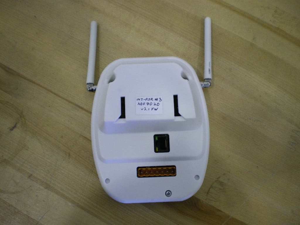
ISEIPSR
Dec 02, 2010434MHz International Patient Security Receiver
Equipment Class
CYY - Communications Receiver used w/Pt 15 Transmitter
ISEXCR
Oct 16, 2007Transceiver Exciter
Equipment Class
DCD - Part 15 Low Power Transmitter Below 1705 kHz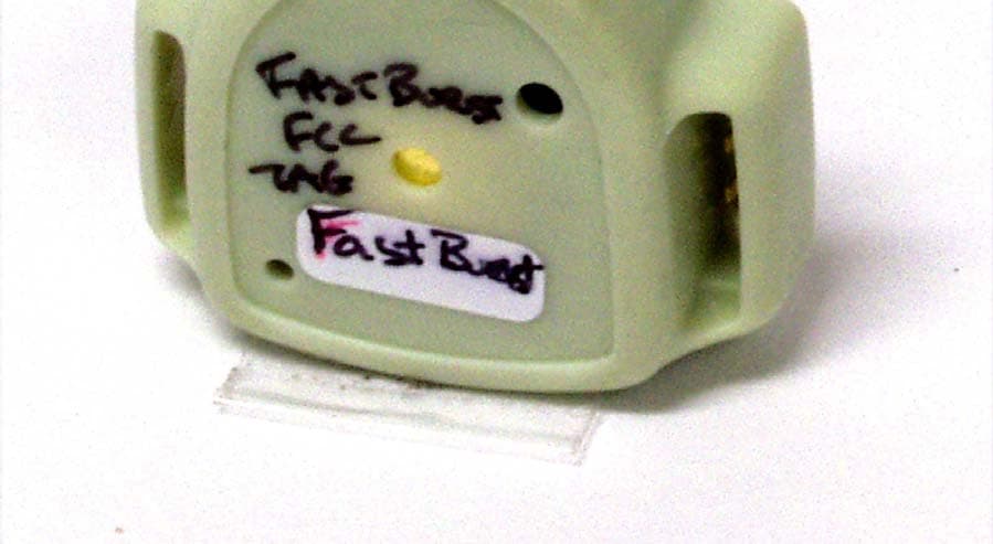
ISEH2H
Jun 20, 2006Infant Tag
Equipment Class
DSR - Part 15 Remote Control/Security Device Transceiver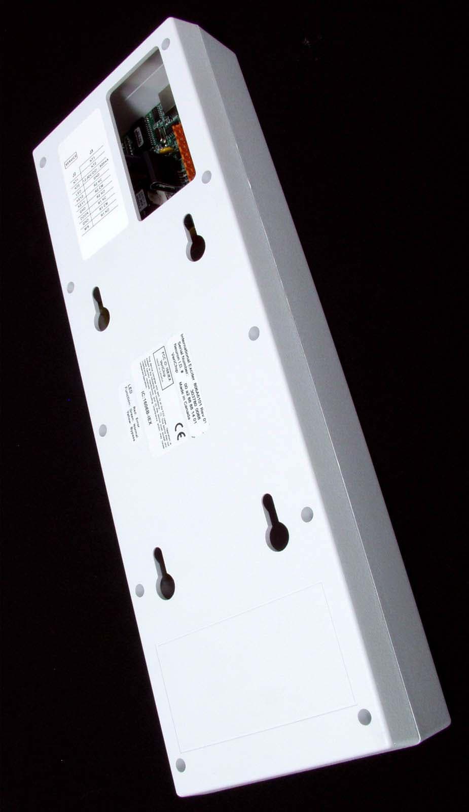
ISEIEX
Aug 25, 2005Low Power Transmitter
Equipment Class
DCD - Part 15 Low Power Transmitter Below 1705 kHz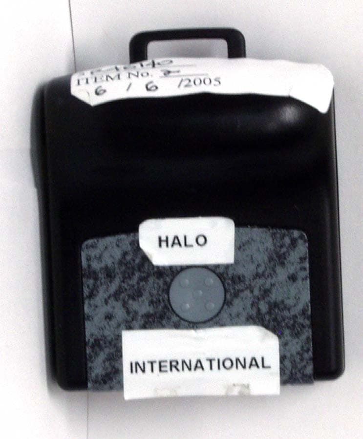
ISEIMF
Jun 23, 2005Communicator Tag
Equipment Class
DSC - Part 15 Security/Remote Control Transmitter