ISEXCRTransceiver Exciter
Xmark Corporation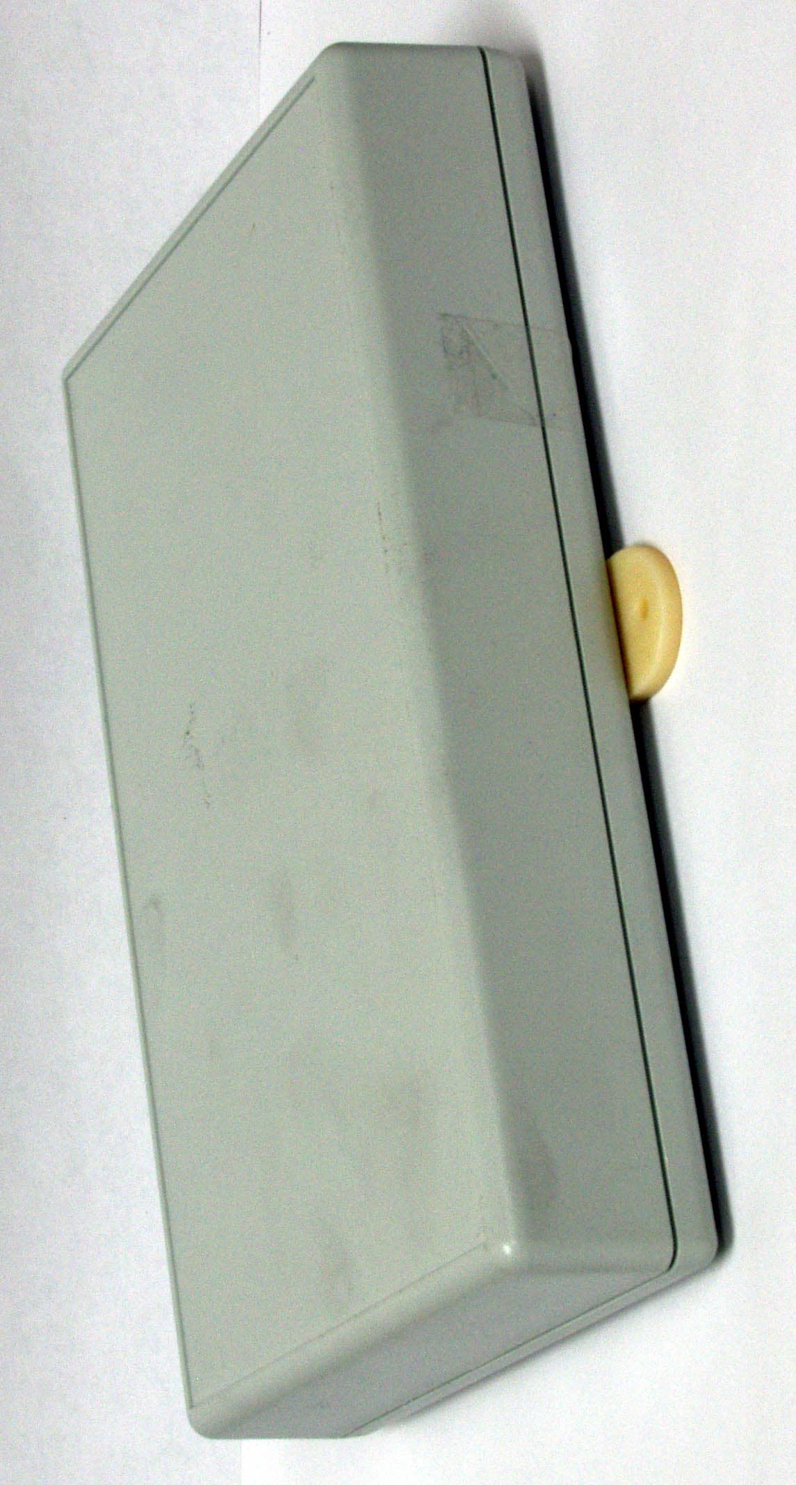
Click to zoom
Application Details
- Equipment Class
- DCD - Part 15 Low Power Transmitter Below 1705 kHz
- Date of Grant
- Oct 16, 2007
- Application Purpose
- Original Equipment
- Date of Application
- Oct 16, 2007
- Equipment Note
- Transceiver Exciter
- Frequency Range
- 0.30720000 - 0.30720000
- Company
- Xmark Corporation
- Country
- Canada
Documents & Files
Document Text
Text extracted from the exhibit documents filed with the FCC. Open a document above to read the original.
Users Manual
Tran scei ver Exciter Installation Manual Warranty Xmark's products are warranted against defects in materials and workmanship and shall perform in accordance with published specifications for 1 year. Xmark's warranty is limited solely to the repair or replacement of the defective part or product. Xmark reserves the right to change product specifications without notice. Regulatory Statements United States - Federal Communication Commission (FCC) This device complies with Part 15 of the FCC Rules. Operation is subject to the following two conditions: (1) this device may not cause harmful interference, and (2) this device must accept any interference received, including interference that may cause undesired operation. NOTE: This equipment has been tested and found to comply with the limits for a Class A digital device, pursuant to Part 15 of the FCC Rules. These limits are designed to provide reasonable protection against harmful interference when the equipment is operated in a commercial environment. This equipment generates, uses and can radiate radio frequency energy and, if not installed and used in accordance with the instruction manual, may cause harmful interference to radio communications. Operation of this equipment in a residential area is likely to cause harmful interference in which case the user will be required to correct the interference at his own expense. Warning: Any changes or modifications not expressly approved by Xmark could void the user's authority to operate the equipment. Canada - Industry Canada The term "IC:" before the certification/registration number only signifies that Industry Canada technical specifications were met. Important Recommendation Xmark’s systems are designed to assist staff in providing a high degree of safety for people and assets and therefore should be used as a component of a comprehensive security program of policies, procedures, and processes. As with every security system, Xmark highly recommends regular system operational checks to verify functional integrity. 1 Transceiver Exciter Installation Guide Introduction The exciter is an additional Low Frequency (LF) antenna for a Transceiver. By using exciters, additional LF Fields can be created and the tag detection zones can be extended. Each Transceiver supports a maximum of three transceiver exciters. The LF Fields of the Transceiver and all exciters will be in phase. Figure 1: Exciter Front Panel The exciter is connected to a transceiver (Part Number SR4TX01) from the exciter’s XCVR PORT to any one of the transceiver’s three SATELLITE EXCITERS ports using a standard ethernet cable (CAT5, EIA 568A termina- tion). The exciter also draws its power from this connection. Firmware Updates The exciter does not contain firmware. Its operating features are dependent on the Transceiver. Installation Tips When installing the exciter: • Use both mounting holes to ensure that the exciter is secure. • Mount the exciter so that the front panel is easily accessible and visible from the floor. If mounting above a ceiling, place the exciter so that the front panel is visible from the floor when a ceiling tile is removed. • Check that the LF Field radiated by the exciter(s) and the Transceiver is continuous (no dead spots) and that it covers the correct area. See “Configuration” on page 4. Location Selection Any of the following are suitable locations for an exciter: 2 Transceiver Exciter Installation Guide • On the wall above the egress point or monitored area. •Inside a wall cavity. • On the sidewall along the hallway mounted flat against the wall. Location Considerations When planning the exciter location, consider the following: •Ceiling Height and Corridor Width — The exciter LF Field should extend to the floor and from one wall of the corridor to the other. Tags must not be able to pass under or around the LF Field. •Any Nearby Metal — Large metal surfaces close to the exciter can distort the LF Field in unpredictable ways. This effect can increase or decrease the LF Field strength and even extend the LF Field shape. At times this effect can be used to advantage but the desired result can only be obtained experimentally. Metal plate, foil, or mesh must not come between the exciter and the tags to be queried and read. The exciter top, bottom, and rear panels must be at least 3 in. (7.6 cm) from any metallic surfaces. •LF Field Shape — In the absence of large metal objects the LF Field is a sphere with a 15 ft. (4.5 m) maximum radius centered around the exciter. As a result, the LF Field range is unaffected by rotating the exciter, or by placing the exciter verti- cally or horizontally. •Adjacent Floors — If the LF Field extends into adjacent floors, it will cause tags on the adjacent floors to be reported as if on the exciter floor. LF Field Coverage When the exciter is used to monitor an egress point, such as a door or elevator, the LF Field(s) should cover all possible approaches. As many as three exciters can be used with a single Transceiver to modify the LF Field for this application. Tags must be detected at least 8 ft. (2.4 m) before the door when the Transceiver is part of a door locking system. This ensures adequate time for the lock to ener- gize before the tag reaches the doorway. The LF Field should not extend into adjacent areas, including adjacent floors, containing tags. These tags could cause the Transceiver to activate the lock even though tags are not approaching the exit. Exciter Installation To install the exciter: 1 Mount the exciter with #8 hardware using the two mounting holes. 2 Record the exciter location for later consideration. 3 Route the cable (not supplied) from the exciter to the Transceiver. 3 Transceiver Exciter Installation Guide 4 Disconnect the Transceiver from its power supply. 5 Plug the cable into the Transceiver and the exciter. 6 Reconnect the Transceiver power supply. 7 Verify that the exciter power LED and the field intensity LED are on. See Figure 1 for the…
Text truncated - open the document above for the full version.
ID Label/Location Info
AFFIX FCC ID LABEL P/N 510-000170-000CENTER ON BACK OF UNIT AS SHOWN. TOP OF LABEL TRANSCEIVER EXCITER P/N 600-000302-000 ASSEMBLY 1 AB 2 C D E 12 34567 A B PRODUCT DESIGNED BYDRAWN BYDATE FROM VERICHIP CORP.PRIOR WRITTEN CONSENTOTHER PURPOSE WITHOUTMANUFACTURE OR ANY REPRODUCED FOR CORP. AND SHALL NOT BE PROPERTY OF VERICHIPON THIS DRAWING IS THEINFORMATION CONTAINED ECO# REV DATE INC DWG NO.TITLE SHEET of 345 C D 67 E 1 ENGINEER L. MANSON 26-09-07 ROAM & HALO TRANSCEIVER EXCITER 600-000302-000 1 2 33250 26-09-07 LM
Test Report
www.nemko.com FCC Part 15 Subpart B, June 2006 Test Report: 89967-1TRFWL Applicant: Xmark Corporation 309 Legget Drive Kanata, Ontario K2K 3A3 Apparatus: Exciter (M/N: 600-000302-000) FCC ID: ISEXCR In Accordance With: FCC Part 15 Subpart C, 15.207 and 15.209 Intentional Radiators Tested By: Nemko Canada Inc. 303 River Road Ottawa, Ontario K1V 1H2 Authorized By: Roman Kuleba, Wireless Specialist Date: September 19, 2007 Total Number of Pages: 21 Nemko Canada Inc. REPORT SUMMARY Report Number: 89967-1TRFWL FCC ID: ISEXCR Specification: FCC Part 15 Subpart C Page 2 of 21 Report Summary These tests were conducted on a sample of the equipment for the purpose of demonstrating compliance with Part 15, Subpart C. Radiated tests were conducted in accordance with ANSI C63.4-2003. Radiated emissions are made on an open area test site. A description of the test facility is on file with the FCC. The assessment summary is as follows: Apparatus Assessed: Exciter (M/N: 600-000302-000) Specification: FCC Part 15 Subpart C, 15.207 and 15.209 Compliance Status: Complies Exclusions: None Non-compliances: None Report Release History: Original Release Author: Jason Nixon, Telecom Specialist Note that the results contained in this report relate only to the items tested and were obtained in the period between the date of initial receipt of samples and the date of issue of the report. This test report has been completed in accordance with the requirements of ISO/IEC 17025. Nemko Canada Inc. authorizes the applicant to reproduce this report provided it is reproduced in its entirety and for use by the company’s employees only. Any use which a third party makes of this report, or any reliance on or decisions to be made based on it, are the responsibility of such third parties. Nemko Canada Inc. accepts no responsibility for damages, if any, suffered by any third party as a result of decisions made or actions based on this report. Nemko Canada Inc. REPORT SUMMARY Report Number: 89967-1TRFWL FCC ID: ISEXCR Specification: FCC Part 15 Subpart C Page 3 of 21 TABLE OF CONTENTS Report Summary......................................................................................................................................... 2 Section 1 : Equipment Under Test............................................................................................................. 4 1.1 Product Identification .................................................................................................................................4 1.2 Samples Submitted for Assessment............................................................................................................4 1.3 Theory of Operation ...................................................................................................................................4 1.4 Technical Specifications of the EUT ..........................................................................................................5 1.5 Block Diagram of the EUT.........................................................................................................................5 Section 2 : Test Conditions......................................................................................................................... 6 2.1 Specifications .............................................................................................................................................6 2.2 Deviations From Laboratory Test Procedures ............................................................................................6 2.3 Test Environment .......................................................................................................................................6 2.4 Test Equipment...........................................................................................................................................6 2.5 Measurement Uncertainty...........................................................................................................................6 Section 3 : Observations ............................................................................................................................. 7 3.1 Modifications Performed During Assessment ............................................................................................7 3.2 Record Of Technical Judgements ...............................................................................................................7 3.3 EUT Parameters Affecting Compliance .....................................................................................................7 3.4 Test Deleted................................................................................................................................................7 3.5 Additional Observations .............................................................................................................................7 Section 4 : Results Summary ..................................................................................................................... 8 4.1 FCC Part 15 Subpart C : Test Results ........................................................................................................9 Appendix A : Test Results ........................................................................................................................ 10 Clause 15.207(a) Conducted Emissions ..............................................................................................................10 Clause 15.209(a) Radiated Emissions, General Limits........................................................................................14 Clause 15.215(c) 20dB Bandwidth ......................................................................................................................18 Appendix B : Setup Photographs ............................................................................................................ 19 Appe…
Text truncated - open the document above for the full version.
Contact Information
Applicant
Peter Rousseau(RF Technologist)
Technical Contact
Test Firm
Nemko Canada Inc. (Ottawa)Charles Neal
Technical Specifications
| # | Rule Parts | Frequency Range | Power Output |
|---|---|---|---|
| 1 | 15C | 0.3072 MHz - 0.3072 MHz | - |
Other Applications from Xmark Corporation
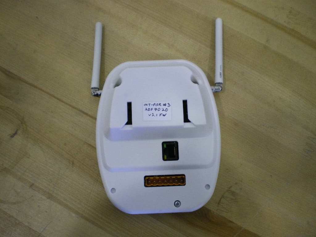
ISEIPSR
Dec 02, 2010434MHz International Patient Security Receiver
Equipment Class
CYY - Communications Receiver used w/Pt 15 Transmitter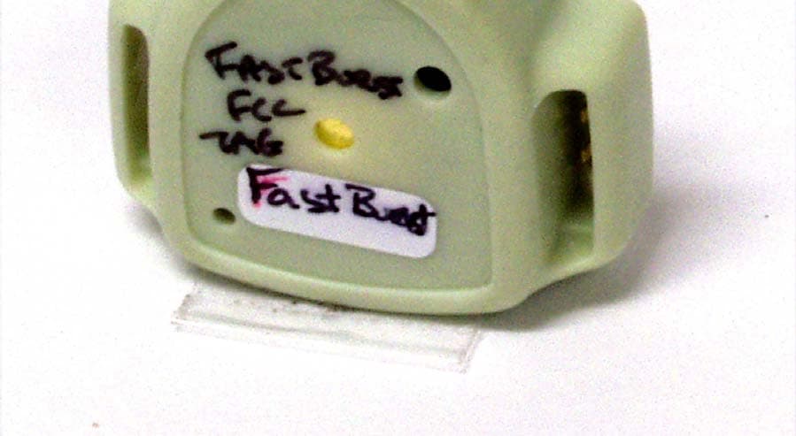
ISEH2H
Jun 20, 2006Infant Tag
Equipment Class
DSR - Part 15 Remote Control/Security Device Transceiver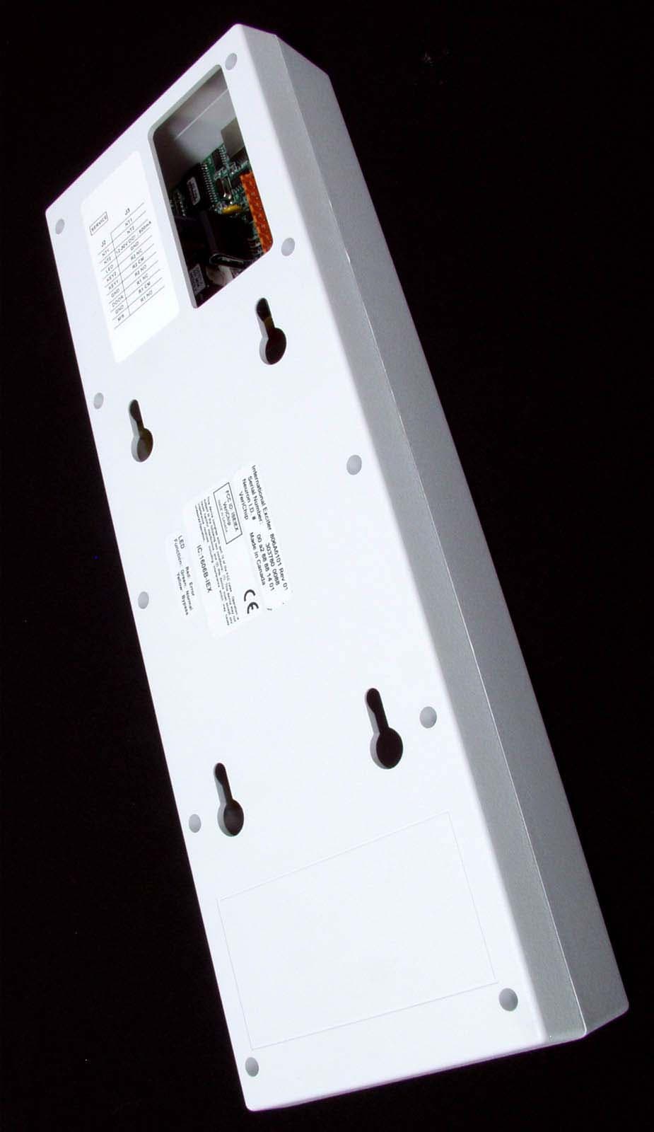
ISEIEX
Aug 25, 2005Low Power Transmitter
Equipment Class
DCD - Part 15 Low Power Transmitter Below 1705 kHz
ISEIMF
Jun 23, 2005Communicator Tag
Equipment Class
DSC - Part 15 Security/Remote Control Transmitter
ISEITG
Mar 14, 2005International Hugs Tag 806A5201
Equipment Class
DSR - Part 15 Remote Control/Security Device Transceiver