ISEIMFCommunicator Tag
Xmark Corporation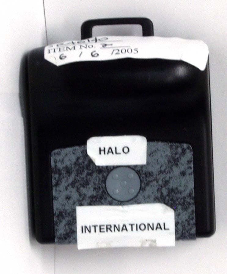
Click to zoom
Application Details
- Equipment Class
- DSC - Part 15 Security/Remote Control Transmitter
- Date of Grant
- Jun 23, 2005
- Application Purpose
- Original Equipment
- Date of Application
- Jun 23, 2005
- Equipment Note
- Communicator Tag
- Frequency Range
- 433.42000000 - 434.42000000
- Company
- Xmark Corporation
- Country
- Canada
Documents & Files
Document Text
Text extracted from the exhibit documents filed with the FCC. Open a document above to read the original.
Users Manual
Part Number 806A5601 MyCall Communicator Tag Guide Materials Required• MyCall ® Communicator ™ tag (p/n 806A5601)—includes bat- tery (installed). • MyCall Communicator tag fasteners. One of the following is required:• Neck chain or cord to wear around the neck.• Strap clips to clip Communicator tags to clothing.• Emergency Release Clip Set (p/n 805A3001) to fasten Com- municator tags with a breakaway Panic alarm feature. Set includes 12 Release Clips (12 Alarm Clips and 12 Alarm Keys). Use Considerations• Wear the Communicator tag in full view. The tag must remain visible in order to receive Beacon location transmissions. Do not cover the front of the tag when wearing it, or place it in a shirt or pants pocket. • Point the bulge outward to maximize the reception of Beacon location marker transmissions. • Do not place the Communicator tag where it could be bumped or damaged. • If using the Emergency Release Clip, ensure the breakaway chain or cords do not break before pulling the Alarm Key out of the Alarm Clip. • Do not mix FindIt ® tags with MyCall Communicator tags. FindIt tags are designed specifi cally for the FindIt asset locating application. MyCall Communicator tags are designed specifi cally for the MyCall emergency response application. The Panic Alarm FeatureTo call for help at any time, simply press the top or bottom button on the Communicator tag. As an option, the tag can be confi gured to emit a series of short beeps each time it is pressed. Installing the TagCommunicator tags can be worn in three different ways: around the neck like a pendant, clipped to a person’s clothes, or fastened securely to a person’s clothes to cause a Panic alarm automatically if pulled off.1 Turn the Communicator tag on. The MyCall Communicator tag ships from the factory in a “sleep” mode to minimize battery consumption. Press either Communicator tag button to turn the Communicator tag on. The Communicator tag emits a short beep. 2 Test the Communicator tag. Before installing the Communicator tag, check that it is operating properly. Turn on Tag Diagnostics in the Xmark ® software, and then initiate a Panic alarm. Check the Xmark software to make sure that the alarm message has been received. 3 Fasten the Communicator tag. Installation differs depending upon the fastener used.A Fastened to a neck chain or cord Slip the neck chain or cord through the loop located on the top of the Communicator tag. Use a standard or breakaway chain or cord, as required. Materials RequiredUse ConsiderationsThe Panic Alarm Feature Wearing the Communicator Tag © 2005 Xmark, a division of Instantel Inc. All Rights Reserved. Xmark, the Xmark logo, MyCall and FindIt are registered trademarks of Instantel Inc. in North America. Communicator is a trademark of Instantel Inc. All other company and product names may be trademarks of their respective companies. Printed in Canada. June 2005. 806U5401 Rev 01. 808 Commerce Park Drive, Ogdensburg, NY 13669 USA or 309 Legget Drive, Ottawa, ON K2K 3A3, Canada Telephone: 1-866-55-XMARK International: +1 613-592-6997 Facsimile: 1-613-592-4296 E-mail: [email protected] Web Site: www.xmarksystems.com Certifi ed to the ISO 9001 Quality Standard B Fastened to a strap clip Slip the strap clip through the loop located on the top of the Communicator tag and clip onto the person’s clothing. C Fastened using the Emergency Release Clip (p/n 805A3001), which consists of the Alarm Clip and Alarm Key. The Emer-gency Release Clip provides a breakaway alarm feature. 1 Insert the Alarm Key into the Alarm Clip. Position the Key so that the hammer on the Clip sits in the Key’s small slot. The large loop on the Key should be at the bottom. 2 Remove the screw located on the back of the MyCall Communicator tag. 3 Remove the backing from the adhesive tape on the back of the Alarm Clip, and attach the Clip to the Communi-cator tag, with the round end pointing towards the loop on the top of the Communicator tag. Make sure to align the screw hole in the Alarm Clip with the screw hole on the Communicator tag. 4 Insert the screw and secure being careful not to over- tighten and risk damaging the Communicator tag. Warning : Do not apply Locktite or other adhesives to the Communicator tag or screw. 5 Slip a chain or cord through the Alarm Key’s larger loop. Fasten the other end securely to the person. Slip a break-away neck chain or cord through the Communicator tag’s loop and place around the person’s neck. 6 Test the arrangement. Pull on the Communicator tag. The Alarm Key should separate from the Alarm Clip and cause a Panic alarm. The chain or cords used must not break before this occurs. Final StepsOnce the Communicator tag is attached, it must be enrolled in the Xmark software. Refer to the MyCall/FindIt System Manual for detailed information on how to complete these steps.Monthly TestingTest the Communicator tag monthly by pressing the top and bottom buttons, separately and at the same time, to cause a Panic alarm. Check the Xmark software to ensure the Panic alarm was received in each case.Replacing the BatteryThe Controller PC monitors the battery level of all Communicator tags, and displays a Low Battery alarm when the battery needs to be replaced. Use only these recommended battery types: Tadiran 3.6 VDC model TL-2150/S) or Saft 3.6 VDC (model LS14250). Other battery types may fail to perform or leak and cause damage to the device, voiding the warranty. Do not use 7.6 VDC ½ AA lithium batteries. Electrostatic discharge could damage the Communicator tag when changing the battery—touch your hand to ground to discharge any electrostatic charge before handling the components. Dispose of batteries according to local legislative requirements. Do not recharge, force open, heat, or dispose of in fi re. This may lead to explosion or leakage, causing personal injury. Handling InformationCleaning : The tag my be wiped with a dry cloth. Do not wash, expose to high pressure water, autoclave, or otherwise imme…
Text truncated - open the document above for the full version.
Test Report
FCC Part 15 Subpart C, 15.231 : February 2005 Test Report: 5W46140.3 Applicant: Instantel Inc. 309 Legget Drive, Kanata, ON K2K 3A3 Apparatus: International MyCall Tag FCC ID: ISEIMF In Accordance With: FCC Part 15 Subpart C, 15.231 Periodic operation in the band 40.66-40.70MHz and above 70 MHz. Tested By: Nemko Canada Inc. 303 River Road Ottawa, Ontario K1V 1H2 Authorized By: Sim Jagpal, Resource Manager Date: 22 June 2005 Total Number of Pages: 19 Nemko Canada Inc. REPORT SUMMARY Report Number: 5W46140.3 FCC ID: ISEIMF Specification: FCC Part 15 Subpart C, 15.231 Page 2 of 19 Report Summary These tests were conducted on a sample of the equipment for the purpose of demonstrating compliance with Part 15, Subpart C. Radiated tests were conducted is accordance with ANSI C63.4-2003. Radiated emissions are made on an open area test site. A description of the test facility is on file with the FCC. The assessment summary is as follows: Apparatus Assessed: International MyCall Tag Specification: FCC Part 15 Subpart C, 15.231 Compliance Status: Complies Exclusions: None Non-compliances: None Report Release History: Original Release Author: Jason Nixon, Telecom Specialist Note that the results contained in this report relate only to the items tested and were obtained in the period between the date of initial receipt of samples and the date of issue of the report. This test report has been completed in accordance with the requirements of ISO/IEC 17025. Nemko Canada Inc. authorizes the applicant to reproduce this report provided it is reproduced in its entirety and for use by the company’s employees only. Any use which a third party makes of this report, or any reliance on or decisions to be made based on it, are the responsibility of such third parties. Nemko Canada Inc. accepts no responsibility for damages, if any, suffered by any third party as a result of decisions made or actions based on this report. Nemko Canada Inc. REPORT SUMMARY Report Number: 5W46140.3 FCC ID: ISEIMF Specification: FCC Part 15 Subpart C, 15.231 Page 3 of 19 TABLE OF CONTENTS Report Summary......................................................................................................................................... 2 Section 1 : Equipment Under Test............................................................................................................. 4 1.1 Product Identification .................................................................................................................................4 1.2 Samples Submitted for Assessment............................................................................................................4 1.3 Theory of Operation ...................................................................................................................................4 1.4 Technical Specifications of the EUT ..........................................................................................................5 Section 2 : Test Conditions......................................................................................................................... 6 2.1 Specifications .............................................................................................................................................6 2.2 Deviations From Laboratory Test Procedures ............................................................................................6 2.3 Test Environment .......................................................................................................................................6 2.4 Test Equipment...........................................................................................................................................6 Section 3 : Observations ............................................................................................................................. 7 3.1 Modifications Performed During Assessment ............................................................................................7 3.2 Record Of Technical Judgements ...............................................................................................................7 3.3 EUT Parameters Affecting Compliance .....................................................................................................7 3.4 Test Deleted................................................................................................................................................7 Section 4 : Results Summary ..................................................................................................................... 8 4.1 FCC Part 15 Subpart C : Test Results ........................................................................................................9 Appendix A : Test Results ........................................................................................................................ 10 Appendix B : Setup Photographs ............................................................................................................ 18 Appendix C : Block Diagram of Test Setups .......................................................................................... 19 Nemko Canada Inc. SECTION 1 : EQUIPMENT UNDER TEST Report Number: 5W46140.3 FCC ID: ISEIMF Specification: FCC Part 15 Subpart C, 15.231 Page 4 of 19 Section 1 : Equipment Under Test 1.1 Product Identification The Equipment Under Test was identified as follows: International MyCall Tag (M/N: 806A5601) 1.2 Samples Submitted for Assessment The following samples of the apparatus have been submitted for type assessment: Sample No. Description Serial No. 1 MyCall Tag 00883 2 MyCall Tag 03508 The first samples were received on: June 6, 2005 1.3 Theory of Operation The International MyCall tag is a battery operated transceiver. The tag receives IR energy from ceiling mounted Beacons and transmits a single frequency FSK burst of RF energy in the frequency range 433.42 – 4…
Text truncated - open the document above for the full version.
Test Setup Photos
Appendix B : Setup Photographs Spurious Emissions Setup:
Contact Information
Applicant
Peter Rousseau(RF Technologist)
Technical Contact
Instantel Inc.Chris Bisaillion
[email protected]613-592-4642
309 Legget Drive · Kanata, Ontario · Canada
Test Firm
Nemko Canada Inc. (Ottawa)Charles Neal
Technical Specifications
| # | Rule Parts | Frequency Range | Power Output |
|---|---|---|---|
| 1 | 15.231(e) | 433.42 MHz - 434.42 MHz | - |
Other Applications from Xmark Corporation
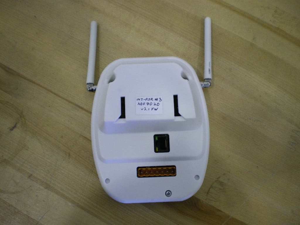
ISEIPSR
Dec 02, 2010434MHz International Patient Security Receiver
Equipment Class
CYY - Communications Receiver used w/Pt 15 Transmitter
ISEXCR
Oct 16, 2007Transceiver Exciter
Equipment Class
DCD - Part 15 Low Power Transmitter Below 1705 kHz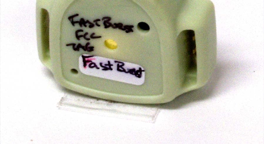
ISEH2H
Jun 20, 2006Infant Tag
Equipment Class
DSR - Part 15 Remote Control/Security Device Transceiver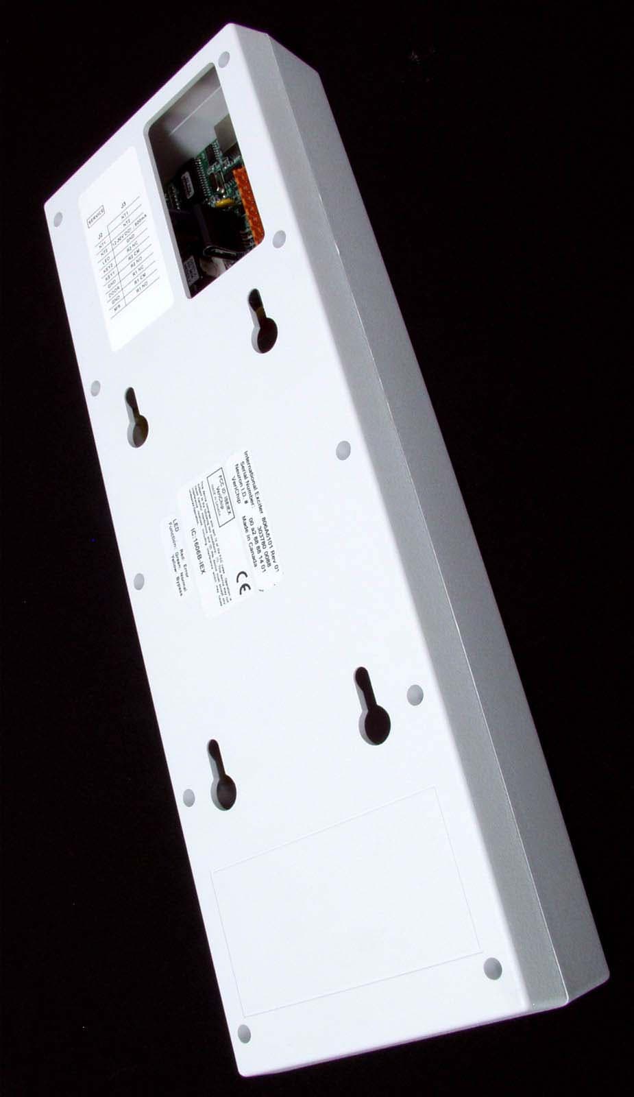
ISEIEX
Aug 25, 2005Low Power Transmitter
Equipment Class
DCD - Part 15 Low Power Transmitter Below 1705 kHz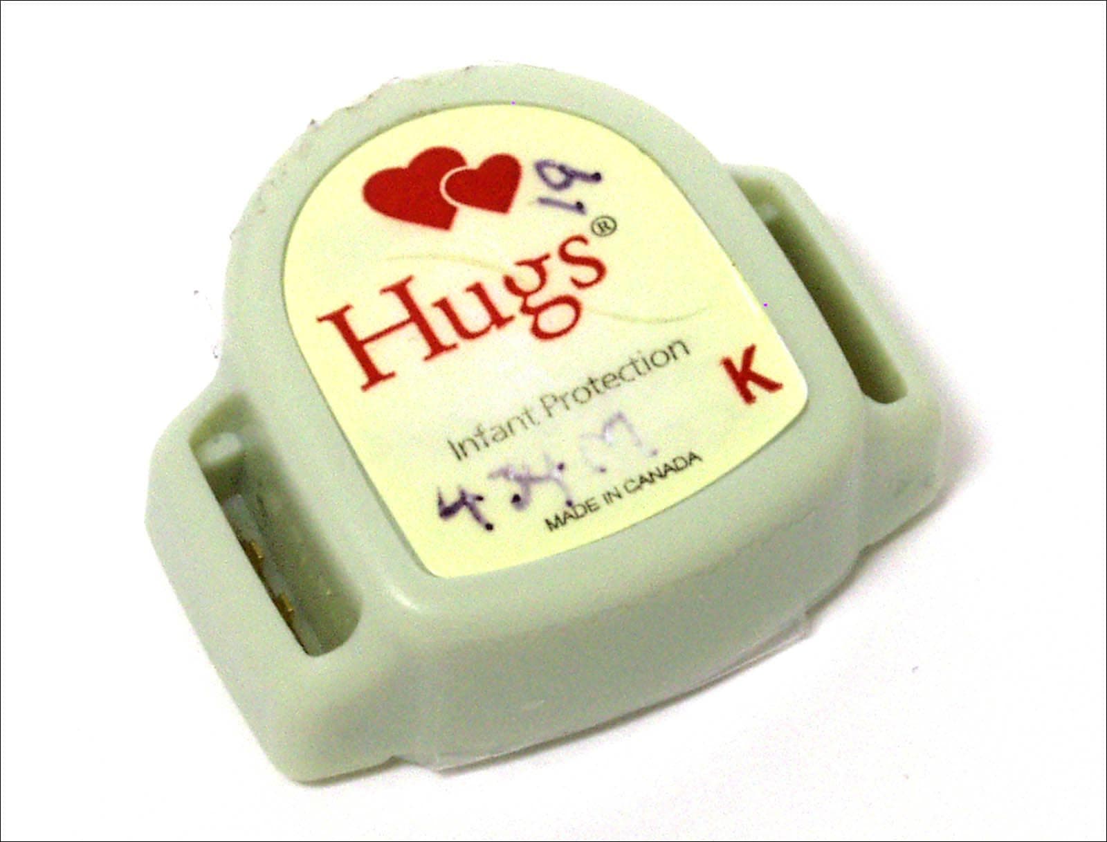
ISEITG
Mar 14, 2005International Hugs Tag 806A5201
Equipment Class
DSR - Part 15 Remote Control/Security Device Transceiver