ISEXLXLarge Exciter
Xmark Corporation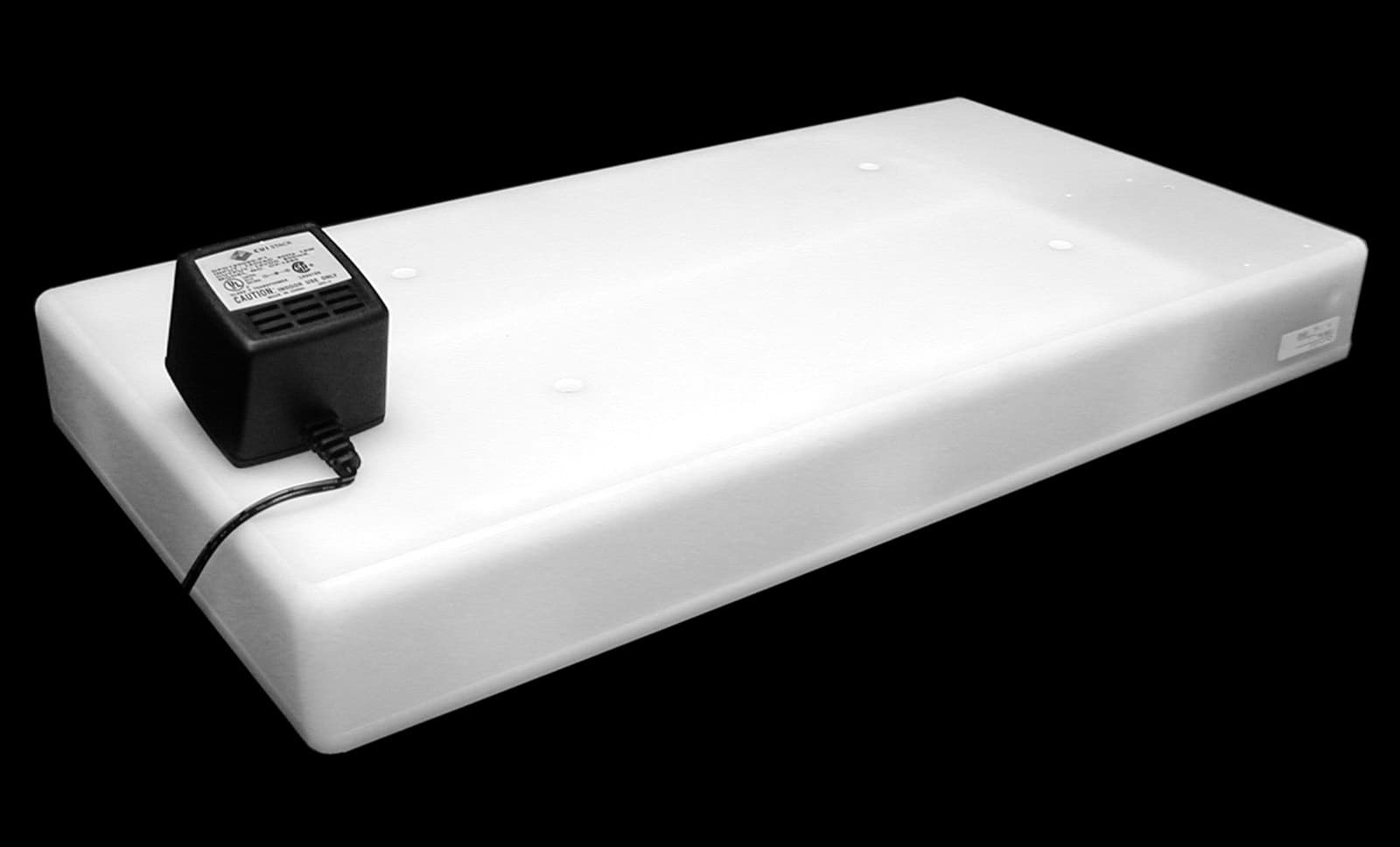
Click to zoom
Application Details
- Equipment Class
- DCD - Part 15 Low Power Transmitter Below 1705 kHz
- Date of Grant
- Dec 02, 2002
- Application Purpose
- Original Equipment
- Date of Application
- Dec 02, 2002
- Equipment Note
- Large Exciter
- Frequency Range
- 0.31250000 - 0.31250000
- Company
- Xmark Corporation
- Country
- Canada
Documents & Files
Document Text
Text extracted from the exhibit documents filed with the FCC. Open a document above to read the original.
Users Manual
Large Exciter Instructions Part Number 805A6201 309 Legget Drive, Ottawa, ON K2K 3A3, Canada or 808 Commerce Park Drive, Ogdensburg, NY 13669 USA Telephone: 1-613-592-4642 Facsimile: 1-613-592-4296 Web Site: www.xmarksystems.com © 2002 Instantel Inc. All Rights Reserved. Instantel and Hugs are registered trademarks of Instantel Inc. in North America. The hearts logo and Xmark are trademarks of Instantel Inc. Xmark is a division of Instantel Inc. Printed in Canada. November 2002. 805U6201 Rev B. Certifi ed to the ISO 9001 Quality Standard Materials Required • Exciter. Includes door contact, ferrite core (p/n 28A2029-0A2) and terminal blocks. • Facility fl oor plan indicating Exciter position and installation orientation, and network wiring path. • 105 Ω network terminator (p/n 805A2401) required to terminate network. Two provided with each Controller (p/n 805A2201) or Laptop Controller (p/n 805A2202). • Suitable mounting hardware, such as wall anchors • Optional: Passive infrared sensor for open doorways where door contact cannot be used. Refer to Chapter 2 of the Hugs Instal- lation Manual (p/n 805I0301) for important limitations on using PIR sensors. Specifi cations Read these instructions thoroughly before installing the Exciter. Faulty installation can lead to system failure. ! Installation Considerations • Avoid metal—Do not install the Exciter behind or within 2 inches (50 mm) of metal objects, including metal doors. These objects block the detection area of the Exciter. • Use door contacts—Door contacts are required to minimize nuisance alarms. • Confi gure nearby Exciters as slaves—Exciters installed within 30 feet (9 m) of each other must be confi gured as master and slave. Up to four slaves may be connected to one master. • Use the supplied ferrite core—Wrap the power cable around the supplied ferrite core, as explained in the instructions. Failure to do so will void the user’s authority to operate the equipment. • Observe temperature and humidity restrictions—Refer to the Specifi cations table. • Leave slack in the cable—Leave at least 10 ft. (3 m) of slack in the communication and power cable to allow for adjustments in the location of the Exciter. • No user adjustments to internal circuitry—Tampering may cause component or system failure, or both, and will void the warranty. Important Reference Documents • Hugs Installation Manual (p/n 805I0301) Refer to Chapter 2 of the Hugs Installation Manual for detailed information on detection areas, installation options, master/slave confi gurations and software settings. • Hugs System Manual (p/n 805U1601) • Exciter Tester Sheet (p/n 805U2101) Materials Required Specifi cations Installation Considerations Important Reference Documents Have you: • Pulled network and power cable? • Resolved power supply requirements? • Selected Exciter orientation and position? If you answered, “No,” to any of these questions, refer to the Hugs Installation Manual before installing. Frequency312.5 kHz Supply10-30 VDC Current Draw200 mA @ 24 VDC, 800 mA maximum Relay Outputs (2)30 VDC, 1 A, NO or NC Detection radiusAdjustable, up to 11 ft. CommunicationsLonWorks two-wire Temperature - operating32° to 122° F (0° to 50° C) Temperature - storage-40° to 176° F (-40° to 80° C) Humidity0 - 90% RH @ 70° F (21° C) DimensionsApprox 20.7 x 10.9 x 2.3 in. (526 x 275 x 60 mm) WeightApproximately 6 lbs. (2.7 kg) Installing the Exciter • Ensure that the power supply and network are turned off to prevent electrical shock or damage to equip- ment. • Touch your hand to ground to discharge any electro- static charge before handling the Exciter. 1 Locate and record the LonWorks identifi cation number onto the facility fl oor plan indicating the Exciter’s position and network wiring path. Use the tear-away sticker on the Exciter’s Neuron ID label. 2 Install the supplied door contact or PIR sensor according to the manufacturer’s instructions and connect it to the terminal, as shown in the wiring diagrams. Connect the LonWorks Network IN, Network OUT, and Power Supply to the terminal blocks, as shown in the wiring diagrams. Wrap the Power Supply cable around Item B (ferrite core); DO NOT use substitutes. If the Exciter is at the end of the network, then terminate the net- work segment with Item A (105 Ω terminator). Refer to Figure 1, and insert the terminals into the connectors on the Exciter. Note: If installing keypads or accessory devices, or if using a master/slave confi guration, proceed to the relevant sections on the opposite page, and then return to steps 3 and 4. 3 Ensure that the status LED of the Exciter (located on the bottom of the case) will be visible. Refer to the facility fl oor plan for location, and using the Exciter as a template mark the location of the four mounting holes. Drill the holes. 4 Mount the Exciter: A Install in the four mounting holes: 4 hollow wall anchors B Insert into the wall anchors, leaving 3/8 in. (0.5 cm) of the shaft exposed: 4 No. 12 wood screws x 2 in. long C If using surface wire conduit, attach the four supplied bumpons (Item B in Figure 1) to the underside of the Exciter. D Align the Exciter with the mounting screws, and while lightly pressing, slide until it is securely in place. Insert the supplied screw caps. Installation is complete. Proceed to Final Steps below. ! Installing Keypads Refer to the wiring diagrams below and the manufacturer’s instructions. Keypads may be connected to either master or slave Exciter. Notes: • Either one Wiegand or two Corby keypads can be connected to an Exciter. • The Wiegand and Corby keypads cannot be connected to the same Exciter. • The Wiegand keypad requires a 12 VDC power supply; set the central Power Supply to 12 V for this application. • Corby keypads may be powered at 12 or 24 VDC. If connected at 24 V, they require a 1 kW, 1/4 Ω resistor connected between the power supply and each keypad LED. Refer to Figure 2 below. Installing Accessory Devices Each Exciter has two 30 VDC, 1 Amp, NO…
Text truncated - open the document above for the full version.
Cover Letter(s)
Barry Quinlan From: "Ruby Dulmage" <[email protected]> To: "Barry Quinlan - Curtis-Straus" <[email protected]> Sent: Tuesday, November 26, 2002 3:27 PM Attach: 2W06569 Issue II.PDF; Test setup photos - Radiated.pdf; 805A6201 REV B HIGH PWR EXCITER UNIT ASSY Model (1).pdf; 805A6201 REV B SHT 2 HIGH PWR EXCITER UNIT ASSY Model (1).pdf; 805A6201 REV B SHT 3 HIGH PWR EXCITER UNIT ASSY Model (1).pdf; 805U620_ RevB.pdf; FCC letter.pdf; Test Configuration photos.pdf; Test set-up photo - Power Line Conducted.pdf; 805A6201 REV B BOM.pdf Sub ject: Fw: Answers - Re: Instantel FCC ID: ISEXLX Page 1 of 2 12/3/2002 Hi Barry: Here is the email again. Thanks, Ruby ----- Original Message ----- From: Ruby Dulmage To: Curtis -Straus TCB Sent: Monday, November 11, 2002 11:53 AM Subject: Answers - Re: Instantel FCC ID: ISEXLX Hi Barry: Please see my answers (in blue) below your questions. I have attached the following: - Confidentiality request letter on letterhead - Revised user guide - Revised BOM - Revised Assembly drawings - Revised test report - Test setup photos - Test configuration photos I trust this information will enable you to complete this submission. Thanks, Ruby Ruby Dulmage Submissions Specialist Nemko Canada Inc. 303 River Road, R.R. 5 Ottawa, ON K1V 1H2 Tel: 613-737-9680 ext 232 Fax: 613-737-9691 Email: [email protected] ----- Original Message ----- From: Curtis -Straus TCB To: Ruby Dulmage Sent: Thursday, October 31, 2002 2:34 PM Subject: Instantel FCC ID: ISEXLX Hi Rub y, We have identified these issues following our review of the application: 1. Please provide conducted emissions test data with a typical OEM power supply. See revised test report attached - refer to pages 7 to 10 2. The unit incorporates a 5 MHz clock timing source. Please provide radiated emissions test data covering the additional range from 3.15MHz-1000MHZ per 15.33(a)(4). See revised test report attached - refer to pages 11 & 12 3. Please provide a test configuration photograph in which it is possible to see the configuration. Do not take the photograph from 10 meters away. See test setup photos and configuration photos attached 4. Please provide a detailed description of the test configuration including any cables attached to the EUT. Please describe the cables by length, shielding status, and if any ferrites are attached. See revised test report - refer to pages 11 to 14 5. Please provide data responsive to 15.31(e) voltage variations. See revised test report - refer to page 11 6. Please provide the confidentiality request on company letter headed paper. See revised confidentiality request attached. 7. The manual does not appear to contain the 15.21 statement. See revised user guide attached. Page 2 of 2 12/3/2002
Cover Letter(s)
Barry Quinlan From: "Ruby Dulmage" <[email protected]> To: "Barry Quinlan - Curtis-Straus" <[email protected]> Sent: Thursday, November 28, 2002 11:42 AM Attach: 2W06569 Issue III.PDF; Revised radiated test setup photos.pdf Sub ject: Fw: Answers - Re: Instantel FCC ID: ISEXLX - Nov 28-02 Page 1 of 1 12/3/2002 Hi Barry: 1. Please revised revised test report attached. 2. We believe the internal can be kept confidential because they are NOT viewable by the public or sold to the general public. It is professional installed by personnel who are under strict confidentiality. All of Instantel's applications have been granted confidentiality of the internal photos based on this in the past. 3. A revised radiated test setup photo is attached. Thanks, Ruby ----- Original Message ----- From: Curtis -Straus Certification Dept. To: Ruby Dulmage Sent: Wednesday, November 27, 2002 2:29 PM Subject: Re: Answers - Re: Instantel FCC ID: ISEXLX Hi Ruby, Sorry our email filter deleted the first email. We have these issues following your responses: 1. From the test setup photo it appears the line conducted testing was performed on a deficient configuration. Please provide line conducted data collected with the control ports populated with 1 meter wires. 2. It is not permissible for the internal photos to be considered confidential for this device as the installer and user are able to gain access to the internals. Please supply a revised confidentiality request. 3. The radiated test setup photo is very dark. Can you supply a new or modified version? Best regards Barry C. Quinlan Certification Manager Curtis-Straus TCB
ID Label/Location Info
FCC ID: ISEXLX INSTANTEL INC. MADE IN CANADA This device complies with part 15 of the FCC rules. Operation is subject to the following two conditions: (1) This device may not cause harmful interference, and (2) this device must accept any interference received, including interference which may cause undesired Operation. IC: 1606B-XLX
Test Report
Master: PT15209 Date: December 12, 2001 Test Report:2W06569 Issue III Applicant:Instantel Inc. 309 Legget Drive Kanata, Ontario K2K 3A3 Equipment Under Test:XMARK Large Exciter (EUT)312.5KHz Transmitter FCC ID:ISEXLX In Accordance With:FCC Part 15, Subpart C Tested By:Nemko Canada Inc. 303 River Road, R.R. 5 Ottawa, Ontario K1V 1H2 Authorized By: Kevin Carr, EMC Specialist Date:28 November 2002 Total Number of Pages:17 Nemko Canada Inc.FCC PART 15, SUBPART C, 15.209 PROJECT NO.:2W06569, Issue III EQUIPMENT:XMARK Large Exciter Page 2 of 17 Table Of Contents Section 1. Summary Of Test Results.....................................................................................3 Section 2. General Equipment Specification........................................................................5 Section 3. Radiated Emissions.............................................................................................12 Section 4. Block Diagrams...................................................................................................16 Section 5. Test Equipment List...........................................................................................17 Nemko Canada Inc.FCC PART 15, SUBPART C, 15.209 PROJECT NO.:2W06569, Issue III EQUIPMENT:XMARK Large Exciter Page 3 of 17 Section 1.Summary Of Test Results General All measurements are traceable to national standards. These tests were conducted on a sample of the equipment for the purpose of demonstrating compliance with FCC Part 15, Subpart C, 15.209. All tests were conducted using measurement procedure ANSI C63.4-1992. Radiated Emissions were made on an open area test site. A description of the test facility in on file with the FCC. THIS TEST REPORT RELATES ONLY TO THE ITEM(S) TESTED. TESTED BY: _______________________________DATE: 28 November 2002 Glen Westwell, Wireless Technologist Nemko Canada Inc. authorizes the above named company to reproduce this report provided it is reproduced in its entirety and for use by the company’s employees only. Any use which a third party makes of this report, or any reliance on or decisions to be made based on it, are the responsibility of such third parties. Nemko Canada Inc. accepts no responsibility for damages, if any, suffered by any third party as a result of decisions made or actions based on this report. This report applies only to the items tested. Nemko Canada Inc.FCC PART 15, SUBPART C, 15.209 PROJECT NO.:2W06569, Issue III EQUIPMENT:XMARK Large Exciter Page 4 of 17 Summary Of Test Data Name Of TestPara. No.Result Powerline Conducted Emissions15.207Complies Radiated Emissions15.209Complies Notes: This unit is power by an external OEM 12Vdc source. Ferrite 28A-20290A2 was used at the DC input power line to reduce emissions detected at 30 & 60MHz. This ferrite has been incorportated in the B.O.M (see set up photo’s). Test Conditions: IndoorTemperature:24°C Humidity:34% OutdoorTemperature:17°C Humidity:31% Nemko Canada Inc.FCC PART 15, SUBPART C, 15.209 PROJECT NO.:2W06569, Issue III EQUIPMENT:XMARK Large Exciter Page 5 of 17 Section 2.General Equipment Specification Manufacturer: Instantel Inc. Model No.: 805A6201 Serial No.: none Date Received In Laboratory: 21 Oct. 2002 Nemko Identification No.: 1 Transmit Frequency (fixed) 312.5KHz Type of Modulation: On/Off Keying (OOK) Emission designator: 16K2POD Nemko Canada Inc.FCC PART 15, SUBPART C, 15.209 PROJECT NO.:2W06569, Issue III EQUIPMENT:XMARK Large Exciter Page 6 of 17 99% Occupied Bandwidth Nemko Canada Inc.FCC PART 15, SUBPART C, 15.209 PROJECT NO.:2W06569, Issue III EQUIPMENT:XMARK Large Exciter Page 7 of 17 Section 3.Powerline Conducted Emissions Para. No.: 15.207 Test Performed By: Glen WestwellDate of Test: 1 Nov 2002 Minimum Standard: FrequencyMaximum Powerline Conducted RF Voltage (MHz) (μμV)(dBμμV) 0.45 - 30.025048 Test Results:Complies. Measurement Data:See attached tables & graph(s). Nemko Canada Inc.FCC PART 15, SUBPART C, 15.209 PROJECT NO.:2W06569, Issue III EQUIPMENT:XMARK Large Exciter Page 8 of 17 No Ferrite installed on AC Power Line Class B Mains limits (Neutral) No.Frequency of Emission (MHz) DetectorEmission Level (dBV) Limit (dBuV) BB / NB BB Corr. (dB) Result (dB) 1 30.0000Quasi-Peak54.248.0BB136.8 30.0000Average39BB13 2 0.6300Quasi-Peak55.448.0BB135.6 0.6300Average31.7BB13 3 29.1100Quasi-Peak47.948.0BB1313.1 29.1100Average29.1BB13 4 29.7000Quasi-Peak47.848.0BB1313.2 29.7000Average29.1BB13 5 28.4600Quasi-Peak42.948.0BB1318.1 28.4600Average26.2BB13 6 29.4100Quasi-Peak41.548.0BB1319.5 29.4100Average26.4BB13 Class B Mains limits (Phase) No.Frequency of Emission (MHz) DetectorEmission Level (dBV) Limit (dBuV) BB / NB BB Corr. (dB) Result (dB) 1 30.0000Quasi-Peak5548.0BB136.0 30.0000Average39.1BB13 2 29.7000Quasi-Peak47.948.0BB1313.1 29.7000Average29BB13 3 27.8100Quasi-Peak48.348.0BB1312.7 27.8100Average29BB13 4 27.5200Quasi-Peak4348.0BB1318.0 27.5200Average29BB13 5 28.1100Quasi-Peak34.148.0BB1326.9 28.1100Average21.6BB13 6 29.3500Quasi-Peak33.248.0BB1327.8 29.3500Average21.6BB13 Nemko Canada Inc.FCC PART 15, SUBPART C, 15.209 PROJECT NO.:2W06569, Issue III EQUIPMENT:XMARK Large Exciter Page 9 of 17 No Ferrite installed on AC Power Line Nemko Canada Inc.FCC PART 15, SUBPART C, 15.209 PROJECT NO.:2W06569, Issue III EQUIPMENT:XMARK Large Exciter Page 10 of 17 28A-20290A2 Ferrite installed on AC Power Line Nemko Canada Inc.FCC PART 15, SUBPART C, 15.209 PROJECT NO.:2W06569, Issue III EQUIPMENT:XMARK Large Exciter Page 11 of 17 Power Line Conducted Photo No Ferrite on AC Power Line 28A-20290A2 Ferrite installed on AC Power Line Nemko Canada Inc.FCC PART 15, SUBPART C, 15.209 PROJECT NO.:2W06569, Issue III EQUIPMENT:XMARK Large Exciter Page 12 of 17 Section 3.Radiated Emissions Para. No.: 15.209 Test Performed By: Glen WestwellDate of Test: 21 Oct. 2002 Minimum Standard: Tx = 312KHz Fundamental (MHz) Field Strength (μμV/m) Field Strength (dBμμV) 0.009 - 0.4902400/F(kHz) @ 300m17.7 0.490 - 1.70524000/F(kHz) @ 30m— 1.705 - …
Text truncated - open the document above for the full version.
Test Setup Photos
Nemko Canada Inc.FCC PART 15, SUBPART C, 15.209 PROJECT NO.:2W06569, Issue III EQUIPMENT:XMARK Large Exciter Page 14 of 17 All harmonic and spurious emissions were searched up to the 10 th harmonic Photo, Test Set-up Nemko Canada Inc.FCC PART 15, SUBPART C, 15.209 PROJECT NO.:2W06569, Issue III EQUIPMENT:XMARK Large Exciter Page 15 of 17 Test Configuaration Ferrite on Power Line
Contact Information
Applicant
Peter Rousseau(RF Technologist)
Test Firm
Nemko Canada Inc.Stuart Beck
Technical Specifications
| # | Rule Parts | Frequency Range | Power Output |
|---|---|---|---|
| 1 | 15C | 0.3125 MHz - 0.3125 MHz | - |
Other Applications from Xmark Corporation
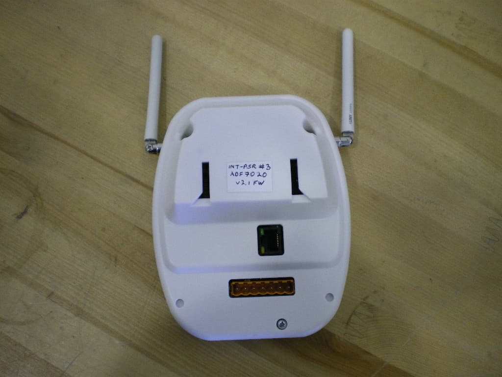
ISEIPSR
Dec 02, 2010434MHz International Patient Security Receiver
Equipment Class
CYY - Communications Receiver used w/Pt 15 Transmitter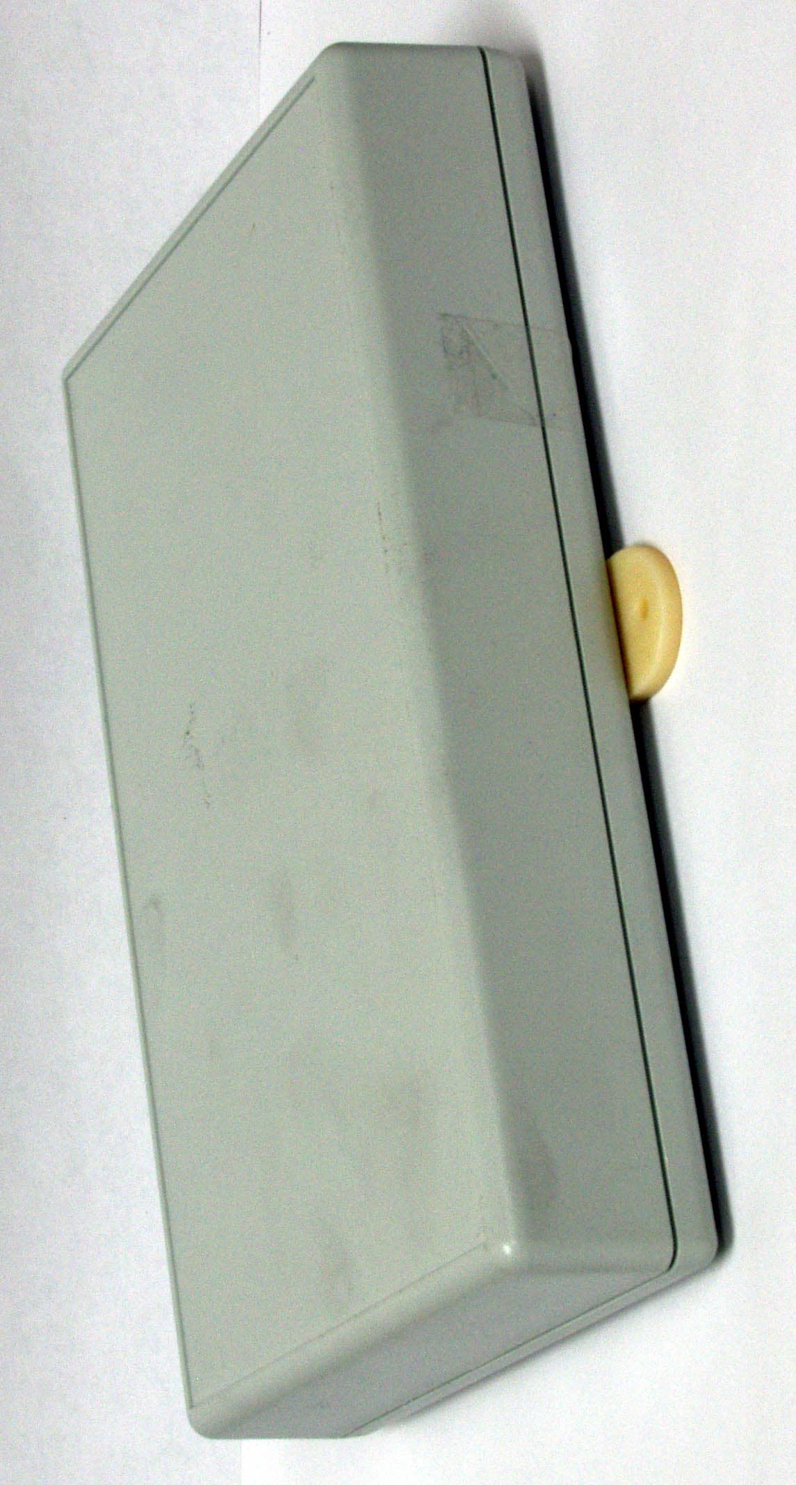
ISEXCR
Oct 16, 2007Transceiver Exciter
Equipment Class
DCD - Part 15 Low Power Transmitter Below 1705 kHz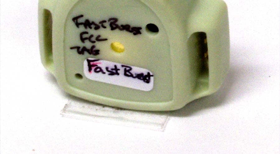
ISEH2H
Jun 20, 2006Infant Tag
Equipment Class
DSR - Part 15 Remote Control/Security Device Transceiver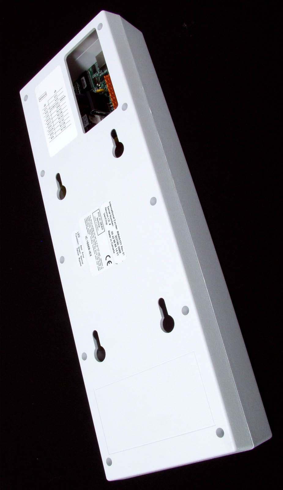
ISEIEX
Aug 25, 2005Low Power Transmitter
Equipment Class
DCD - Part 15 Low Power Transmitter Below 1705 kHz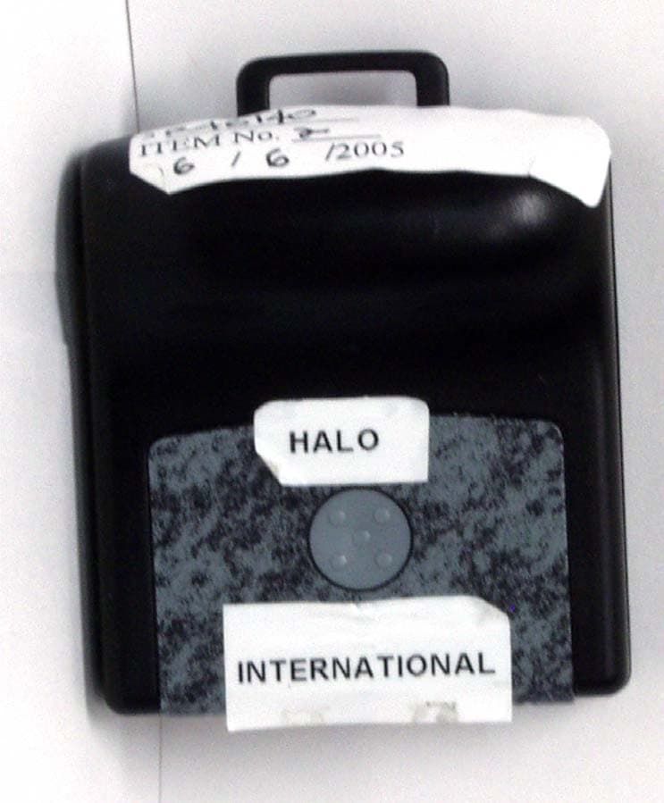
ISEIMF
Jun 23, 2005Communicator Tag
Equipment Class
DSC - Part 15 Security/Remote Control Transmitter