IWK-EX845EX845 Meter with IR Thermometer
FLIR Commercial Systems, Inc.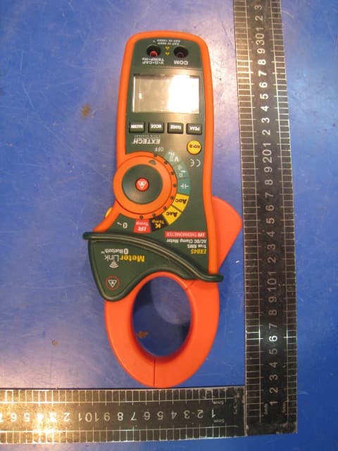
Click to zoom
Application Details
- Equipment Class
- DSS - Part 15 Spread Spectrum Transmitter
- Date of Grant
- Apr 14, 2010
- Application Purpose
- Original Equipment
- Date of Application
- Apr 14, 2010
- Equipment Note
- EX845 Meter with IR Thermometer
- Frequency Range
- 2402.00000000 - 2480.00000000
- Country
- United States
Documents & Files
Document Text
Text extracted from the exhibit documents filed with the FCC. Open a document above to read the original.
Users Manual
User's Guide Bluetooth Series 1000 Amp Clamp Meters with IR Thermometer AC/DC True RMS Clamp meter Patented 2 Introduction 1000A True RMS AC/DC Current Clamp models measure: Infrared Temperature AC/DC Voltage Resistance Capacitance Frequency Continuity Diode Specific functions: DC Current, True RMS, Type K thermometer, DC Zero Auto Power OFF Max/Min recording Data Hold Peak Hold Backlit LCD display Careful use of this meter will provide many years of reliable service. 3 Safety International Safety Symbols This symbol, adjacent to another symbol or terminal, indicates the user must refer to the manual for further information. This symbol, adjacent to a terminal, indicates that, under normal use, hazardous voltages may be present Double insulation SAFETY NOTES • Do not exceed the maximum allowable input range of any function. • Do not apply voltage to meter when resistance function is selected. • Set the function switch OFF when the meter is not in use. • Remove the battery if meter is to be stored for longer than 60 days. WARNINGS • Set function switch to the appropriate position before measuring. • When measuring volts do not switch to current/resistance modes. • Do not measure current on a circuit whose voltage exceeds 600V. • When changing ranges always disconnect the test leads from the circuit under test. • Bluetooth UL Note A UL mark does not indicate that this product has been evaluated for accuracy. CAUTIONS • Improper use of this meter can cause damage, shock, injury or death. Read and understand this user manual before operating the meter. • Always remove the test leads before replacing the battery or fuses. • Inspect the condition of the test leads and the meter itself for any damage before operating the meter. Repair or replace any damage before use. • Use great care when making measurements if the voltages are greater than 25VAC rms or 35VDC. These voltages are considered a shock hazard. • Always discharge capacitors and remove power from the device under test before performing Diode, Resistance or Continuity tests. • Voltage checks on electrical outlets can be difficult and misleading because of the uncertainty of connection to the recessed electrical contacts. Other means should be used to ensure that the terminals are not "live". • If the equipment is used in a manner not specified by the manufacturer, the protection provided by the equipment may be impaired. Function Maximum Input A AC, A DC 1000A DC/AC V DC, V AC 600V DC/AC Resistance, Capacitance, Frequency, Diode Test250V DC/AC Type K Temperature 60V DC, 24V AC 4 Description eter Description 1. Current clamp 2. Clamp opening trigger 3. Data Hold Button 4. Mode 5. Peak 6. Range 7. DCA Zero 8. MIN/MAX 9. Backlit LCD Display 10. Test lead input jacks 11. IR thermometer and laser pointer (rear) 12. Backlight /BT active / Store trigger button 13. Laser pointer button 14. Function switch Display icons Description HOLD Data Hold Minus sign Negative reading display 0 to 3999 Measurement display digits ZERO DCA Zero P Peak value AUTO Auto Range mode DC/AC Direct Current / Alternating Current MAX Max reading MIN Min reading Low battery mV or V Milli-volts or Volts (Voltage) Ω Ohms (Resistance) A Amperes (Current) F Farad (Capacitance) Hz Hertz (Frequency) o F and o C Fahrenheit and Celsius units (Temperature) n, m, μ, M, k Unit of measure prefixes: nano, milli, micro, mega, and kilo • ) ) ) Continuity test Diode test Laser pointer BT active 5 Specifications Function Range & Resolution Accuracy (% of reading + digits) 400.0 AAC ± (2.5% + 8d) AC Current 50/60 Hz True RMS 1000 AAC ± (2.8% + 5d) 400.0 ADC ± (2.5% + 5d) DC Current 1000 ADC ± (2.8% + 5d) 400.0 mVAC ± (1.0% + 10d) 4.000 VAC 40.00 VAC 400.0 VAC ± (1.5% + 5d) AC Voltage 50/60Hz True RMS 600 VAC ± (2.0% + 5d) 400.0 mVDC ± (0.8% + 2d) 4.000 VDC 40.00 VDC 400.0 VDC ± (1.5% + 2d) DC Voltage 600 VDC ± (2.0% + 2d) 400.0Ω ± (1.0% + 4d) 4.000kΩ 40.000kΩ 400.0kΩ ± (1.5% + 2d) 4.000MΩ ± (2.5% + 3d) Resistance 40.00MΩ ± (3.5% + 5d) 4.000nF ± (5.0% + 30d) 40.00nF ± (5.0% + 20d) 400.0nF 4.000μF 40.00μF ± (3.0% + 5d) 400.0μF ± (4.0% + 10d) 4.000mF ± (10% + 10d) Capacitance 40.00mF unspecified 4.000kHz ± (1.5% + 2d) Frequency Sensitivity: 100V (<50Hz); 50V (50 to 400Hz); 5V (401Hz to 4000Hz) 6 Function Range and Resolution Accuracy (% of reading + digits) -4 to 1400 o F ± (3%rdg + 9 o F) Temperature (type-K) -20 to 760 o C ± (3%rdg + 5 o C) -58 to -4°F ± 9 °F -4 to 518°F ±2.0% reading or ± 4°F whichever is > -50 to -20°C ±5°C Temp (IR) -20 to 270°C ±2.0% reading or ±2°C General Specifications Clamp jaw opening 1.7" (43mm) approx. Display 3-3/4 digits (4000 counts) backlit LCD Continuity check Threshold 40Ω; Test current < 0.5mA Diode test Test current of 0.3mA typical; Open circuit voltage < 3VDC typical Low Battery indication Battery symbol is displayed Over-range indication ‘OL’ display Measurement rate 2 readings per second, nominal PEAK Captures peaks >1ms Thermocouple sensor Type K thermocouple required IR Spectral response 6 to 16μm IR Emissivity 0.95 fixed IR distance ratio 8:1 Input Impedance 10MΩ (VDC and VAC) AC bandwidth 50 to 400Hz (AAC and VAC) AC response True rms (AAC and VAC) Crest Factor 3.0 in 40A and 400A ranges, 1.4 in 1000A range (50/60Hz and 5% to 100% of range) Operating Temperature 41°F to 104°F (5°C to 40°C) Storage Temperature -4°F to 140°F (-20°C to 60°C) Operating Humidity Max 80% up to 87°F (31°C) decreasing linearly to 50% at 104°F(40°C) Storage Humidity <80% Operating Altitude 7000ft. (2000meters) maximum. Battery One (1) 9V Battery (NEDA 1604) Auto power OFF After approx. 25 minutes Dimensions & Weight 10.6x4.3x2” (270x110x50mm); 13.6 oz. (386g) Safety For indoor use and in accordance with the requirements for double insulation to IEC1010-1 (2001): EN61010-1 (2001) Overvoltage Category III 600V and Category II 1000V, Pollution Degree 2. 7 Operation NOTES: Read and understand all Warning and Caution statements in this operation m…
Text truncated - open the document above for the full version.
Attestation Statements
Hopping Information 1. Hopping Range Hereby we declare that the maximum frequency of this device is: 2402-2480MHz. This is according the Bluetooth Core Specification V1.2 for devices which will be operated in the Europe. This was checked during the Bluetooth Qualification tests. Other frequency ranges (e.g. for USA, China, Japan) which are allowed according the Core Specification are not supported by this device. 2. Hopping Sequence Example of a 79 hopping sequence in data mode: 33,04,21,44,23,42,53,46,55,48,40,59,72,29,76,31,08,73, 07,75,09,45,60,39,58,13,47,11,77,52,35,50,65,54,67,56, 69,62,71,64, 37,25,27,66,57,70,74,61,78,63,10,41,05,43, 15,44,64,68,02,70,06,01,51,03,55,05,03,66,53,49,36,47. 3. Receiver input bandwidth The input bandwidth of the receiver is 1MHz. In every connection one Bluetooth device is the master and the other one is the slave. The master determines the hopping sequence. The slave follows this sequence. Both devices shift between RX and TX time slot according to the clock of the master. Additionally the type of connection is set up at the beginning of the connection. The master adapts its hopping frequency and its TX/RX timing according to the packet type of the connection. Also the slave of the connection will use these settings. Repeating of a packer has no influence on the hopping sequence. The hopping sequence generated by the master of the connection will be followed in any case. That means a repeated packet will not be send on the same frequency, it is send on the next frequency of the hopping sequence.
External Photos
Page 1/2 Report No.:WT108000074 Page 1 of 2 APPENDIX II EUT Photo Page 2/ Report No.:WT108000074 Page 2 of 2 Photo 1 Appearance of EUT Photo 2 Appearance of EUT Label location
ID Label/Location Info
Page 2/ Report No.:WT108000074 Page 2 of 2 Label location
Internal Photos
Page 1/5 Report No.:WT108000074 Page 1 of 5 APPENDIX III EUT Photo Page 2/ Report No.:WT108000074 Page 2 of 5 Photo 1 Inside of EUT (with RF module and antenna) Photo 2 Bluetooth Module (top) Antenna Page 3/ Report No.:WT108000074 Page 3 of 5 Photo 3 Bluetooth Module (bottom) Photo 4 Inside of EUT Page 4/ Report No.:WT108000074 Page 4 of 5 Photo 5 Inside of EUT Photo 6 Inside of EUT Page 5/ Report No.:WT108000074 Page 5 of 5 Photo 7 Inside of EUT
Test Report
Page 1/62 FCC TEST REPORT For EXTECH EX845 TRUE RMS 1000 Amp Clamp Meter with IR Thermometer Model Number: EX845 FCC ID: IWK-EX845 Report Number: WT108000074 Test Laboratory : Shenzhen Academy of Metrology and Quality Inspection National Testing Center for Digital Electronic Products Site Location : Bldg. Metrology and Quality Inspection, Longzhu Road, Shenzhen, Guangdong, China Tel : 0086-755-26941599 Fax : 0086-755-26941545 Web : www.smq.com.cn Report No.:WT108000074 Page 2 of 62 Test report declaration Applicant : Extech Instruments Corporation Address : 285 Bear Hill Road Waltham, MA 02451, USA Manufacturer : SHENZHEN EVERBEST MACHINERY INDUSTRY CO.,LTD. Address : 19th Building, 5th Region, Baiwangxin Industrial Park, Songbai Rd., Baimang, Xili,Nanshan, Shenzhen, China EUT Description : EXTECH EX845 TRUE RMS 1000 Amp Clamp Meter with IR Thermometer Model No : EX845 Trade mark : EXTECH Serial Number : 090604238 FCC ID : IWK-EX845 Test Standards: FCC Part 15, Subpart C, §15.247 The EUT described above is tested by Shenzhen Academy of Metrology and Quality Inspection EMC Laboratory to determine the maximum emissions from the EUT. Shenzhen Academy of Metrology and Quality Inspection EMC Laboratory is assumed full responsibility for the accuracy of the test results. The test data, data evaluation, test procedures, and equipment configurations shown in this report were made in accordance with the procedures given in ANSI C63.4 (2003) and the energy emitted by the sample EUT tested as described in this report is in compliance with FCC Rules §15.109, §15.203, §15.205, §15.209 and §15.247. The test report is valid for above tested sample only and shall not be reproduced in part without written approval of the laboratory. Project Engineer: Date: April 8, 2010 (Bill Yi) Checked by: Date: April 8, 2010 (Ryan Chen) Approved by: Date: April 8, 2010 (Peter Lin) Report No.:WT108000074 Page 3 of 62 TABLE OF CONTENTS TEST REPORT DECLARATION........................................................................................................2 1. TEST RESULTS SUMMARY...................................................................................................5 2. GENERAL INFORMATION......................................................................................................6 2.1. Report information..........................................................................................................6 2.2. Laboratory Accreditation and Relationship to Customer.........................................6 2.3. Measurement Uncertainty.............................................................................................7 3. PRODUCT DESCRIPTION......................................................................................................8 3.1. EUT Description..............................................................................................................8 3.2. Related Submittal(s) / Grant (s)...................................................................................8 3.3. Block Diagram of EUT Configuration..........................................................................9 3.4. Operating Condition of EUT..........................................................................................9 3.5. Support Equipment List.................................................................................................9 3.6. Test Conditions...............................................................................................................9 3.7. Special Accessories.......................................................................................................9 3.8. Equipment Modifications...............................................................................................9 3.9. Test Methodology.........................................................................................................10 4. TEST EQUIPMENT USED.....................................................................................................11 5. RF EXPOSURE........................................................................................................................12 5.1. Test Standard and Limit..............................................................................................12 5.2. Test Data.......................................................................................................................12 6. ANTENNA REQUIREMENT...................................................................................................14 6.1. Test Standard and Limit..............................................................................................14 6.2. Result.............................................................................................................................14 7. RADIATED SPURIOUS EMISSIONS TEST.......................................................................15 7.1. Test Standard and Limit..............................................................................................15 7.2. Test Procedure.............................................................................................................15 7.3. Test Arrangement.........................................................................................................16 7.4. Test Data.......................................................................................................................17 8. CHANNEL SEPARATION TEST...........................................................................................32 Report No.:WT108000074 Page 4 of 62 8.1. Test Standard and Limit..............................................................................................32 8.2. Test Procedure.............................................................................................................32 8.3. Test Data.....................................................................................................…
Text truncated - open the document above for the full version.
Test Setup Photos
Page 1/3 Report No.:WT108000074 Page 1 of 3 APPENDIX I TEST PHOTOS Page 2/ Report No.:WT108000074 Page 2 of 3 Photo 1 Front of Radiated Disturbance Test (Below 1GHz) Photo 2 Rear of Radiated Disturbance Test (Below 1GHz) Page 3/ Report No.:WT108000074 Page 3 of 3 Photo 3 Front of Radiated Disturbance Test (Above 1GHz) Photo 4 Rear of Radiated Disturbance Test (Above 1GHz)
Contact Information
Applicant
Mark Sultzbach(QA Administrator)
Test Firm
Shenzhen Academy of Metrology & Quality InspectionPeter Lin
Technical Specifications
| # | Rule Parts | Frequency Range | Power Output |
|---|---|---|---|
| 1 | 15C | 2.40 GHz - 2.48 GHz | 360.00 µW |
Other Applications from FLIR Commercial Systems, Inc.
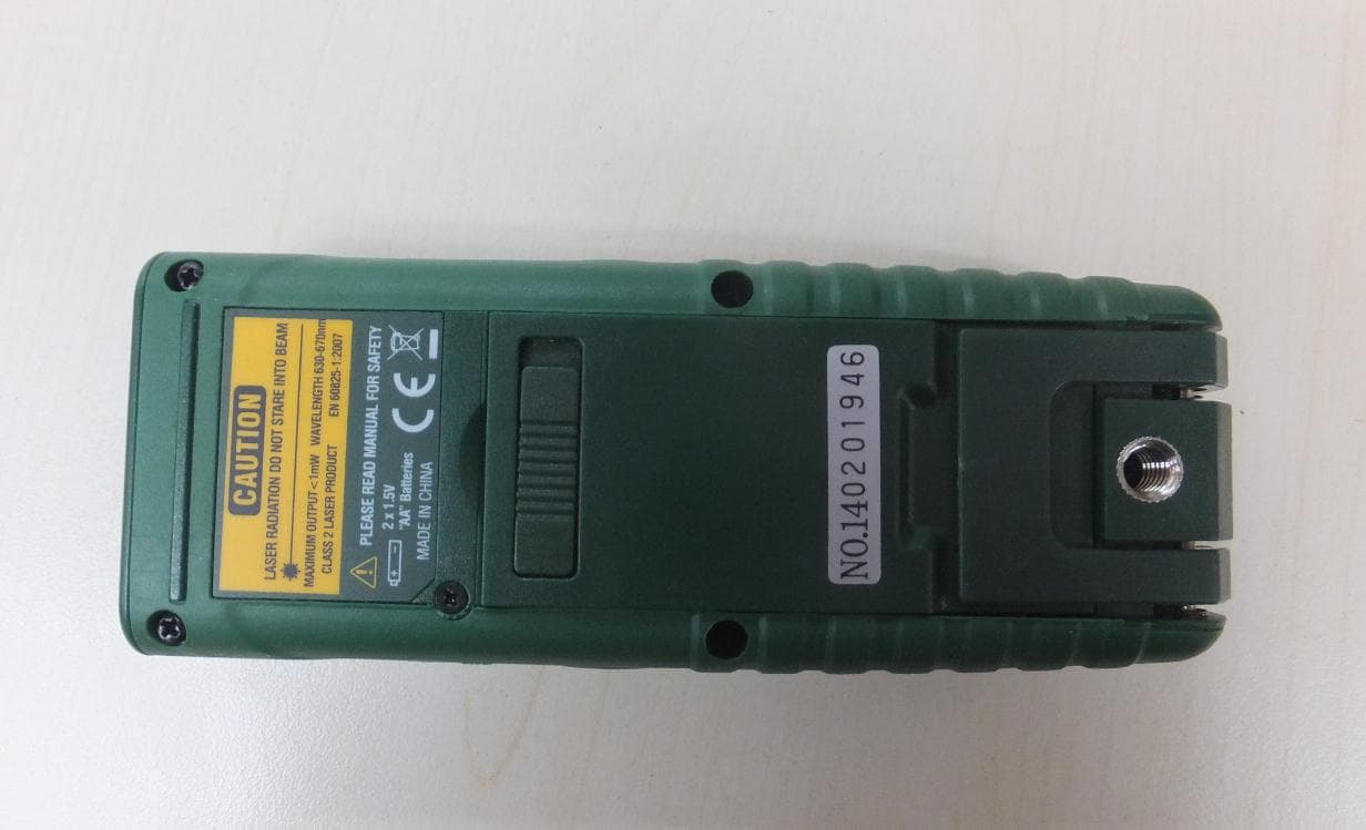
IWK-DT500
Jan 15, 2015Laser Distance Meter
Equipment Class
DSS - Part 15 Spread Spectrum Transmitter
IWK-GX900-GX930
Aug 17, 2014Multimeter with Bluetooth
Equipment Class
DSS - Part 15 Spread Spectrum Transmitter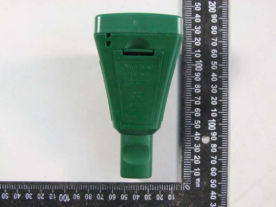
IWK-CG304
Jun 19, 2014Wireless Coating Thickness Tester
Equipment Class
DSS - Part 15 Spread Spectrum Transmitter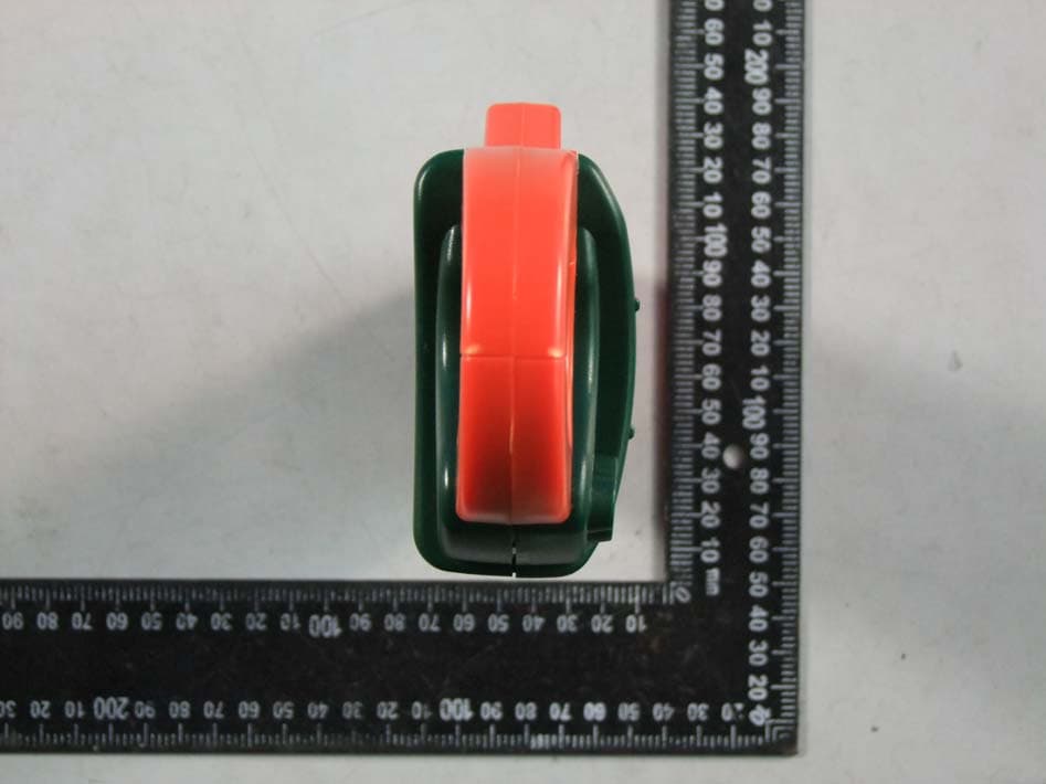
IWK-EX850
May 12, 2014Wireless Clamp Meter
Equipment Class
DSS - Part 15 Spread Spectrum Transmitter
IWK-MO270X
Feb 19, 2012Wireless Moisture Meter
Equipment Class
DXX - Part 15 Low Power Communication Device Transmitter