IWK-MG300Multimeter with wireless data transmitter
FLIR Commercial Systems, Inc.Application Details
- Equipment Class
- DXX - Part 15 Low Power Communication Device Transmitter
- Date of Grant
- Jan 18, 2012
- Application Purpose
- Original Equipment
- Date of Application
- Jan 17, 2012
- Equipment Note
- Multimeter with wireless data transmitter
- Frequency Range
- 915.00000000 - 915.00000000
- Country
- United States
Documents & Files
Document Text
Text extracted from the exhibit documents filed with the FCC. Open a document above to read the original.
Users Manual
User's Guide Wireless TRMS Multimeter and Insulation Tester Model MG300 2 MG300-EN V2.0 4/11 Introduction Congratulations on your purchase of the MG300 True RMS MultiMeter Insulation Resistance Tester. This meter measures AC/DC Voltage, AC/DC Current, Resistance, Capacitance, Frequency (electrical & electronic), Duty Cycle, Diode Test, Insulation Resistance, and Continuity plus Thermocouple Temperature. The MG300 can store and recall measurement data and features a waterproof, rugged design for heavy duty use. This meter can transmit data wirelessly when linked to a PC. Proper use and care of this meter will provide many years of reliable service. Safety This symbol adjacent to another symbol, terminal or operating device indicates that the operator must refer to an explanation in the Operating Instructions to avoid personal injury or damage to the meter. This WARNING symbol indicates a potentially hazardous situation, which if not avoided, could result in death or serious injury. This CAUTION symbol indicates a potentially hazardous situation, which if not avoided, may result damage to the product. This symbol advises the user that the terminal(s) so marked must not be connected to a circuit point at which the voltage with respect to earth ground exceeds (in this case) 1000 VAC or VDC. This symbol adjacent to one or more terminals identifies them as being associated with ranges that may, in normal use, be subjected to particularly hazardous voltages. For maximum safety, the meter and its test leads should not be handled when these terminals are energized. This symbol indicates that a device is protected throughout by double insulation or reinforced insulation. PER IEC1010 OVERVOLTAGE INSTALLATION CATEGORY OVERVOLTAGE CATEGORY I Equipment of OVERVOLTAGE CATEGORY I is equipment for connection to circuits in which measures are taken to limit the transient overvoltages to an appropriate low level. Note – Examples include protected electronic circuits. OVERVOLTAGE CATEGORY II Equipment of OVERVOLTAGE CATEGORY II is energy-consuming equipment to be supplied from the fixed installation. Note – Examples include household, office, and laboratory appliances. OVERVOLTAGE CATEGORY III Equipment of OVERVOLTAGE CATEGORY III is equipment in fixed installations. Note – Examples include switches in the fixed installation and some equipment for industrial use with permanent connection to the fixed installation. OVERVOLTAGE CATEGORY IV Equipment of OVERVOLTAGE CATEGORY IV is for use at the origin of the installation. Note – Examples include electricity meters and primary over-current protection equipment WARNING CAUTION MAX 1000V 3 MG300-EN V2.0 4/11 SAFETY INSTRUCTIONS This meter has been designed for safe use, but must be operated with caution. The rules listed below must be carefully followed for safe operation. 1. NEVER apply voltage or current to the meter that exceeds the specified maximum: Input Protection Limits Function Maximum Input V DC or V AC 1000VDC/AC rms mA AC/DC 500mA 1000V fast acting fuse A AC/DC 10A 1000V fast acting fuse (20A for 30 seconds max every 15 minutes) Frequency, Resistance, Capacitance, Duty Cycle, Diode Test, Continuity 1000VDC/AC rms Temperature 1000VDC/AC rms Surge Protection: 8kV peak per IEC 61010 2. USE EXTREME CAUTION when working with high voltages. 3. DO NOT measure voltage if the voltage on the "COM" input jack exceeds 1000V above earth ground. 4. NEVER connect the meter leads across a voltage source while the function switch is in the current, resistance, or diode mode. Doing so can damage the meter. 5. ALWAYS discharge filter capacitors in power supplies and disconnect the power when making resistance or diode tests. 6. ALWAYS turn off the power and disconnect the test leads before opening the covers to replace the fuse or batteries. 7. NEVER operate the meter unless the back cover and the battery and fuse covers are in place and fastened securely. 8. If the equipment is used in a manner not specified by the manufacturer, the protection provided by the equipment may be impaired. 4 MG300-EN V2.0 4/11 Controls and Jacks 1. 40,000 count LCD display 2. MAX/MIN ( - ) button 3. STORE (<RECALL) button 4. RANGE(SETUP) button 5. INSULATION TEST button 6. MODE button 7. Function switch 8. 10A input jack 9. mA, μA, Insulation (-) jack 10. HOLD (PEAKHOLD>) button 11. REL (+) button 12. EXIT (AC+DC) button 13. Backlight button 14. Positive and Insulation (+) input jack 15. COM input jack Note: Tilt stand and battery compartment are on rear of unit. Symbols and Annunciators •))) Continuity Diode test Battery status n nano (10 -9 ) (capacitance) μ micro (10 -6 ) (amps, cap) m milli (10 -3 ) (volts, amps) A Amps k kilo (10 3 ) (ohms) F Farads (capacitance) M mega (10 6 ) (ohms) RF transmitter active Ω Ohms PEAK Peak Hold Hz Hertz (frequency) V Volts % Percent (duty ratio) Relative AC Alternating current AUTO Autoranging DC Direct current HOLD Display hold ºF Degrees Fahrenheit ºC Degrees Celsius MAX Maximum MIN Minimum No. Serial number S second SET Setup parameter AC +DC Alternating current + Direct current TRMS True RMS STO Store RCL Recall AUTO Auto Range Auto Power off enabled Backlight Auxiliary Displays 1 8 7 6 5 2 3 4 9 10 11 12 13 14 15 5 MG300-EN V2.0 4/11 Operating Instructions WARNING: Risk of electrocution. High-voltage circuits, both AC and DC, are very dangerous and should be measured with great care. 1. ALWAYS turn the function switch to the OFF position when the meter is not in use. 2. If “OL” appears in the display during a measurement, the value exceeds the range you have selected. Change to a higher range. DC VOLTAGE MEASUREMENTS CAUTION: Do not measure DC voltages if a motor on the circuit is being switched ON or OFF. Large voltage surges may occur that can damage the meter. 1. Set the function switch to the VDC position. 2. Insert the black test lead banana plug into the negative COM jack. Insert the red test lead banana plug into the positive V jack. 3. To…
Text truncated - open the document above for the full version.
Test Report
FCC TEST REPORT For Wireless TRMS Multimeter and Insulation Test Model Number: MG300 FCC ID: IWK-MG300 Report Number : WT118002269 Test Laboratory : Shenzhen Academy of Metrology and Quality Inspection National Testing Center for Digital Electronic Products Site Location : Bldg. Metrology and Quality Inspection, Longzhu Road, Shenzhen, Guangdong, China Tel : 0086-755-26941599 Fax : 0086-755-26941545 Web : www.smq.com.cn Report No.: WT118002269 Page 2/18 Test report declaration Applicant : Extech Instruments Corporation Address : 9 Townsend West Nashua, NH 03063, USA Manufacturer : SHENZHEN EVERBEST MACHINERY INDUSTRY CO., LTD Address : 19 th Building, 5 th Region, Baiwangxin Industrial Park, Songbai Rd., Xili, Nanshan, Shenzhen, China Factory : SHENZHEN EVERBEST MACHINERY INDUSTRY CO., LTD Address : 19 th Building, 5 th Region, Baiwangxin Industrial Park, Songbai Rd., Xili, Nanshan, Shenzhen, China EUT Description : Wireless TRMS Multimeter and Insulation Test Model No : MG300 FCC ID : IWK-MG300 Test Standards: FCC Part 15 15.249 The EUT described above is tested by Shenzhen Academy of Metrology and Quality Inspection EMC Laboratory to determine the maximum emissions from the EUT. Shenzhen Academy of Metrology and Quality Inspection EMC Laboratory is assumed full responsibility for the accuracy of the test results. The test data, data evaluation, test procedures, and equipment configurations shown in this report were made in accordance with the procedures given in ANSI C63.4 (2003) and the energy emitted by the sample EUT tested as described in this report is in compliance with FCC Rules Part 15.249. The test report is valid for above tested sample only and shall not be reproduced in part without written approval of the laboratory. Project Engineer: Date: Dec.16,2011 (Ryan Chen) Dec.16,2011 Checked by: Date: (Dewelly Yang) Dec.16,2011 Approved by: Date: (Peter Lin) Report No.: WT118002269 Page 3/18 TABLE OF CONTENTS TEST REPORT DECLARATION ........................................................................................................ 2 1. TEST RESULTS SUMMARY ................................................................................................... 5 2. GENERAL INFORMATION ...................................................................................................... 6 2.1. Report information .......................................................................................................... 6 2.2. Laboratory Accreditation and Relationship to Customer ......................................... 6 2.3. Measurement Uncertainty ............................................................................................. 7 3. PRODUCT DESCRIPTION ...................................................................................................... 8 3.1. EUT Description .............................................................................................................. 8 3.2. Related Submittal(s) / Grant (s) ................................................................................... 8 3.3. Block Diagram of EUT Configuration .......................................................................... 8 3.4. Operating Condition of EUT.......................................................................................... 8 3.5. Special Accessories ....................................................................................................... 9 3.6. Equipment Modifications ............................................................................................... 9 3.7. Support Equipment List ................................................................................................. 9 3.8. Test Conditions ............................................................................................................... 9 4. TEST EQUIPMENT USED ..................................................................................................... 10 5. CONDUCTED DISTURBANCE TEST .................................................................................. 11 5.1. Test Standard and Limit .............................................................................................. 11 5.2. Test Procedure ............................................................................................................. 11 5.3. Test Arrangement ......................................................................................................... 11 5.4. Test Data ....................................................................................................................... 11 6. RADIATED DISTURBANCE TEST ....................................................................................... 12 6.1. Test Standard and Limit .............................................................................................. 12 6.2. Test Procedure ............................................................................................................. 12 6.3. Test Arrangement ......................................................................................................... 13 6.4. Test Data ....................................................................................................................... 13 7. OCCUPIED BANDWIDTH ...................................................................................................... 15 7.1. Test Standard and Limit .............................................................................................. 15 7.2. Test Procedure ............................................................................................................. 15 Report No.: WT118002269 Page 4/18 7.3. Test Arrangement ......................................................................................................... 15 7.4. Test Data ....................................................................................................................... 15 8. BAND EDGE ..............................…
Text truncated - open the document above for the full version.
Test Report
FCC TEST REPORT For Wireless TRMS Multimeter and Insulation Test Model Number: MG300 FCC ID: IWK-MG300 Report Number : WT148000350 Test Laboratory : Shenzhen Academy of Metrology and Quality Inspection National Digital Electronic Product Testing Center Site Location : No.4 TongFa Road, Xili Town, Nanshan District, Shenzhen, China Tel : 0086-755-86009898 Fax : 0086-755-86009898-31396 Web : www.smq.com.cn Report No.: WT148000350 Page 2/18 Test report declaration Applicant : Extech Instruments Corporation Address : 9 Townsend West Nashua, NH 03063, USA Manufacturer : SHENZHEN EVERBEST MACHINERY INDUSTRY CO., LTD Address : 19 th Building, 5 th Region, Baiwangxin Industrial Park, Songbai Rd., Xili, Nanshan, Shenzhen, China Factory : SHENZHEN EVERBEST MACHINERY INDUSTRY CO., LTD Address : 19 th Building, 5 th Region, Baiwangxin Industrial Park, Songbai Rd., Xili, Nanshan, Shenzhen, China EUT Description : Wireless TRMS Multimeter and Insulation Test Model No : MG300 FCC ID : IWK-MG300 Test Standards: FCC Part 15 15.249 The EUT described above is tested by Shenzhen Academy of Metrology and Quality Inspection EMC Laboratory to determine the maximum emissions from the EUT. Shenzhen Academy of Metrology and Quality Inspection EMC Laboratory is assumed full responsibility for the accuracy of the test results. The test data, data evaluation, test procedures, and equipment configurations shown in this report were made in accordance with the procedures given in ANSI C63.4 (2003) and the energy emitted by the sample EUT tested as described in this report is in compliance with FCC Rules Part 15.249. The test report is valid for above tested sample only and shall not be reproduced in part without written approval of the laboratory. Project Engineer: Date: Feb.13,2014 (Ryan Chen) Feb.13,2014 Checked by: Date: (Dewelly Yang) Feb.13,2014 Approved by: Date: (Peter Lin) Report No.: WT148000350 Page 3/18 TABLE OF CONTENTS TEST REPORT DECLARATION ........................................................................................................ 2 1. TEST RESULTS SUMMARY ................................................................................................... 5 2. GENERAL INFORMATION ...................................................................................................... 6 2.1. Report information .......................................................................................................... 6 2.2. Laboratory Accreditation and Relationship to Customer ......................................... 6 2.3. Measurement Uncertainty ............................................................................................. 7 3. PRODUCT DESCRIPTION ...................................................................................................... 8 3.1. EUT Description .............................................................................................................. 8 3.2. Related Submittal(s) / Grant (s) ................................................................................... 8 3.3. Block Diagram of EUT Configuration .......................................................................... 8 3.4. Operating Condition of EUT.......................................................................................... 8 3.5. Special Accessories ....................................................................................................... 9 3.6. Equipment Modifications ............................................................................................... 9 3.7. Support Equipment List ................................................................................................. 9 3.8. Test Conditions ............................................................................................................... 9 4. TEST EQUIPMENT USED ..................................................................................................... 10 5. CONDUCTED DISTURBANCE TEST .................................................................................. 11 5.1. Test Standard and Limit .............................................................................................. 11 5.2. Test Procedure ............................................................................................................. 11 5.3. Test Arrangement ......................................................................................................... 11 5.4. Test Data ....................................................................................................................... 11 6. RADIATED DISTURBANCE TEST ....................................................................................... 12 6.1. Test Standard and Limit .............................................................................................. 12 6.2. Test Procedure ............................................................................................................. 12 6.3. Test Arrangement ......................................................................................................... 13 6.4. Test Data ....................................................................................................................... 13 7. OCCUPIED BANDWIDTH ...................................................................................................... 15 7.1. Test Standard and Limit .............................................................................................. 15 7.2. Test Procedure ............................................................................................................. 15 Report No.: WT148000350 Page 4/18 7.3. Test Arrangement ......................................................................................................... 15 7.4. Test Data ....................................................................................................................... 15 8. BAND EDGE ...............................................…
Text truncated - open the document above for the full version.
Test Setup Photos
Radiated Disturbance
Contact Information
Applicant
Mark Sultzbach(QA Administrator)
Test Firm
Shenzhen Academy of Metrology & Quality InspectionPeter Lin
Technical Specifications
| # | Rule Parts | Frequency Range | Power Output |
|---|---|---|---|
| 1 | 15C | 915 MHz - 915 MHz | - |
Other Applications from FLIR Commercial Systems, Inc.
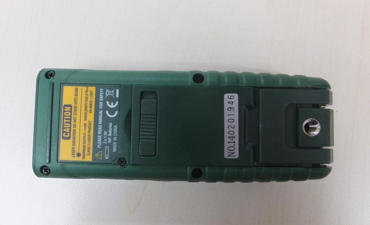
IWK-DT500
Jan 15, 2015Laser Distance Meter
Equipment Class
DSS - Part 15 Spread Spectrum Transmitter
IWK-GX900-GX930
Aug 17, 2014Multimeter with Bluetooth
Equipment Class
DSS - Part 15 Spread Spectrum Transmitter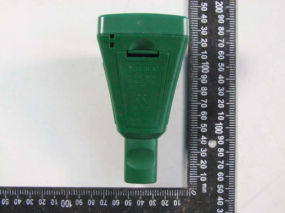
IWK-CG304
Jun 19, 2014Wireless Coating Thickness Tester
Equipment Class
DSS - Part 15 Spread Spectrum Transmitter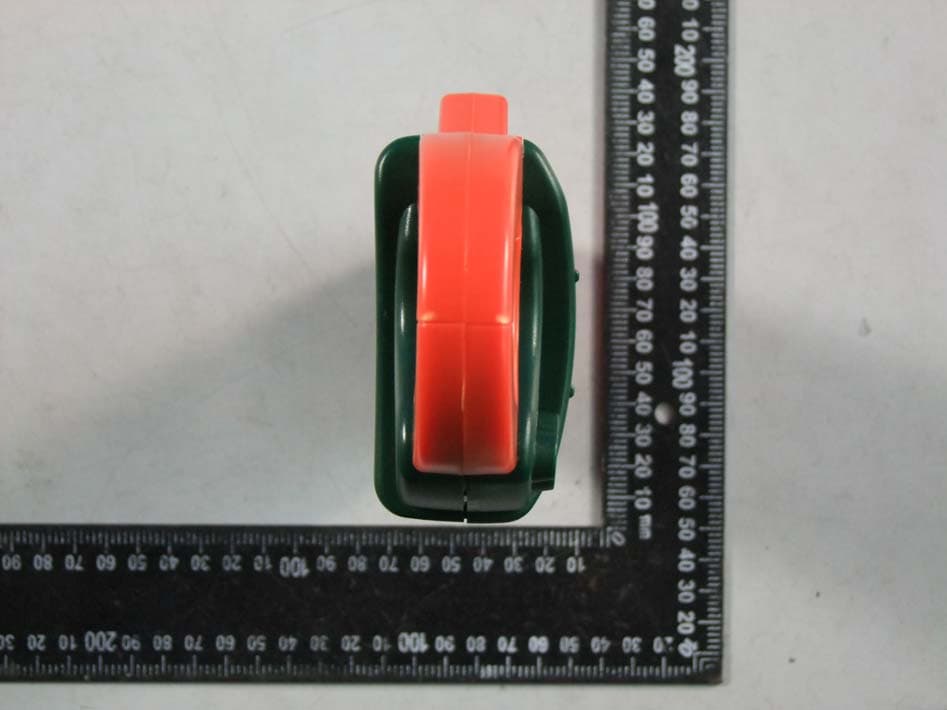
IWK-EX850
May 12, 2014Wireless Clamp Meter
Equipment Class
DSS - Part 15 Spread Spectrum Transmitter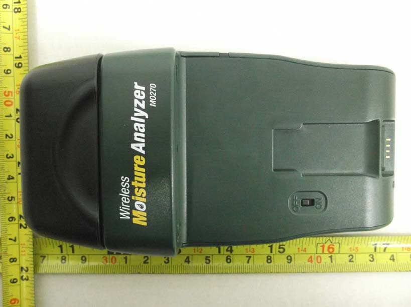
IWK-MO270X
Feb 19, 2012Wireless Moisture Meter
Equipment Class
DXX - Part 15 Low Power Communication Device Transmitter