IWK-MO297Bluetooth pinless Moisture/Humidity Meter + IR
FLIR Commercial Systems, Inc.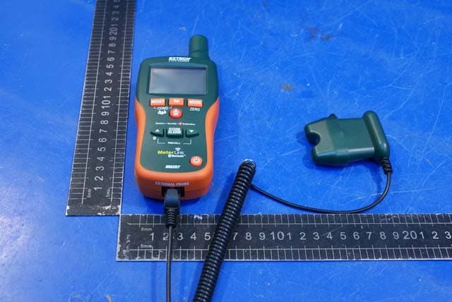
Click to zoom
Application Details
- Equipment Class
- DSS - Part 15 Spread Spectrum Transmitter
- Date of Grant
- Apr 14, 2010
- Application Purpose
- Original Equipment
- Date of Application
- Apr 14, 2010
- Equipment Note
- Bluetooth pinless Moisture/Humidity Meter + IR
- Frequency Range
- 2402.00000000 - 2480.00000000
- Country
- United States
Documents & Files
Document Text
Text extracted from the exhibit documents filed with the FCC. Open a document above to read the original.
Users Manual
User's Guide Bluetooth pinless Moisture/Humidity Meter + IR Model MO297 MO290 V3.0 03/09 2 Introduction Congratulations on your purchase of the Extech MO295 Bluetooth pinless Moisture Meter with Patented Built-in IR Thermometer. Monitor moisture in wood and other building materials with no surface damage with the Pinless Moisture sensor (Pin-type Moisture Probe included). Measure Humidity and Air Temperature with built-in probe plus non-contact InfraRed Temperature with patented IR design, Bluetooth data transmission. Advanced functions provide Grains per Pound, Dew Point and Vapor Pressure calculations. This meter is shipped fully tested and calibrated and, with proper use, will provide years of reliable service. Meter Description 1. IR temperature sensor 2. Laser pointer 3. Humidity sensor 4. Temperature sensor 5. LCD display 6. Relative Humidity button 7. Mode/Zero Button 8. IR thermometer button 9. Alarm set button 10. Alarm adjust down/Store trigger button 11. ON/OFF power button 12. Remote pin probe input jack (bottom) 13. Battery compartment (rear) 14. Alarm adjust up/BT active button 15. Moisture/Relative button 16. Protective cap LCD Display 1. MIN MAX – Minimum and maximum value 2. HIGH LOW – Alarm limits 3. INT EXT – Internal/External probe 4. mBar – Vapor pressure 5. kPa – Vapor pressure 6. GPP – Grains per Pound 7. g/kg – Grains per kilogram 8. MOIST – Moisture mode 9. RH% - Relative Humidity mode 10. COND – Condensation mode 11. APO – Auto power off 12. DEW – Dew Point temperature 13. C/F – Temperature units 14. - Low battery 15. - Laser pointer On 16. BT active Safety • Use extreme caution when the laser pointer beam is on • Do not point the beam toward anyone's eye or allow the beam to strike the eye from a reflective surface • Do not use the laser near explosive gases or in other potentially explosive areas 1 2 3 4 5 6 7 8 9 10 11 12 13 14 15 16 MO290 V3.0 03/09 3 Features • Quickly indicates the moisture content of materials with Pinless technology without damaging the surface; • Optional remote Pin-type probe (MO290-P) allows for moisture readings at different penetration levels (3ft/0.9m cable length); • Easy to read, large dual display with backlit feature; • Simultaneously displays % moisture of wood or material being tested and Air Temperature, IR Temperature, or Humidity • Designed with patented IR design to measure non-contact surface temperature; 8:1 distance to spot ratio with 0.95 fixed emissivity • Built-in Humidity/Temperature probe measures Relative Humidity, • Air Temperature plus Grains Per Pound (GPP) and Dew Point (DP) • Automatic calculation of differential Temperature (IR - DP) • Min/Max and Data Hold • Auto power off and low battery indication • Memory function Battery Replacement 1. Turn off the meter. 2. Remove one Philips head screw and lift off the rear battery cover. 3. Replace the 9V battery. 4. Secure the rear battery cover. MO290 V3.0 03/09 4 Operation Powering the meter 1. Remove the RH sensor protective cap before use. 2. Press the power button to turn the meter on. 3. If the symbol appears or the meter does not turn on, replace the battery. Humidity (Dew point, GPP, g/kg) Measurements 1. Press the power button to turn the meter on. 2. Press the RH button 3. Relative Humidity will be displayed in the primary display and the temperature will be displayed in the secondary display. 4. Press the up or down arrow button to change the temperature units. 5. Press the MODE button to display the DEW point. 6. Press the MODE button to display GPP (°F) or g/kg (°C) Pinless Moisture Measurements 1. Press the power button to turn the meter on. 2. Press the MOIST button to select Moisture measurement.” MOIST”,”REL” and “INT” (internal pinless sensor) will appear in the display. 3. Hold the meter so that the rear sensor is away from any surface or your hand. The reading should be near 0.0. If not, press and hold the ZERO button for more than 2 second and the ZERO icon appears. 4. Place the rear sensor on the surface of the material to be tested and read the relative moisture content. Pin Type Moisture Measurements 1. Connect the external pin probe to the jack on the bottom of the meter. 2. Press the power button to turn the meter on. 3. Press the MOIST button twice to select Moisture measurement.” MOIST”, “%” and “EXT” (external pin probe) will appear in the display. 4. Press the probe pins into the material and read the % moisture content in the display. MO290 V3.0 03/09 5 Infrared Temperature Measurements 1. Press the power button to turn the meter on. 2. Press the IRT button to enable the IR thermometer and the laser pointer. The laser pointer icon will flash while the mode is active. 3. Press the up or down arrow button to change the temperature units 4. Aim the laser pointer at the surface to be measured and read the surface temperature in the secondary display. 5. Release the IRT button. The last temperature measured and the laser icon will remain on the display for approximately 10 seconds before returning to ambient temperature measurement. IRT MAX MIN display: The meter can be set to display only the maximum or minimum temperature measured during an IR scan. 1. With the meter in the IR hold mode, press the MODE button. “MIN” will appear in the display. 2. Press the IRT button to enable the IR thermometer. The meter will display the minimum temperature measured and will update only when a lower temperature is measured. 3. Press the MODE button twice to enable the MAX mode and proceed as stated above for the maximum temperature. 4. The MAX or MIN temperature is not stored when the function is exited. IR Field of View Ensure that the desired target is larger than the spot size. As the distance from an object increases, the spot size of the area measured by the meter becomes larger. The meter’s field of view ratio is 8:1, meaning that if the meter is 8 inches (cm) from the target, the diameter (spot) of the object under test must be at least 1 inch (…
Text truncated - open the document above for the full version.
Attestation Statements
Hopping Information 1. Hopping Range Hereby we declare that the maximum frequency of this device is: 2402-2480MHz. This is according the Bluetooth Core Specification V1.2 for devices which will be operated in the Europe. This was checked during the Bluetooth Qualification tests. Other frequency ranges (e.g. for USA, China, Japan) which are allowed according the Core Specification are not supported by this device. 2. Hopping Sequence Example of a 79 hopping sequence in data mode: 33,04,21,44,23,42,53,46,55,48,40,59,72,29,76,31,08,73, 07,75,09,45,60,39,58,13,47,11,77,52,35,50,65,54,67,56, 69,62,71,64, 37,25,27,66,57,70,74,61,78,63,10,41,05,43, 15,44,64,68,02,70,06,01,51,03,55,05,03,66,53,49,36,47. 3. Receiver input bandwidth The input bandwidth of the receiver is 1MHz. In every connection one Bluetooth device is the master and the other one is the slave. The master determines the hopping sequence. The slave follows this sequence. Both devices shift between RX and TX time slot according to the clock of the master. Additionally the type of connection is set up at the beginning of the connection. The master adapts its hopping frequency and its TX/RX timing according to the packet type of the connection. Also the slave of the connection will use these settings. Repeating of a packer has no influence on the hopping sequence. The hopping sequence generated by the master of the connection will be followed in any case. That means a repeated packet will not be send on the same frequency, it is send on the next frequency of the hopping sequence.
External Photos
Page 1/2 Report No.:WT108000074 Page 1 of 2 APPENDIX II EUT Photo Page 2/ Report No.:WT108000074 Page 2 of 2 Photo 1 Appearance of EUT Photo 2 Appearance of EUT
Internal Photos
Page 1/4 Report No.:WT108000074 Page 1 of 4 APPENDIX III EUT Photo Page 2/ Report No.:WT108000074 Page 2 of 4 Photo 1 Inside of EUT (with RF module) Photo 2 Inside of EUT (with RF module) Page 3/ Report No.:WT108000074 Page 3 of 4 Photo 3 Inside of EUT Photo 4 Bluetooth Module (top) Antenna Page 4/ Report No.:WT108000074 Page 4 of 4 Photo 5 Bluetooth Module (bottom)
Test Report
Page 1/65 FCC TEST REPORT For Bluetooth pinless Moisture/Humidity Meter + IR Model Number: MO297 FCC ID: IWK- MO297 Report Number: WT108000576 Test Laboratory : Shenzhen Academy of Metrology and Quality Inspection National Testing Center for Digital Electronic Products Site Location : Bldg. Metrology and Quality Inspection, Longzhu Road, Shenzhen, Guangdong, China Tel : 0086-755-26941599 Fax : 0086-755-26941545 Web : www.smq.com.cn Report No.:WT108000576 Page 2 of 65 Test report declaration Applicant : Extech Instruments Corporation Address : 285 Bear Hill Road Waltham, MA 02451, USA Manufacturer : SHENZHEN EVERBEST MACHINERY INDUSTRY CO.,LTD. Address : 19th Building, 5th Region, Baiwangxin Industrial Park, Songbai Rd., Baimang, Xili,Nanshan, Shenzhen, China EUT Description : Bluetooth pinless Moisture/Humidity Meter + IR Model No : MO297 Trade mark : EXTECH Serial Number : (No) FCC ID : IWK- MO297 Test Standards: FCC Part 15, Subpart C, §15.247 The EUT described above is tested by Shenzhen Academy of Metrology and Quality Inspection EMC Laboratory to determine the maximum emissions from the EUT. Shenzhen Academy of Metrology and Quality Inspection EMC Laboratory is assumed full responsibility for the accuracy of the test results. The test data, data evaluation, test procedures, and equipment configurations shown in this report were made in accordance with the procedures given in ANSI C63.4 (2003) and the energy emitted by the sample EUT tested as described in this report is in compliance with FCC Rules §15.109, §15.203, §15.205, §15.209 and §15.247. The test report is valid for above tested sample only and shall not be reproduced in part without written approval of the laboratory. Project Engineer: Date: April 8, 2010 (Bill Yi) Checked by: Date: April 8, 2010 (Ryan Chen) Approved by: Date: April 8, 2010 (Peter Lin) Report No.:WT108000576 Page 3 of 65 TABLE OF CONTENTS TEST REPORT DECLARATION........................................................................................................2 1. SUMMARY OF TEST RESULTS............................................................................................5 2. GENERAL INFORMATION......................................................................................................6 2.1. Report information..........................................................................................................6 2.2. Laboratory Accreditation and Relationship to Customer.........................................6 2.3. Measurement Uncertainty.............................................................................................7 3. PRODUCT DESCRIPTION......................................................................................................8 3.1. EUT Description..............................................................................................................8 3.2. Related Submittal(s) / Grant (s)...................................................................................8 3.3. Block Diagram of EUT Configuration..........................................................................9 3.4. Operating Condition of EUT..........................................................................................9 3.5. Support Equipment List.................................................................................................9 3.6. Test Conditions...............................................................................................................9 3.7. Special Accessories.......................................................................................................9 3.8. Equipment Modifications.............................................................................................10 3.9. Test Methodology.........................................................................................................10 4. TEST EQUIPMENT USED.....................................................................................................11 5. RF EXPOSURE........................................................................................................................12 5.1. Test Standard and Limit..............................................................................................12 5.2. Test Data.......................................................................................................................12 6. ANTENNA REQUIREMENT...................................................................................................14 6.1. Test Standard and Limit..............................................................................................14 6.2. Result.............................................................................................................................14 7. RADIATED SPURIOUS EMISSIONS TEST.......................................................................15 7.1. Test Standard and Limit..............................................................................................15 7.2. Test Procedure.............................................................................................................15 7.3. Test Arrangement.........................................................................................................16 7.4. Test Data.......................................................................................................................17 8. CHANNEL SEPARATION.......................................................................................................32 Report No.:WT108000576 Page 4 of 65 8.1. Test Standard and Limit..............................................................................................32 8.2. Test Procedure.............................................................................................................32 8.3. Test Data.......................................................................................................................32 9. 20DB BAND…
Text truncated - open the document above for the full version.
Test Setup Photos
Page 1/3 Report No.:WT108000074 Page 1 of 3 APPENDIX I TEST PHOTOS Page 2/ Report No.:WT108000074 Page 2 of 3 Photo 1 Front of Radiated Disturbance Test, Measuring Mode Photo 2 Rear of Radiated Disturbance Test, Measuring Mode Page 3/ Report No.:WT108000074 Page 3 of 3 Photo 3 Front of Radiated Disturbance Test (Above 1GHz) Photo 4 Rear of Radiated Disturbance Test (Above 1GHz)
Contact Information
Applicant
Mark Sultzbach(QA Administrator)
Test Firm
Shenzhen Academy of Metrology & Quality InspectionPeter Lin
Technical Specifications
| # | Rule Parts | Frequency Range | Power Output |
|---|---|---|---|
| 1 | 15C | 2.40 GHz - 2.48 GHz | 490.00 µW |
Other Applications from FLIR Commercial Systems, Inc.
IWK-DT500
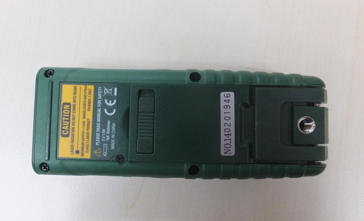
Jan 15, 2015Laser Distance Meter
Equipment Class
DSS - Part 15 Spread Spectrum Transmitter
IWK-GX900-GX930
Aug 17, 2014Multimeter with Bluetooth
Equipment Class
DSS - Part 15 Spread Spectrum Transmitter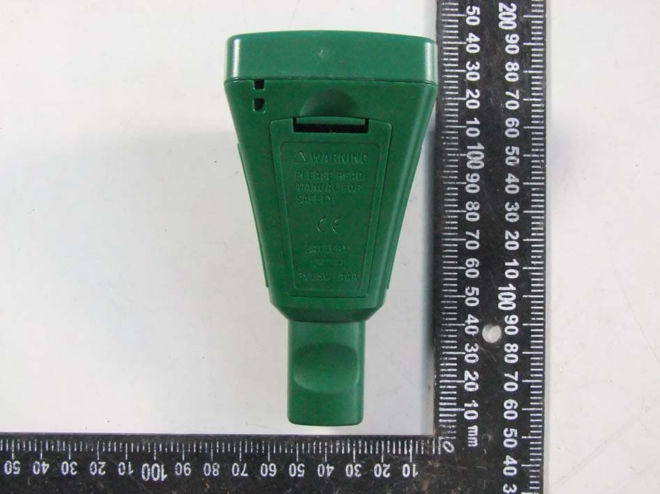
IWK-CG304
Jun 19, 2014Wireless Coating Thickness Tester
Equipment Class
DSS - Part 15 Spread Spectrum Transmitter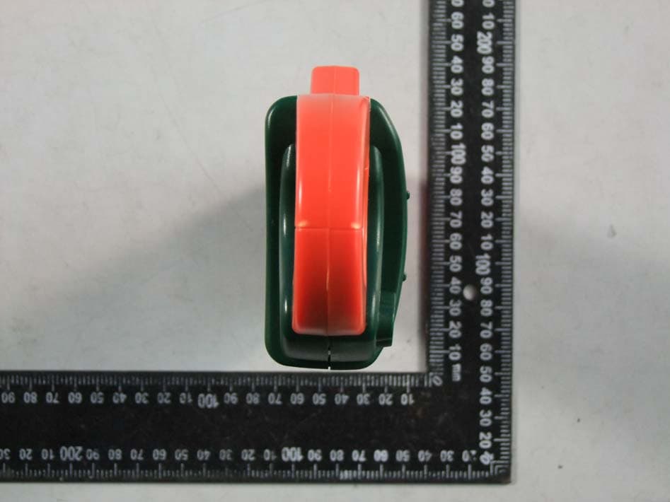
IWK-EX850
May 12, 2014Wireless Clamp Meter
Equipment Class
DSS - Part 15 Spread Spectrum Transmitter
IWK-MO270X
Feb 19, 2012Wireless Moisture Meter
Equipment Class
DXX - Part 15 Low Power Communication Device Transmitter