IXVTX4313RSRemote Control
Automicro Technology Inc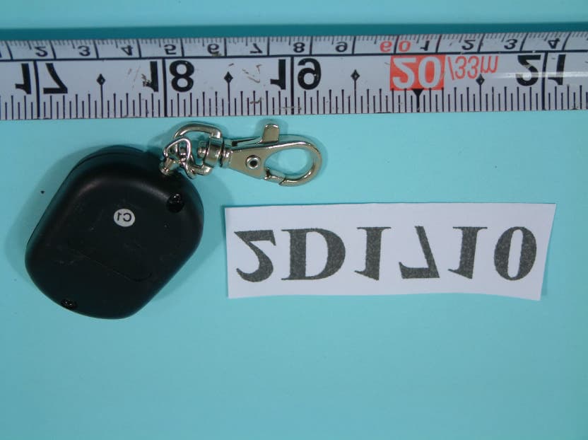
Click to zoom
Application Details
- Equipment Class
- DSC - Part 15 Security/Remote Control Transmitter
- Date of Grant
- Feb 02, 2003
- Application Purpose
- Original Equipment
- Date of Application
- Feb 02, 2003
- Equipment Note
- Remote Control
- Frequency Range
- 433.92000000 - 433.92000000
- Company
- Automicro Technology Inc
- Country
- Taiwan
Documents & Files
Document Text
Text extracted from the exhibit documents filed with the FCC. Open a document above to read the original.
Users Manual
Telephonic Car Alarm & Remote Starter User’s Manual New Generation Technology - The Telephonic Car Alarm & Remote Starter - www.ngtwindsor.com 1 Table of Contents 1.0 Overview.......................................................................................................................................................................... 2 2.0 Remote Control Functions: .............................................................................................................................................. 2 3.0 Remote Control Functions for System Programming ....................................................................................................... 2 3.1 Vibration Test Mode................................................................................................................................................. 2 3.2Phone Number/Remote Programming Mode............................................................................................................. 2 4.0 PassiveAlarm Function ................................................................................................................................................... 3 5.0 GUNALARM FUNCTION (Optional)................................................................................................................................. 3 6.0AUTOMATIC VIBRATION SENSOR ®............................................................................................................................. 3 7.0 GREENALARM SYSTEM............................................................................................................................................... 3 8.0 TWO LEVELTELEPHONE NOTIFICATION..................................................................................................................... 4 7.0 USING THE THIRD BUTTON FOR MULTI USERS........................................................................................................... 4 8.0 TURNING ON THE ENGINE VIA TELEPHONE................................................................................................................ 4 9.0 REMOTE CONTROL BY TELEPHONE........................................................................................................................... 4 9.1 Instruction-programming:......................................................................................................................................... 4 9.2 The 9 instructions after the beep: ............................................................................................................................ 4 10.0 MONITOR LED.............................................................................................................................................................. 5 11.0 PROGRAMMING THE CAR-ALARM TELEPHONE........................................................................................................ 6 Telephonic Car Alarm & Remote Starter User’s Manual New Generation Technology - The Telephonic Car Alarm & Remote Starter - www.ngtwindsor.com 2 1.0 Overview The Telephonic CarAlarm and Remote Starter is a newly developed alarm system under a patent protection. The alarm system consists of 5 components: 1. Central control processing unit (GRA 02) 2. Cell phone in a protective box (W.COM 02) 3. Remote control (R.C. 402) 4. Immobilizer relays 5. SS 02 Shock Sensor 2.0 Remote Control Functions: • Pressing button # 1 once: turns alarm on and uploads the first user’s telephone number into memory (in case of alarm, the notification goes out to this number) (note: once this is pressed, buttons#2or#3 can’t be pressed, since they have become inactive.) Only by turning the alarm off (press button # 4) will the user be able to switch to button#2or#3. • Pressing button # 2 once: turns alarm on and uploads the second user’s telephone number into memory. (Note: same as previously noted) • Pressing button # 3 once: turns alarm on and uploads the third user’s telephone number into memory. (Note: same as previously noted) • Pressing button # 4 once: deactivates alarm • Holding button # 1 down continuously (at least for 1.5 seconds): activates PANICALARM (horn (siren) + lights) 3.0 Remote Control Functions for System Programming • Pressing button # 2 for 4 to 7 seconds: enables the following system modes: 3.1 Vibration Test Mode “VIBRATION TEST” FUNCTION is activated for 2 minutes. In this mode a test and check can be done on the proper operation of the vibration sensors’ optimal sensitivity, without having to use the automatic self-adjusting system. The adjustment is accurate when by tapping on the windshield or on the roof the MONITOR LED turns on for about 5 seconds, then turns off. Upon repeated tapping it turns on. This way a can a test can be conducted on the car as to its sensitivity at various spots. This function is automatically cancelled in 2 minutes. 3.2Phone Number/Remote Programming Mode PROGRAMMING THE TELEPHONE: we have the same 2 minutes to assign the preprogrammed telephone numbers to the remote control, that’s the only way for the alarm system to call the driver. The precise sequence of PROGRAMMING is available in Section 10.0 “PROGRAMMING THE TELEPHONE”. Telephonic Car Alarm & Remote Starter User’s Manual New Generation Technology - The Telephonic Car Alarm & Remote Starter - www.ngtwindsor.com 3 4.0 Passive Alarm Function Once the alarm is deactivated (the MONITOR LED is not lit) the engine must be started within one minute If you don’t start the engine within 1 minute, the central processing unit switches to the Passive Alarm mode. The PassiveAlarm Function is a security feature that automatically activates the alarm and vehicle immobilizer when your vehicle is left unarmed for more than 60 seconds When the Passive Alarm function is active the MONITOR LED is brightly lit. In this case the engine can only re started if the alarm is turned on with one of the “ON” buttons, and then turned OFF in 2-3…
Text truncated - open the document above for the full version.
External Photos
FCC ID : IXVTX4313RS Number 1 FRONT SIDE OF EUT (FOR FOUR BUTTON) FCC ID : IXVTX4313RS Number 2 REAR SIDE OF EUT (FOR FOUR BUTTON) FCC ID : IXVTX4313RS Number 3 FRONT SIDE OF EUT (FOR THREE BUTTON) FCC ID : IXVTX4313RS Number 4 REAR SIDE OF EUT (FOR THREE BUTTON) FCC ID : IXVTX4313RS Number 5 FRONT SIDE OF EUT (FOR TWO BUTTON) FCC ID : IXVTX4313RS Number 6 REAR SIDE OF EUT (FOR TWO BUTTON) FCC ID : IXVTX4313RS Number 7 FRONT SIDE OF EUT (FOR ONE BUTTON) FCC ID : IXVTX4313RS Number 8 REAR SIDE OF EUT (FOR ONE BUTTON)
ID Label/Location Info
0.33mm 2cm FCC ID:IXVTX4313RS FCC ID: IXVTX4313RS
Internal Photos
FCC ID : IXVTX4313RS Number 1 MECHANICAL CONSTRUCTION (FOR FOUR BUTTON) FCC ID : IXVTX4313RS Number 2 MECHANICAL CONSTRUCTION (FOR FOUR BUTTON) FCC ID : IXVTX4313RS Number 3 FRONT SIDE OF MAIN BOARD (FOR FOUR BUTTON) FCC ID : IXVTX4313RS Number 4 REAR SIDE OF MAIN BOARD (FOR FOUR BUTTON) FCC ID : IXVTX4313RS Number 5 MECHANICAL CONSTRUCTION (FOR THREE BUTTON) FCC ID : IXVTX4313RS Number 6 MECHANICAL CONSTRUCTION (FOR THREE BUTTON) FCC ID : IXVTX4313RS Number 7 FRONT SIDE OF MAIN BOARD (FOR THREE BUTTON) FCC ID : IXVTX4313RS Number 8 REAR SIDE OF MAIN BOARD (FOR THREE BUTTON) FCC ID : IXVTX4313RS Number 9 MECHANICAL CONSTRUCTION (FOR TWO BUTTON) FCC ID : IXVTX4313RS Number 10 MECHANICAL CONSTRUCTION (FOR TWO BUTTON) FCC ID : IXVTX4313RS Number 11 FRONT SIDE OF MAIN BOARD (FOR TWO BUTTON) FCC ID : IXVTX4313RS Number 12 REAR SIDE OF MAIN BOARD (FOR TWO BUTTON) FCC ID : IXVTX4313RS Number 13 MECHANICAL CONSTRUCTION (FOR ONE BUTTON) FCC ID : IXVTX4313RS Number 14 MECHANICAL CONSTRUCTION (FOR ONE BUTTON) FCC ID : IXVTX4313RS Number 15 FRONT SIDE OF MAIN BOARD (FOR ONE BUTTON) FCC ID : IXVTX4313RS Number 16 REAR SIDE OF MAIN BOARD (FOR ONE BUTTON)
Test Report
FCC TEST REPORT Report No. : F2D1710-01 SPORTON International Inc. TEL : 886-2-2696-2468 FAX : 886-2-2696-2255 FCC TEST REPORT for 47 CFR, Part 15, Subpart C Equipment : Remote Control Model No. : TX4313RS FCC ID : IXVTX4313RS Filing Type : Certification Applicant : AutoMicro TECHNOLOGY INC. No. 6, Alley 8, Lane 214, Pao-Ping Road, Young-Ho City, Taipei Hsien, Taiwan, R.O.C. † The test result refers exclusively to the test presented test model / sample. † Without written approval of SPORTON International Inc., the test report shall not be reproduced except in full. † Certificate or Test Report must not be used by the applicant to claim the product in this test report endorsement by NVLAP or any agency of U.S. government. SPORTON International Inc. 6F, No.106, Sec. 1, Hsin Tai Wu Rd., Hsi Chih, Taipei Hsien, Taiwan, R.O.C. FCC TEST REPORT Report No. : F2D1710-01 SPORTON International Inc. FCC ID : IXVTX4313RS TEL : 886-2-2696-2468 Page No. : i FAX : 886-2-2696-2255 Issued Date : Jan. 16, 2003 Table of Contents History of this test report.........................................................................................................................ii CERTIFICATE OF COMPLIANCE..............................................................................................................1 1. General Description of Equipment under Test......................................................................................2 1.1. Applicant.......................................................................................................................................................................................2 1.2. Manufacturer.................................................................................................................................................................................2 1.3. Basic Description of Equipment under Test..................................................................................................................................2 1.4. Feature of Equipment under Test.................................................................................................................................................2 2. Test Configuration of Equipment under Test........................................................................................3 2.1. Test Manner..................................................................................................................................................................................3 2.2. Description of Test System...........................................................................................................................................................3 2.3. Connection Diagram of Test System.............................................................................................................................................4 2.4. A plot shows the EUT meet the requirement of 15.231(c).............................................................................................................5 3. Test Software........................................................................................................................................6 4. General Information of Test..................................................................................................................7 4.1. Test Facility...................................................................................................................................................................................7 4.2. Test Voltage..................................................................................................................................................................................7 4.3. Standard for Methods of Measurement.........................................................................................................................................7 4.4. Test in Compliance with................................................................................................................................................................7 4.5. Frequency Range Investigated.....................................................................................................................................................7 4.6. Test Distance................................................................................................................................................................................7 5. Test of Conducted Powerline................................................................................................................8 6. Test of Radiated Emission....................................................................................................................9 6.1. Major Measuring Instruments........................................................................................................................................................9 6.2. Test Procedures..........................................................................................................................................................................10 6.3. Typical Test Setup Layout of Radiated Emission........................................................................................................................11 6.4. Test Result of Radiated Emission...............................................................................................................................................12 7. Antenna Factor & Cable Loss.............................................................................................................18 8. EMI Suppression Component List......................................................................................................19 9. List of Measuring Equipments Used...................................................................................................20 10. Uncertainty of Test Site..........…
Text truncated - open the document above for the full version.
Test Setup Photos
FCC TEST REPORT Report No. : F2D1710-01 SPORTON International Inc. FCC ID : IXVTX4313RS TEL : 886-2-2696-2468 Page No. : 1 of 1 FAX : 886-2-2696-2255 Issued Date : Jan. 16, 2003 p, 13, 2002 1.1. Photographs of Radiated Emission Test Configuration l The photographs show the configuration that generates the maximum emission. FRONT VIEW REAR VIEW
Contact Information
Applicant
Alice Hung(Manager)
Test Firm
SPORTON International IncKathy Lin
Technical Specifications
| # | Rule Parts | Frequency Range | Power Output |
|---|---|---|---|
| 1 | 15.231 | 433.92 MHz - 433.92 MHz | - |
Other Applications from Automicro Technology Inc

IXV-TX3314S
Mar 27, 2008REMOTE CONTROL (TRANSMITTER)
Equipment Class
DSC - Part 15 Security/Remote Control Transmitter
IXVTXF-4311R
Aug 06, 2007Remote Control
Equipment Class
DSC - Part 15 Security/Remote Control Transmitter
IXVTX3312S
Feb 25, 2004Remote Control TX3312S
Equipment Class
DSC - Part 15 Security/Remote Control Transmitter
IXVTX3316RS
Mar 11, 2003Remote Control Transmitter
Equipment Class
DSC - Part 15 Security/Remote Control Transmitter
IXVTA3312-1
Sep 15, 2002RF Remote Control
Equipment Class
DSC - Part 15 Security/Remote Control Transmitter