J2LRFHIFXLimited Modular Transmitter
FUJIFILM Business Innovation Corp.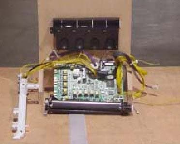
Click to zoom
Application Details
- Equipment Class
- DCD - Part 15 Low Power Transmitter Below 1705 kHz
- Date of Grant
- Apr 15, 2003
- Application Purpose
- Original Equipment
- Date of Application
- Apr 15, 2003
- Equipment Note
- Limited Modular Transmitter
- Frequency Range
- 0.12500000 - 0.12500000
- Country
- Japan
Documents & Files
Document Text
Text extracted from the exhibit documents filed with the FCC. Open a document above to read the original.
Users Manual
9 1.4 Installation Procedure 1 1.4.3Installing the EP Cartridge When installing the EP cartridge, take note of the following points: • Do not subject it to direct sunlight or strong light. • When installing the EP cartridge, select a location not subject to strong light and try to finish the installation within 5 minutes. • Do not touch the surface of the photosensitive drum. Do not stand or place the EP cartridge upside down. The drum might get damaged. • A drum shutter protects the photosensitive drum from light. Do not open the drum shutter. • Although the toner is not harmful to the body, wash it off immediately if your hands or clothes are stained with it. • It is recommended to use up the EP cartridge within 1 year after opening it. “5.2.2 Replacing the EP Cartridge” for details when replacing the EP cartridge. Open the top cover. Do not touch any parts inside the printer. Take the EP cartridge out of the box and shake it 7 to 8 times as shown in the diagram. Never throw an EP cartridge into an open flame. It can cause an explosion and you can get burnt. Jigen_IOT.book Page 9 Thursday, February 20, 2003 9:24 AM 10 1 1.4 Installation Procedure Place the EP cartridge on a flat surface and pull the seal out horizontally. • When pulling out the seal, pull it out horizontally. The tape might break if it is pulled out diagonally. • After the seal has been pulled out, do not shake or bump the EP cartridge. Hold the EP cartridge by the grip and insert it into the slot inside the printer. • Do not touch any parts inside the printer. • Ensure that the EP cartridge is firmly set. Close the top cover securely. Jigen_IOT.book Page 10 Thursday, February 20, 2003 9:24 AM 14 1 1.4 Installation Procedure 1.4.4Installing the Toner Cartridges Follow the procedure below to install the toner cartridges The toner is harmless but should still be washed off immediately if it comes into contact with hands or clothing. Remove the top cover. Select the new toner cartridge whose color matches the cartridge holder and remove it from its packaging. 15 1 1.4 Installation Procedure Shake the toner cartridge 7 or 8 times as shown in the illustration to distribute the toner evenly. Align the toner cartridge with the corre- sponding insertion point in the printer and insert it as shown in the illustration. Grip the levers at each end of the toner car- tridge with your fingers, then push down firmly to rotate the levers forward. 16 1 1.4 Installation Procedure Pull the toner seal straight up to remove it. Pull the toner seal straight up. Pulling the toner seal diago- nally may tear the seal. Repeat steps - to install the remaining toner cartridges. Replace the top cover.
Users Manual
9 1.4 Installation Procedure 1 1.4.3Installing the EP Cartridge When installing the EP cartridge, take note of the following points: • Do not subject it to direct sunlight or strong light. • When installing the EP cartridge, select a location not subject to strong light and try to finish the installation within 5 minutes. • Do not touch the surface of the photosensitive drum. Do not stand or place the EP cartridge upside down. The drum might get damaged. • A drum shutter protects the photosensitive drum from light. Do not open the drum shutter. • Although the toner is not harmful to the body, wash it off immediately if your hands or clothes are stained with it. • It is recommended to use up the EP cartridge within 1 year after opening it. “5.2.2 Replacing the EP Cartridge” for details when replacing the EP cartridge. Open the top cover. Do not touch any parts inside the printer. Take the EP cartridge out of the box and shake it 7 to 8 times as shown in the diagram. Never throw an EP cartridge into an open flame. It can cause an explosion and you can get burnt. Jigen_IOT.book Page 9 Thursday, February 20, 2003 9:24 AM 10 1 1.4 Installation Procedure Place the EP cartridge on a flat surface and pull the seal out horizontally. • When pulling out the seal, pull it out horizontally. The tape might break if it is pulled out diagonally. • After the seal has been pulled out, do not shake or bump the EP cartridge. Hold the EP cartridge by the grip and insert it into the slot inside the printer. • Do not touch any parts inside the printer. • Ensure that the EP cartridge is firmly set. Close the top cover securely. Jigen_IOT.book Page 10 Thursday, February 20, 2003 9:24 AM 14 1 1.4 Installation Procedure 1.4.4Installing the Toner Cartridges Follow the procedure below to install the toner cartridges The toner is harmless but should still be washed off immediately if it comes into contact with hands or clothing. Remove the top cover. Select the new toner cartridge whose color matches the cartridge holder and remove it from its packaging. 15 1 1.4 Installation Procedure Shake the toner cartridge 7 or 8 times as shown in the illustration to distribute the toner evenly. Align the toner cartridge with the corre- sponding insertion point in the printer and insert it as shown in the illustration. Grip the levers at each end of the toner car- tridge with your fingers, then push down firmly to rotate the levers forward. 16 1 1.4 Installation Procedure Pull the toner seal straight up to remove it. Pull the toner seal straight up. Pulling the toner seal diago- nally may tear the seal. Repeat steps - to install the remaining toner cartridges. Replace the top cover.
Cover Letter(s)
April 16, 2003 14085 Howard Rd Dayton, MD 21036 Federal Communications Commission 7435 Oakland Mills Road Columbia, MD 21036 Re: FCC ID:J2LRFHIFX Gentlemen: Submitted herewith is an application for a low frequency transmitter module to be used in a series of printers having essentially same form factor. In accordance with the requirements set forth in DA 00-1407 Released: June 26, 2000, this device incorporates the design features as described and listed below for Part 15 limited modular transmitter approval: 1. The modular transmitter has its own RF shielding. As can be seen from the test site photos, the device was tested outside the host equipment that provided data and power to the unit. This basic pc board is host to the RF transmitter circuit and is used across many printers comprising a family of products having the same basic mechanical and electrical specifications. 2. This modular transmitter only has data inputs from the basic printer and toner cartridge assembly thus ensuring that the module will continue to comply with Part 15 requirements and no conditions of excessive data rates or over-modulation can occur. 3. This modular transmitter receives its DC power from a regulated supply providing power to the main PC board. The design of the power supply circuitry in the printers into which the PC board is installed requires a regulated supply voltage at a fixed level to the PC board thus ensuring the modular transmitter will always receive the correct regulated voltage. 4. The modular transmitter complies with the antenna requirements of Section 15.203 and 15.204(c) and is a small multi-turn inductively coupled loop antenna that couples to the toner cartridge. 5. This modular transmitter was tested in a stand-alone configuration outside the host device during testing. The host device is an ac-powered unit intended to be used as an office/business printer. No modifications were made to the host device. 6. This modular transmitter is labeled with its own FCC ID number, and, if the FCC ID is not visible when the module is installed inside another device, then the outside of the device into which the module is installed will also display a label referring to the enclosed module. This exterior label will use this wording: “Contains FCC ID: J2LRFHIFX”. 7. This modular transmitter complies with all operating requirements applicable to the transmitter. 8. This modular transmitter complies with applicable RF exposure requirements. Its measured field strength level is 9.8 uV/m at 300 meters. This is very conservative and the level would be much lower. Further, the module is intended to be installed inside a host device which provides additional isolation from the user. Specific installation and operating instructions for users are not required as the only user installed portion of this system is replacement toner cartridges that have very fixed installation procedures. If there are any additional questions, please contact me at 410-531-3439. Sincerely yours, Phillip Inglis TRP/Cetecom bvba
Cover Letter(s)
January 27, 2003 CONFIDENTIALITY REQUEST Federal Communications Commission Authorization and Evaluation Division 7435 Oakland Mills Road Columbia, MD 21046 Re: Fuji Xerox Co., Ltd. application for Spread Spectrum System, FCC ID: J2LRFHIFX Gentlemen: Fuji Xerox Co., Ltd, 7-1, Funai 3-Chome Iwatsuki-shi, Saitama 339-8509, Japan herein submits an Application for Equipment Authorization for certification of a spread spectrum transmitter under FCC Rules Part 15. Fuji Xerox Co., Ltd., requests, pursuant to 47CFR 0.459, post grant confidentiality for portions of the material contained in this application such that the identified material will be withheld from public inspection following the grant of this authorization. This material, as indicated by request for confidentiality of the item during the electronic submission process and further identified below, includes: 1. Circuit diagrams submitted as attachment: "schematics”. 2. Block diagram submitted as attachment “block diagram”. 3. Theory of operation submitted as attachment “operational description”. 4. Parts list submitted as attachment “parts list”. Specifically, these exhibits contain information relating to circuit function and complexity that could be of benefit to competitors. The material contains trade secrets and confidential information that Fuji Xerox does not customarily release to the public and which is otherwise not generally available to the public. Please contact the undersigned by phone at 410-531-3439, by fax at 410-531-0807, by email at [email protected], or by correspondence at the address below if there are any further questions or additional information needed concerning this filing. Regards, (signed) Phillip Inglis, TRP/Cetecom b.v.b.a. 14085 Howard Rd. Dayton, MD. 21036
External Photos
FUJI XEROX CO., LTD Environmental and Product Safety Department 2274, Hongo Ebina-shi, Kanagawa 243-0494, Japan Name of the standard document; EMC TEST REPORT Form or Standard Number: EPS25-F001 Form revision: k1 Page:52 of 57 Test plan Number: EPS-2002-013 Produced © by FUJI XEROX CO., LTD. Functional description for RF unit of HIFX HIFX is the wireless parts identification device for an Inductive loop coupling. This system (HIFX) has three modules of the controller (HIFX-C), the antenna (HIFX-A) and TAG (HIFX-T). (See Fig.1) HIFX-C : RF Control PWB Assy. HIFX-A : Inductive loop Antenna HIFX-T : Tag (Receiving Antenna) Fig.1: System of HIFX HIFX-C ControlPWBA HIFX-A/Ante HIF X-T/Ta Electric power amplification 2SA1797 2SC2873 BEF f 0 =125KH Modulate 117.6511KHz BEF f 0 =125KH Modulate 117.6511KHz Radio wave detection Antenna mm Transmission (Carriage) 125KHz 2SC2412 2SC2412 FSK modulation CODEC ASIC S1L53353F22V000
ID Label/Location Info
Label for FCC ID: J2LRFHIFX to be placed on bottom of unit it is installed within. This devices contains FCC ID:J2LRFHIFX IC:XXX-HIFX This device complies with Part 15 of the FCC Rules. Operation is subject to the following two conditions: (1) this device may not cause harmful interference, and (2) this device must accept any interference received, including interference that may cause undesired operation. Bottom of unit. Label Loc.
Internal Photos
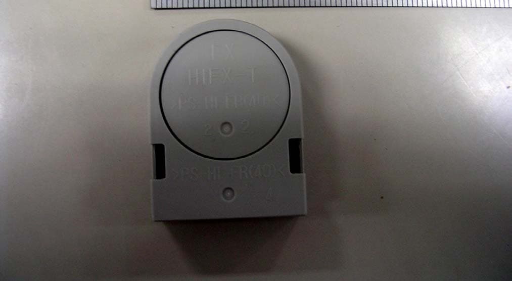
CETECOM ICT Services GmbH Test report no.:2-3126-01-02/03Issue date: 2003-01-20 Page 20 (24) PHOTOGRAPHS OF THE EQUIPMENT HIFX-A Photograph no.:4 CETECOM ICT Services GmbH Test report no.:2-3126-01-02/03Issue date: 2003-01-20 Page 21 (24) PHOTOGRAPHS OF THE EQUIPMENT HIFX-A Photograph no.: 5 CETECOM ICT Services GmbH Test report no.:2-3126-01-02/03Issue date: 2003-01-20 Page 22 (24) PHOTOGRAPHS OF THE EQUIPMENT HIFX-T Photograph no.: 6 CETECOM ICT Services GmbH Test report no.:2-3126-01-02/03Issue date: 2003-01-20 Page 23 (24) PHOTOGRAPHS OF THE EQUIPMENT HIFX-T Photograph no.: 7 CETECOM ICT Services GmbH Test report no.:2-3126-01-02/03Issue date: 2003-01-20 Page 24 (24) PHOTOGRAPHS OF THE EQUIPMENT HIFX-T Photograph no.: 8
Internal Photos
CETECOM ICT Services GmbH Test report no.:2-3126-01-02/03Issue date: 2003-01-20 Page 17 (24) PHOTOGRAPHS OF THE EQUIPMENT HIFX-C Photograph no.: 1 CETECOM ICT Services GmbH Test report no.:2-3126-01-02/03Issue date: 2003-01-20 Page 18 (24) PHOTOGRAPHS OF THE EQUIPMENT HIFX-C Photograph no.:2 CETECOM ICT Services GmbH Test report no.:2-3126-01-02/03Issue date: 2003-01-20 Page 19 (24) PHOTOGRAPHS OF THE EQUIPMENT HIFX-C Photograph no.:3
Test Report
CETECOM ICT Services GmbH Radio Satellite Communication Untertürkheimer Straße 6-10 . D-66117 SaarbrückenTelefon: +49 (0)681 598-9100Telefax: -9075 RSC14issue test report consist of 24 PagesPage 1 (24) Recognized by the Federal Communications Commission FCC–Identification Number: 90462 TCB ID: DE 001 Accredited by the German Accreditation Council DAR–Registration Number TTI–P–G 166/98 Independent ETSI compliance test house ETSI Accredited Bluetooth™ Test Facility (BQTF) Test report no.: 2-3126-01-02/03 FCC Part 15.209 HIFX FCC ID: J2LRFHIFX CETECOM – ICT Services GmbH Untertürkheimerstr. 6-10 66117 Saarbrücken, Germany Telephone: + 49 (0) 681 / 598-0 Fax: + 49 (0) 681 / 9075 BLUETOOTH is a trademark owned by Bluetooth SIG, Inc. and licensed to CETECOM CETECOM ICT Services GmbH Test report no.:2-3126-01-02/03Issue date: 2003-01-20 Page 2 (24) Table of contents 1 General information 1.1 Notes 1.2 Testing laboratory 1.3 Details of applicant 1.4 Application details 1.5 Test item 1.6 Test specifications 2 Technical test 2.1 Summary of test results 2.2 Test report CETECOM ICT Services GmbH Test report no.:2-3126-01-02/03Issue date: 2003-01-20 Page 3 (24) 1 General information 1.1 Notes The test results of this test report relate exclusively to the test item specified in 1.5. The CETECOM ICT Services GmbH does not assume responsibility for any conclusions and generalisations drawn from the test results with regard to other specimens or samples of the type of the equipment represented by the test item. The test report may only be reproduced or published in full. Reproduction or publication of extracts from the report requires the prior written approval of the CETECOM ICT Services GmbH. Test laboratory manager: 2003-01-21RSC - 8411Berg M. DateSectionNameSignature Technical responsibility for area of testing: 2003-01-21RSC - 8412Hausknecht D. DateSectionNameSignature CETECOM ICT Services GmbH Test report no.:2-3126-01-02/03Issue date: 2003-01-20 Page 4 (24) 1.2 Testing laboratory CETECOM ICT Services GmbH Untertürkheimer Straße 6 - 10 66117 Saarbrücken Germany Telephone: + 49 681 598 - 0 Telefax : + 49 681 598 - 9075 E-mail: [email protected] Internet: www.cetecom-ict.de Accredited testing laboratory Accredited by: Regulierungsbehörde für Telekommunikation und Post (RegTP) Listed by: Federal Communications Commission (FCC) AuthorityIdentification/Registration No. RegTPTTI-P-G 166/98-30 FCC90462 1.3Details of applicant Name :FUJI XEROX CO., LTD Street :3-7-1, Funai, Iwatsuki-shi City :Saitama 339-8509 Country :Japan Telephone:+81-48-798-5111 Telex :+81-48-790-1930 E-mail :[email protected] Contact person: Name : Mr. Tsuneo Imada Telephone : +81-48-798-5111 Telex : +81-48-790-1930 E-mail : 1.4Application details Date of receipt of test item : 2003-01-20 Date of test: 2003-01-20 Person(s) who have been : Mr. Masayuki Hirata present during the test: [email protected] CETECOM ICT Services GmbH Test report no.:2-3126-01-02/03Issue date: 2003-01-20 Page 5 (24) 1.5Test item Type of equipment : Paasiv transponder reader for toner cartridges Type designation:HIFX (Part composition: HIFX-C, HIFX-A, HIFX-T) Manufacturer:Same as applicant Street: City: Country: Serial number:- / - Additional information : Frequency:125 kHz Channel spacing:-.- Number of channels :1 Antenna:Integral antenna ERP:59.85 dBμV/m in 3m distance or 19.85 dBμV/m in 300m distance Power supply:3.3V DC ext. Temperature range :0°C - +55°C FCC ID :J2LRFHIFX 1.6Test specifications: FCC Part 15 §15.209 CANADA RSS-210 CETECOM ICT Services GmbH Test report no.:2-3126-01-02/03Issue date: 2003-01-20 Page 6 (24) 2 Technical test 2.1 Summary of test results The radiated measurements are performed in vertical and horizontal plane in the frequency range from 9 kHz to 20 GHz in semi-anechoic chambers. The EUT is positioned on a non- conductive support with a height of 0.80 m above a conductive ground plane that covers the whole chamber. The receiving antennas are conform with specifications ANSI C63.2-1987 clause 15 and ANSI C63.4-1992 clause 4.1.5. These antennas can be moved over the height range between 1.0 m and 4.0 m in order to search for maximum field strength emitted from EUT. The measurement distances between EUT and receiving antennas are indicated in the test set-ups for the various frequency ranges. For each measurement, the EUT is rotated in all three axes until the maximum field strength is received. The wanted and unwanted emissions are received by spectrum analysers where the detector modes and resolution bandwidths over various frequency ranges are set according to requirement ANSI C63-4-1992 clause 4.2. Antennas are conform with ANSI C63.2-1996 item 15. 150 kHz - 30 MHz: Quasi Peak measurement, 9kHz Bandwidth, passive loop antenna . 30 MHz - 200 MHz: Quasi Peak measurement, 120KHz Bandwidth, biconical antenna 200MHz - 1GHz: Quasi Peak measurement, 120KHz Bandwidth, log periodic antenna >1GHz: Average, RBW 1MHz, VBW 10 Hz, wave guide horn All measurement settings are according to FCC 15.35, 15.209. The product fulfils also the requirements for CANADA RSS-210 No deviations from the technical specification(s) were ascertained in the course of the tests performed. FINAL VERDICT : PASS CETECOM ICT Services GmbH Test report no.:2-3126-01-02/03Issue date: 2003-01-20 Page 7 (24) 2.2Test report TEST REPORT Test report no: 2-3126-01-02/03 CETECOM ICT Services GmbH Test report no.:2-3126-01-02/03Issue date: 2003-01-20 Page 8 (24) LIST OF MEASUREMENTS. The list of measured parameters is given below. Clause Page number Transmitter parameters § 15.209Effective radiated RF power9 § 15.209Spurious radiations – Radiated10 Test equipment listing14 Photographs of the equipment16 CETECOM ICT Services GmbH Test report no.:2-3126-01-02/03Issue date: 2003-01-20 Page 9 (24) Equipment under test : HIFX Ambient temperature : 23° °° °C Relative humidity : 33% REFERENCE NUMBER(S) OF TEST EQUIPMENT USED (for reference numbers se…
Text truncated - open the document above for the full version.
Test Report
FUJI XEROX CO., LTD Environmental and Product Safety Department 2274, Hongo Ebina-shi, Kanagawa 243-0494, Japan Name of the standard document; EMC TEST REPORT Form or Standard Number: EPS25-F001 Form revision: k1 Page:1 of 57 Test plan Number: EPS-2002-013 Produced © by FUJI XEROX CO., LTD. EMC Test Report For HIFX EMC Test Site Environment and Product Safety FUJI XEROX CO., LTD. FUJI XEROX CO., LTD Environmental and Product Safety Department 2274, Hongo Ebina-shi, Kanagawa 243-0494, Japan Name of the standard document; EMC TEST REPORT Form or Standard Number: EPS25-F001 Form revision: k1 Page:2 of 57 Test plan Number: EPS-2002-013 Produced © by FUJI XEROX CO., LTD. EMC Test Report Company: Fuji Xerox Co., Ltd. 3-7-1 Funai, Iwatuki-shi, Saitama 335-8509, Japan Trade mark: XEROX Equipment: Passive Transponder Type designation: HIFX(HIFX-C, HIFX-A, HIFX-T) Serial number: #75 Test report number: EPS-RPT2002-025 Test plane number: EPS-2002-024 Standards: EN301 489-1,3 Date of investigation:2003.01.07 Test result: Passed Tested by Takashi Nagakura Tested by Date, Signature ......................................................... Date, Signature Tested by Approved by Masayuki Hirata ......................................................... Date, Signature Date, Signature Remarks 1 This report doesn’t contain a test plan. The test plan of the product is described in “the EMC test plan” independently. As for this result of a test, an examination was done based on this test plan. Remarks 2 EN301489-1,3 isn’t contained in the accreditation range of test site (out of scope). However, the standard that EN301489 quotes it is in the accreditation range. FUJI XEROX CO., LTD Environmental and Product Safety Department 2274, Hongo Ebina-shi, Kanagawa 243-0494, Japan Name of the standard document; EMC TEST REPORT Form or Standard Number: EPS25-F001 Form revision: k1 Page:3 of 57 Test plan Number: EPS-2002-013 Produced © by FUJI XEROX CO., LTD. Summary of the testing results Total Judgment: Passed Table 1 Item Passed Failed Quotation Not applicable Generic Standard EN50 081-1:1992 EN50 081-2:1993 EN50 082-1:1996 EN50 082-2:1995 EN 301 489-1:2002 EN 301 489-3:2002 Product Standard for EMI EN300328: EN300386-1:1994: EN300330-1: EN55 011:1998, Class B (Radiation and Conduction test)) EN55 014: 1998, Class B (Conduction and Clamp test) EN55 022: 1998, Class B (Radiation and Conduction test) EN61 000-3-2: Class D (Harmonics) EN61 000-3-3: (flicker) CISPR Publication 11: 199X CISPR Publication 14: 199X CISPR Publication 22: 199X IEC 61 000-3-2: Class A (Harmonics) IEC 61 000-3-3: (Voltage fluctuation and flicker) FCC Part 15A FCC Part 15B FCC Part15 C FCC Part 68 FUJI XEROX CO., LTD Environmental and Product Safety Department 2274, Hongo Ebina-shi, Kanagawa 243-0494, Japan Name of the standard document; EMC TEST REPORT Form or Standard Number: EPS25-F001 Form revision: k1 Page:4 of 57 Test plan Number: EPS-2002-013 Produced © by FUJI XEROX CO., LTD. Item Passed Failed Quotation Not applicable CNS13438: 1997 AS/NZS 3548: 199X VCCI: 2001 (CISPR Publication 22: 1998) Product Standard for Immunity EN55 014-2:1998 EN55 024:1998 CISPR Publication 14-2:1998 CISPR Publication 24 Item Reference Not applicable Relation Standard IEC/EN 61 000-4-2: 2001 IEC/EN 61 000-4-3: 2001 IEC/EN 61 000-4-4: 2001 IEC/EN 61 000-4-5: 2001 IEC/EN 61 000-4-6: 2001 IEC/EN 61 000-4-8: 2001 IEC/EN 61 000-4-11: 2001 IEC/EN61 000-3-2:2001 : (Harmonics) IEC/EN61 000-3-3:2001 (flicker) EN55 022: 1998, Class B (Radiation and Conduction test) FUJI XEROX CO., LTD Environmental and Product Safety Department 2274, Hongo Ebina-shi, Kanagawa 243-0494, Japan Name of the standard document; EMC TEST REPORT Form or Standard Number: EPS25-F001 Form revision: k1 Page:5 of 57 Test plan Number: EPS-2002-013 Produced © by FUJI XEROX CO., LTD. Content 1. Test site location ..............................................................................................................................................6 1.1 List of test and measurement equipment .....................................................................................................6 2. Equipment under the test ................................................................................................................................7 2.1 Identification of the EUT ...............................................................................................................................7 2.2 Rating of the EUT .........................................................................................................................................8 2.3 Documents reviewed ....................................................................................................................................8 3. Measurement conditions .................................................................................................................................8 3.1 Identification of all Optional Devices / Accessories available for the EUT ...................................................8 3.2 All auxiliary equipment ..................................................................................................................................8 3.3 Description of the EUT..................................................................................................................................9 4.Testing results for Emission (EMI) ............................................................................................................... 11 4.1 General...................................................................................................................................................... 11 4.2 AC Mains ................................................................................................................................................... 11 4.3 Harmonics / Flicker on AC mains ..................................................................................…
Text truncated - open the document above for the full version.
Test Setup Photos
CETECOM ICT Services GmbH Test report no.:2-3126-01-02/03Issue date: 2003-01-20 Page 16 (24) Test site
Contact Information
Applicant
Makoto Fuchigami
Technical Contact
TRP/Cetecom bvbaPhillip Inglis
[email protected]41- 531 3439
14085 Howard Rd · Dayton, Maryland · United States
Non-Technical Contact
TRP/Cetecom bvbaPhillip Inglis
[email protected]410 531 3439
Test Firm
Cetecom ICT Services GmbHRalf Hoehn
Technical Specifications
| # | Rule Parts | Frequency Range | Power Output |
|---|---|---|---|
| 1 | 15C | 0.125 MHz - 0.125 MHz | - |
Other Applications from FUJIFILM Business Innovation Corp.
J2LKDRF
May 29, 2004Limited Modular Transmitter Approval
Equipment Class
DCD - Part 15 Low Power Transmitter Below 1705 kHz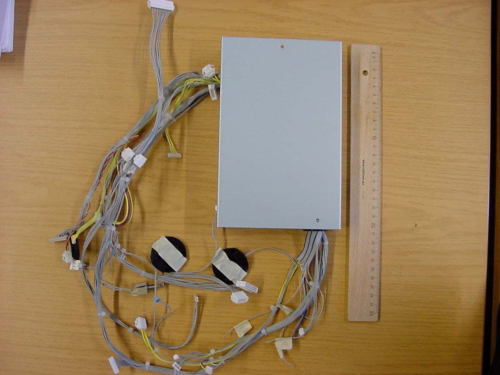
J2LKBRF
Mar 24, 2004Limited Modular Transmitter Approval
Equipment Class
DCD - Part 15 Low Power Transmitter Below 1705 kHz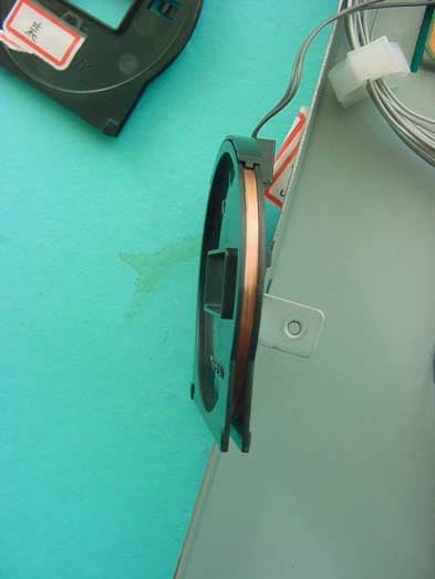
J2LRFGIFX
Oct 30, 2003Limited Modular Transmitter Approval
Equipment Class
DCD - Part 15 Low Power Transmitter Below 1705 kHz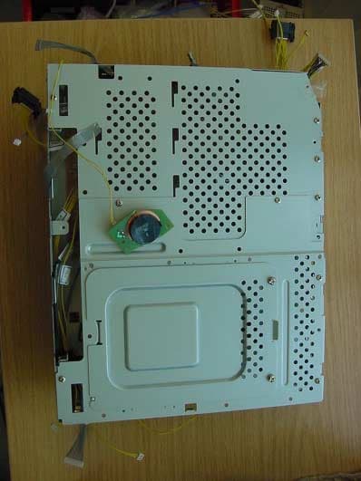
J2LLUFX
Apr 16, 2003Limited Modular Transmitter
Equipment Class
DCD - Part 15 Low Power Transmitter Below 1705 kHz
J2LYIA-7
Oct 14, 2002Printer cartridge toner level reader
Equipment Class
DCD - Part 15 Low Power Transmitter Below 1705 kHz