J2LYIA-7Printer cartridge toner level reader
FUJIFILM Business Innovation Corp.
Click to zoom
Application Details
- Equipment Class
- DCD - Part 15 Low Power Transmitter Below 1705 kHz
- Date of Grant
- Oct 14, 2002
- Application Purpose
- Original Equipment
- Date of Application
- Aug 31, 2002
- Equipment Note
- Printer cartridge toner level reader
- Frequency Range
- 0.12500000 - 0.12500000
- Country
- Japan
Documents & Files
Document Text
Text extracted from the exhibit documents filed with the FCC. Open a document above to read the original.
Users Manual
A3 40ppmLBP(@A4LEF) A3 40ppmLBP(@A4LEF)A3 40ppmLBP(@A4LEF) A3 40ppmLBP(@A4LEF) Operation Manual Operation ManualOperation Manual Operation Manual Ver. 3.0 October. 12, 2000 iiSaja Operation Manual 10/12/00 Chapter0.fm Warning: ï Do not operate the equipment in ways not described in this manual, to prevent the pos- sibility of damage. The manufacturer will not be responsible for any problems or damage that arises from improper use. ï Electrical specifications and safety regulations differ in various countries. You should purchase only a product and consumables designed to be used in your country. Do not take the product or consumables to other countries. ï Contents of this manual are subject to change without prior notice. ï Reproduction of this manual in whole or in part on any kind of media is strictly prohibited. ï Comments about this manual are welcome. If you notice any problems, the manufac- turer would appreciate hearing from you. Saja Operation Manualiii 10/12/00 Chapter0.fm Introduction Thank you for selecting this laser printer. In this manual you will find important information regarding operation and care of your printer. Please read this manual in its entirety and keep it at hand for later reference. Sections marked [!] denote important instructions for assuring safe use of the printer. Pay special attention to these sections and read them fully before operating the printer. This printer is certified as a Class 1 laser product under the U.S. Department of Health and Human Services (DHHS) Radiation Performance Standard according to the Radiation Control for Health and Safety Act of 1968. This means that the printer does not emit haz- ardous laser radiation. Since radiation emitted inside the printer is completely confined within the protective hous- ings and external covers, the laser beam cannot escape from the machine during any phase of user operation. The Center for Devices and Radiological Health (CDRH) of the U.S. Food and Drug Administration implemented regulations for laser products on August 1976. These regula- tions apply to laser products marketed in the United States. The label on the printer indi- cates compliance with the CDRH regulations and must be attached to laser products marketed in the United States. Warning: Use of controls, adjustments or performance of procedures other than those specified in this manual may result in hazardous laser radiation exposure. Radio Interference * Class B Equipment This equipment has been tested and found to comply with the limits for a Class B digital device, pursuant to Part 15 of FCC Rules. These limits are designed to provide reason- able protection against harmful interference in a residential installation. This equipment generates, uses, and can radiate radio frequency energy and, if not installed and used in accordance with the instructions, may cause harmful interference to radio communica- tions. However, there is no guarantee that interference will not occur in a particular instal- lation. If this equipment does cause harmful interference to radio or television reception, which can be determined by turning the equipment off and on, the user is encouraged to try to correct the interference by one or more of the following measures: ï Reorient or relocate the receiving antenna. ï Increase the separation between the equipment and receiver. ï Connect the equipment to an outlet on a circuit different from that to which the receiver is connected. ï Consult with the dealer or an experienced radio/television technician for help. ivSaja Operation Manual 10/12/00 Chapter0.fm What This Manual Contains This manual consists of four chapters and the appendixes section. Chapter 1 Before Installation Describes contents of the package and names of parts, as well as information on how paper travels during the printing process. Chapter 2 Installation Walks you through installing the printer. Be sure to read this chapter before installing the printer. Chapter 3 Daily Operations Explains how to replenish paper, replace the EP cartridge, and perform other tasks neces- sary for day-to-day operations of the printer. Chapter 4 Troubleshooting Covers procedures to isolate and solve problems that may occur during use of the printer. Appendixes The appendixes section contains details on paper, consumables, Optional Paper Cas- settes and Feeder, High Capacity Stacker, Duplex Printing Unit, High Capacity Feeder, and specifications. Saja Operation Manualv 10/12/00 Chapter0.fm Manual Conventions The following conventions are used in this manual. Important: Provides information required to successfully complete an operation or pro- cedure. Be sure to read this before performing the relevant operation. Note:Provides useful additional information. Reference: Provides further information for reference. Throughout the manual, the personal computer or workstation to which the printer is to be connected is called the ìhost computerî. viSaja Operation Manual 10/12/00 Chapter0.fm Features This printer offers the following outstanding features. High-quality printing The laser printer engine assures razor-sharp output of graphics and text, even at very small point sizes, at resolution up to 1200 dpi x 1200 dpi (Option). Ergonomic operation The easy-to-read display clearly shows the operation status of the printer. Ergonomically shaped front-panel buttons are used to control all functions. User-friendly EP cartridge The integrated EP cartridge contains both the toner and the photosensitive drum in a sin- gle housing, which makes it easy to replace the cartridge. Flexible paper handling The front-side paper tray can be set for a wide variety of paper sizes, both standard and non-standard max. 305 x 508 mm, including extended A3 for camera-ready copy. It can also accommodate envelopes and labels. The paper cassette is a universal type which can hold up to 500 sheets and can be set to any size from A3 to A5. A dedicated cassette that can hold 500 sheets of extende…
Text truncated - open the document above for the full version.
Users Manual
4-12Saja Operation Manual 10/12/00 Troubleshooting Chapter4.fm When E1 or E2 is shown When the status code E1 or E2 is shown, paper is jammed between the paper feed section (front paper tray or the cassette) and the EP cartridge. Clear the paper jam as follows. 1. Open the top cover all the way to the back until it stops. If the front paper tray is closed, open it. Warning: Make sure the top cover is opened all the way to the back until it stops. (Also, when closing, slowly close the top cover.) Important:If printouts still remain in the paper output tray, remove them before opening the top cover; otherwise paper jam may result. Do not touch any parts inside the printer. 2. If paper was fed from the front paper tray, remove all paper from the tray. Saja Operation Manual4-13 10/12/00 Chapter4.fmTroubleshooting 3. Check the far end of the front paper tray (near the paper inlet slot), and remove any jammed paper. 4. If paper was fed from the cassette, pull the cassette out of the printer. If the optional paper feeder is installed, remove all paper cassettes from the paper feeder as well. 4-14Saja Operation Manual 10/12/00 Troubleshooting Chapter4.fm 5. If there is wrinkled paper in the cassette, remove it. 6. Check the far end of the cassette feeder, and remove any jammed paper. Caution: Be careful not to damage any components inside the printer. If the optional paper feeder is installed, check the far end of the cas- sette feeder. Then open the rear cover of the feeder and remove any jammed paper. Saja Operation Manual4-15 10/12/00 Chapter4.fmTroubleshooting If the jammed paper could be removed by these steps, proceed to step 13 to complete the procedure. If there is still jammed paper in the printer or if the error message does not disappear even after the top cover is closed, proceed to the next step. 4-16Saja Operation Manual 10/12/00 Troubleshooting Chapter4.fm 7. Hold both sides of the tray and tilt it slightly. Then, gently lift the tray up and then pull it towards you. 8. Hold the EP cartridge as shown in the illustration and pull it out slowly. Note:To prevent stains, place the cartridge on a surface cov- ered with some old newspaper. 9. Check the area where the EP cartridge was located, and remove any jammed paper. Note:If you cannot see any paper, check the far end of the front paper tray. Saja Operation Manual4-17 10/12/00 Chapter4.fmTroubleshooting 10. Return the paper tray to its normal position. Hold both sides of the paper tray and push it into the printer until it stops. Lift it up gently, and then further push it to return it to its original position. 11. Hold the EP cartridge as shown. Then, ➀ insert the projecting parts on the cartridge into the guide channels of the printer, and ➁ lower the cartridge into the printer. Important:Do not touch any parts inside the printer. 12. Push the EP cartridge all the way in. Important:Make sure the cartridge is seated properly. 4-18Saja Operation Manual 10/12/00 Troubleshooting Chapter4.fm 13. Reinsert the cassette in the printer. Push the cassette fully in until it locks. If the optional paper feeder is installed, replace the paper cassette removed earlier. 14. Close the top cover. Press the center part of the top cover until it locks securely. Important:Make sure the top cover is properly locked. Otherwise print quality problems may occur. If the top cover cannot be closed, remove the EP car- tridge completely and reinsert it all the way into the printer. Then try to close the top cover again. Saja Operation Manual4-19 10/12/00 Chapter4.fmTroubleshooting 15. Check the display and make sure the printer is ready for printing. Important:Also if the paper jam was located only in the front paper tray or the cassette, the error message does not disap- pear unless the top cover is opened and closed again. The next sheet that emerges from the printer after a paper jam may be stained, but staining should disappear after a few sheets. When E3 or E4 is shown When the status code E3 is shown, paper is jammed between the EP car- tridge and the paper exit slot. When the status code E4 is shown, paper is jammed in the vicinity of the paper exit slot. Clear the paper jam as follows. 1. Open the top cover all the way to the back until it stops. If the front paper tray is closed, open it. Warning: Make sure the top cover is opened all the way to the back until it stops. (Also, when closing, slowly close the top cover.) Important:If printouts still remain in the paper output tray, remove them before opening the top cover; otherwise paper jam may result. Do not touch any parts inside the printer. PRINT RDY 4-20Saja Operation Manual 10/12/00 Troubleshooting Chapter4.fm 2. If paper was fed from the front paper tray, remove all paper from the tray. 3. Check the far end of the front paper tray (near the paper inlet slot), and remove any jammed paper. 4. If paper was fed from the cassette, pull the cassette out of the printer. Saja Operation Manual4-21 10/12/00 Chapter4.fmTroubleshooting If the optional paper feeder is installed, remove all paper cassettes from the paper feeder as well. 5. If there is wrinkled paper in the cassette, remove it. 6. Check the far end of the cassette feeder, and remove any jammed paper. Caution: Be careful not to damage any components inside the printer. 4-22Saja Operation Manual 10/12/00 Troubleshooting Chapter4.fm If the optional paper feeder is installed, check the far end of the cas- sette feeder. The open the rear cover of the feeder and remove any jammed paper. Saja Operation Manual4-23 10/12/00 Chapter4.fmTroubleshooting 7. Pull on the recessed area to open the top rear cover, as shown. 8. Open the lever on the left side of the fuser and remove any jammed paper. Caution: Before touching the fuser to remove any jammed paper, be sure to turn off the power and wait for 40 minutes to allow the printer to cool down. 4-24Saja Operation Manual 10/12/00 Troubleshooting Chapter4.fm 9. Re-insert the fuser and close the rear cover…
Text truncated - open the document above for the full version.
Cover Letter(s)
TRP Inc 14085 Howard Rd Dayton, MD 21036 September 1, 2002 Federal Communications Commission 7435 Oakland Mills Road Columbia, MD 21043 Gentlemen: On behalf of Fuji Xerox Corporation Limited, 7-1 Funai 3-Chome, Iwatsuki-shi, Saitama-ken, Japan 339 please find the attached Equipment Authorization application for a Low Power Communications Device operating on a frequency of 125 kHz. The low power transmitter is installed within the printer as part of the assembly and is used to provide readout of the level of toner remaining in the printer toner cartridge. The printer is a peripheral to a personal computer and has been verified as compliant with the digital device requirements. Sincerely, Phillip Inglis TRP/Cetecom bvba Consultant
Cover Letter(s)
CONFIDENTIALITY REQUEST September 1, 2002 Federal Communications Commission Authorization and Evaluation Division 7435 Oakland Mills Road Columbia, MD 21046 Re: Fuji Xerox Corporation Limited, 7-1 Funai 3-Chome, Iwatsuki-shi, Saitama-ken, Japan 339 , FCC ID:J2LYIA-7 Gentlemen: Fuji Xerox Corporation Limited, 7-1 Funai 3-Chome, Iwatsuki-shi, Saitama-ken, Japan 339 herein submits an application for Equipment Authorization to be followed by submission of the necessary fees for certification of a base station transmitter under FCC Rules Part 15 as required by the FCC Rules. Fuji Xerox Corporation Limited, 7-1 Funai 3-Chome, Iwatsuki-shi, Saitama-ken, Japan 339 requests, pursuant to 47CFR 0.459, post grant confidentiality for portions of the material contained in this application such that the identified material will be withheld from public inspection following the grant of this authorization. This material, as indicated by request for confidentiality of the items during the electronic submission process and further identified below, includes: 1. Circuit diagrams submitted as Equipment Authorization electronic filing attachment: "Schematics". 2. Block diagram submitted as Equipment Authorization electronic filing attachment: "Block Diagram". 3. Technical description submitted as Equipment Authorization electronic filing attachment: "Technical Description". Specifically, these exhibits contain information relating to circuit function and complexity that could be of benefit to competitors. The material contains trade secrets and confidential information that EADS-Defense & Security Networks does not customarily release to the public and which is otherwise not generally available to the public. Please contact the undersigned by telephone at 410-531-3439, by fax at 410-531-0807, by email at [email protected], or by correspondence at the address below if there are any further questions or additional information needed concerning this filing. Regards, (signed) Phillip Inglis, TRP/Cetecom b.v.b.a. 14085 Howard Rd. Dayton, MD. 21036
External Photos
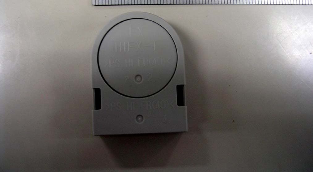
CETECOM ICT Services GmbH Test report no.:2-2984-01-02/02Issue date: 2002-08-22 Page 22 (34) PHOTOGRAPHS OF THE EQUIPMENT YIA-7 Photograph no.: 1 CETECOM ICT Services GmbH Test report no.:2-2984-01-02/02Issue date: 2002-08-22 Page 23 (34) PHOTOGRAPHS OF THE EQUIPMENT YIA-7 Photograph no.:2
ID Label/Location Info
FCC ID label: The following label will be placed on the bottom of the printer: FCCID:J2LYIA-7 This device complies with Part 15 of the FCC Rules. Operation is subject to the following two conditions: (1) this device may not cause harmful interference, and (2) this device must accept any interference received, including interference that may cause undesired operation. .
ID Label/Location Info
FCC ID label location: The following label will be placed on the bottom of the printer: FCCID:J2LYIA-7 This device complies with Part 15 of the FCC Rules. Operation is subject to the following two conditions: (1) this device may not cause harmful interference, and (2) this device must accept any interference received, including interference that may cause undesired operation.
Internal Photos
CETECOM ICT Services GmbH Test report no.:2-2984-01-02/02Issue date: 2002-08-22 Page 24 (34) PHOTOGRAPHS OF THE EQUIPMENT YIA-7 Photograph no.:3 CETECOM ICT Services GmbH Test report no.:2-2984-01-02/02Issue date: 2002-08-22 Page 25 (34) PHOTOGRAPHS OF THE EQUIPMENT YIA-7 Photograph no.:4 CETECOM ICT Services GmbH Test report no.:2-2984-01-02/02Issue date: 2002-08-22 Page 26 (34) PHOTOGRAPHS OF THE EQUIPMENT YIA-7 Photograph no.: 5 CETECOM ICT Services GmbH Test report no.:2-2984-01-02/02Issue date: 2002-08-22 Page 27 (34) PHOTOGRAPHS OF THE EQUIPMENT YIA-7 Photograph no.: 6 CETECOM ICT Services GmbH Test report no.:2-2984-01-02/02Issue date: 2002-08-22 Page 28 (34) PHOTOGRAPHS OF THE EQUIPMENT YIA-7 Photograph no.: 7 CETECOM ICT Services GmbH Test report no.:2-2984-01-02/02Issue date: 2002-08-22 Page 29 (34) PHOTOGRAPHS OF THE EQUIPMENT YIA-7 Photograph no.: 8 CETECOM ICT Services GmbH Test report no.:2-2984-01-02/02Issue date: 2002-08-22 Page 30 (34) PHOTOGRAPHS OF THE EQUIPMENT YIA-7 Photograph no.: 9 CETECOM ICT Services GmbH Test report no.:2-2984-01-02/02Issue date: 2002-08-22 Page 31 (34) PHOTOGRAPHS OF THE EQUIPMENT YIA-7 Photograph no.: 10 CETECOM ICT Services GmbH Test report no.:2-2984-01-02/02Issue date: 2002-08-22 Page 32 (34) PHOTOGRAPHS OF THE EQUIPMENT YIA-7 Photograph no.: 11 CETECOM ICT Services GmbH Test report no.:2-2984-01-02/02Issue date: 2002-08-22 Page 33 (34) PHOTOGRAPHS OF THE EQUIPMENT YIA-7 Photograph no.: 12 CETECOM ICT Services GmbH Test report no.:2-2984-01-02/02Issue date: 2002-08-22 Page 34 (34) PHOTOGRAPHS OF THE EQUIPMENT YIA-7 Photograph no.: 13
RF Exposure Info
This device is exempt from routine filing of RF exposure information.
Test Report
CETECOM ICT Services GmbH Radio Satellite Communication Untertürkheimer Straße 6-10 . D-66117 SaarbrückenTelefon: +49 (0)681 598-9100Telefax: -9075 RSC14issue test report consist of 34 PagesPage 1 (34) TTI-P-G166/98-30 Accredited Bluetooth™ Test Facility (BQTF) Test report no.: 2-2984-01-02/02 FCC Part 15.209 YIA-7 FCC ID: J2LYIA-7 CETECOM – ICT Services GmbH Untertürkheimerstr. 6-10 66117 Saarbrücken, Germany Telephone: + 49 (0) 681 / 598-0 Fax: + 49 (0) 681 / 9075 BLUETOOTH is a trademark owned by Bluetooth SIG, Inc. and licensed to CETECOM CETECOM ICT Services GmbH Test report no.:2-2984-01-02/02Issue date: 2002-08-22 Page 2 (34) Table of contents 1 General information 1.1 Notes 1.2 Testing laboratory 1.3 Details of applicant 1.4 Application details 1.5 Test item 1.6 Test standards 2 Technical test 2.1 Summary of test results 2.2 Test report 1 General information 1.1 Notes The test results of this test report relate exclusively to the test item specified in 1.5. The CETECOM ICT Services GmbH does not assume responsibility for any conclusions and generalisations drawn from the test results with regard to other specimens or samples of the type of the equipment represented by the test item. The test report may only be reproduced or published in full. Reproduction or publication of extracts from the report requires the prior written approval of the CETECOM ICT Services GmbH. 1.2Testing laboratory CETECOM ICT Services GmbH Untertürkheimer Straße 6 - 10 66117 Saarbrücken Germany Telephone: + 49 681 598 - 0 Telefax : + 49 681 598 - 9075 E-mail: [email protected] Internet: www.cetecom-ict.de Accredited testing laboratory DAR-registration number : TTI-P-G-166/98-30 Accredited Bluetooth™ Test Facility (BQTF) BLUETOOTH is a trademark owned by Bluetooth SIG, Inc. and licensed to CETECOM CETECOM ICT Services GmbH Test report no.:2-2984-01-02/02Issue date: 2002-08-22 Page 3 (34) 1.3Details of applicant Name : FUJI XEROX CO., LTD Street : 2274, Hongo, Ebina-shi City : Kanagawa 243-0494 Country : Japan Telephone : +81-46-238-3111 Telefax : +81-46-238-5796 Contact : Mr. Tsuneo Obara Telephone: +81-46-238-3111 1.4Application details Date of receipt of application : 2002-08-02 Date of receipt of test item : 2002-08-19 Date of test : 2002-08-20/22 1.5Test item Type of equipment : Toner cartridge identification Type designation: YIA-7 Manufacturer:applicant Street: City: Country: Serial number:See photo FCC ID:J2LYIA-7 Additional information : Frequency: 124,9842 kHz Type of modulation: 2K00F1D Number of channels :1 Antenna:Loop antenna Power supply:115V AC Type of equipment:Passiv Transponder Reader built in an Printer Temperature range : ±0°C - +55°C Output power:10dBμV/m in 300m / 3.1623 in 300m or 30 nW ERP 1.6Test standards FCC Part 15.209 CETECOM ICT Services GmbH Test report no.:2-2984-01-02/02Issue date: 2002-08-22 Page 4 (34) 2 Technical test 2.1 Summary of test results The radiated measurements were performed vertical and horizontal over the whole frequency range. We start at 1 m high with vertical receiving antenna and rotate the dish continuously. During rotation we use the antenna lift system to vary the high from 1 to 4 m. So we find maximum radiation output. At this points we do manual re-measurements. After this we do the same measurements in horizontal position of the receiving antenna. This (horizontal and vertical) is made for all the three planes of the test sample. We use the maximum received results. The detector function and selection of bandwidth are according ANSI C63.2-1996 item 8.2.1 and ANSI C63.4-1992 Item 4.2. Antennas are conform with ANSI C63.2-1996 item 15. 9 kHz - 30 MHz: Quasi Peak measurement, 9kHz Bandwidth, passive loop antenna. 30 MHz - 200 MHz: Quasi Peak measurement, 120KHz Bandwidth, biconical antenna 200MHz - 1GHz: Quasi Peak measurement, 120KHz Bandwidth, log periodic antenna 1GHz: Average, RBW 1MHz, VBW 10 MHz, waveguide horn No deviations from the technical specification(s) were ascertained in the course of the tests performed. Final verdict : PASS Technical responsibility for area of testing : 2002-08-22RSC 8414 Ames H. DateSectionNameSignature 2002-08-22RSC 8411 Berg M. DateSectionNameSignature CETECOM ICT Services GmbH Test report no.:2-2984-01-02/02Issue date: 2002-08-22 Page 5 (34) 2.2Test report TEST REPORT Test report no: 2-2984-01-02/02 CETECOM ICT Services GmbH Test report no.:2-2984-01-02/02Issue date: 2002-08-22 Page 6 (34) LIST OF MEASUREMENTS. The list of measured parameters is given below. Clause Page number Transmitter parameters § 15.209Effective radiated RF power7 § 15.209Spurious radiations – Radiated30 § 15.207 Conducted emissions 50 Test equipment listing35 Photographs of the equipment37 CETECOM ICT Services GmbH Test report no.:2-2984-01-02/02Issue date: 2002-08-22 Page 7 (34) Equipment under test : YIA-7 Ambient temperature : 26° °° °C Relative humidity : 47% REFERENCE NUMBER(S) OF TEST EQUIPMENT USED (for reference numbers see test equipment listing) 17 - 24 MAXIMUM PEAK OUTPUT POWER (RADIATED) TEST CONDITIONSMAXIMUM PEAK OUTPUT POWER (μV/m) Frequency (MHz)124,9842 kHz T nom ( 26 )° °° °C V nom ( 115 )V3.1623μV/m (10 dBμV/m) Maximum deviation from output power under extreme test conditions (dBc) not applicable Measurement uncertainty±3dB RBW/VBW : 0,2kHz Limit for 124,9842 kHz is 19.20 μV/m in 300m measurement distance Limits SUBCLAUSE § 15.209 Frequency (MHz)Field strength (μV/m)Measurement distance (m) 0.009 – 0.4902400/F(kHz)300 0.490 – 1.70524000/F(kHz)30 1.705 – 30.03030 30 - 881003 88 - 2161503 216 - 9602003 above 9605003 CETECOM ICT Services GmbH Test report no.:2-2984-01-02/02Issue date: 2002-08-22 Page 8 (34) Equipment under test : YIA-7 Ambient temperature : 26° °° °C Relative humidity : 47% REFERENCE NUMBER(S) OF TEST EQUIPMENT USED (for reference numbers see test equipment listing) 17 - 24 SPURIOUS RADIATION § 15.209 Radiated RF Power on Data File : /22984_05.DOC 20 Aug 1902 15:28:30 ----------------------------------------…
Text truncated - open the document above for the full version.
Test Setup Photos
CETECOM ICT Services GmbH Test report no.:2-2984-01-02/02Issue date: 2002-08-22 Page 19 (34) 68 Photographs of the equipment Test site CETECOM ICT Services GmbH Test report no.:2-2984-01-02/02Issue date: 2002-08-22 Page 20 (34) Photographs of the equipment Test site
Contact Information
Applicant
Makoto Fuchigami
Technical Contact
TRP/Cetecom bvbaPhillip Inglis
[email protected]410 531 3439
14085 Howard Rd · Dayton, Maryland · United States
Non-Technical Contact
TRP/Cetecom bvbaPhillip Inglis
[email protected]410 531 3439
Test Firm
Cetecom ICT Services GmbHRalf Hoehn
Technical Specifications
| # | Rule Parts | Frequency Range | Power Output |
|---|---|---|---|
| 1 | 15C | 0.125 MHz - 0.125 MHz | - |
Other Applications from FUJIFILM Business Innovation Corp.
J2LKDRF
May 29, 2004Limited Modular Transmitter Approval
Equipment Class
DCD - Part 15 Low Power Transmitter Below 1705 kHz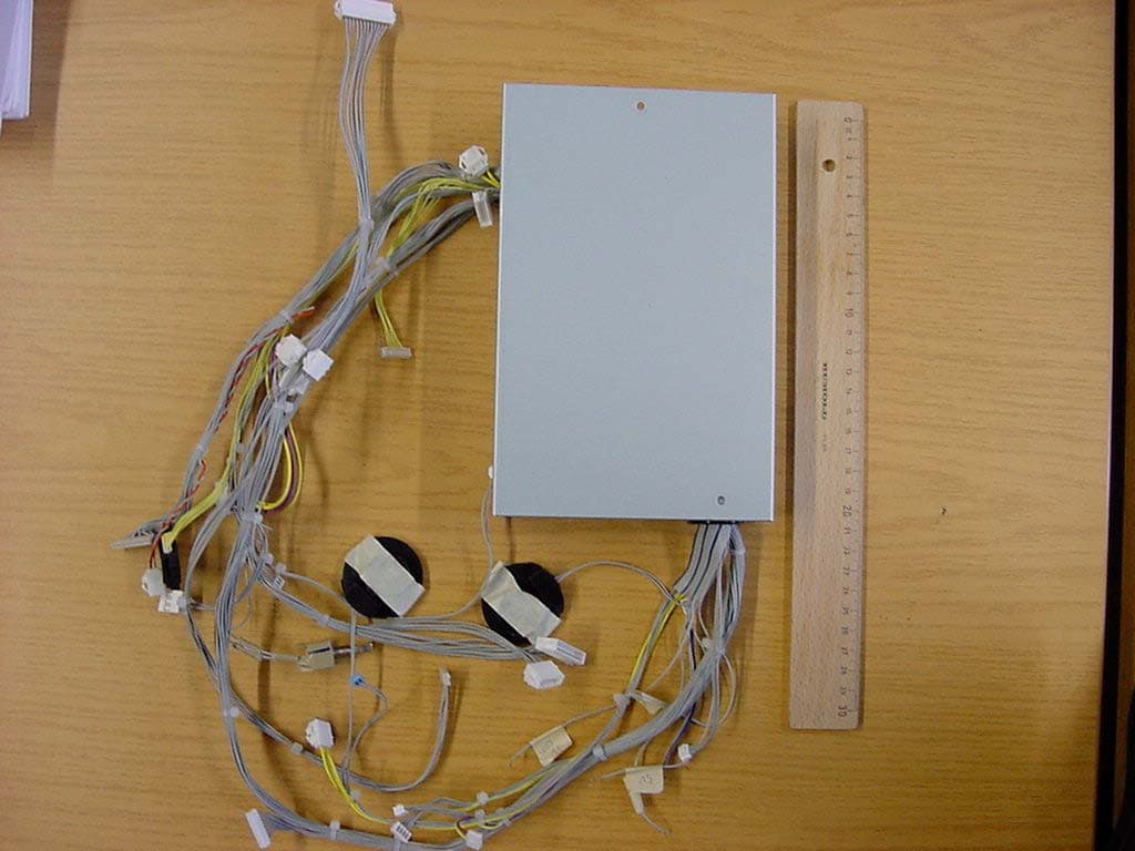
J2LKBRF
Mar 24, 2004Limited Modular Transmitter Approval
Equipment Class
DCD - Part 15 Low Power Transmitter Below 1705 kHz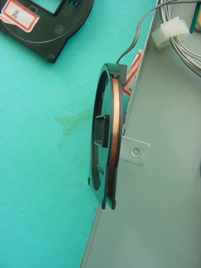
J2LRFGIFX
Oct 30, 2003Limited Modular Transmitter Approval
Equipment Class
DCD - Part 15 Low Power Transmitter Below 1705 kHz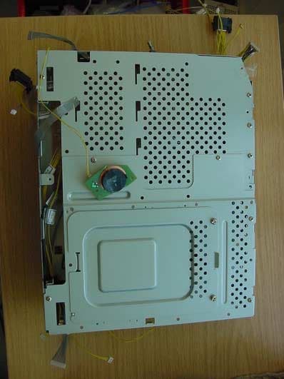
J2LLUFX
Apr 16, 2003Limited Modular Transmitter
Equipment Class
DCD - Part 15 Low Power Transmitter Below 1705 kHz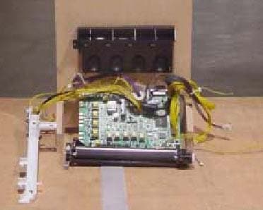
J2LRFHIFX
Apr 15, 2003Limited Modular Transmitter
Equipment Class
DCD - Part 15 Low Power Transmitter Below 1705 kHz