JF6-8000-2UDigital Transmission System Transmitter
Alcatel USA Marketing, Inc.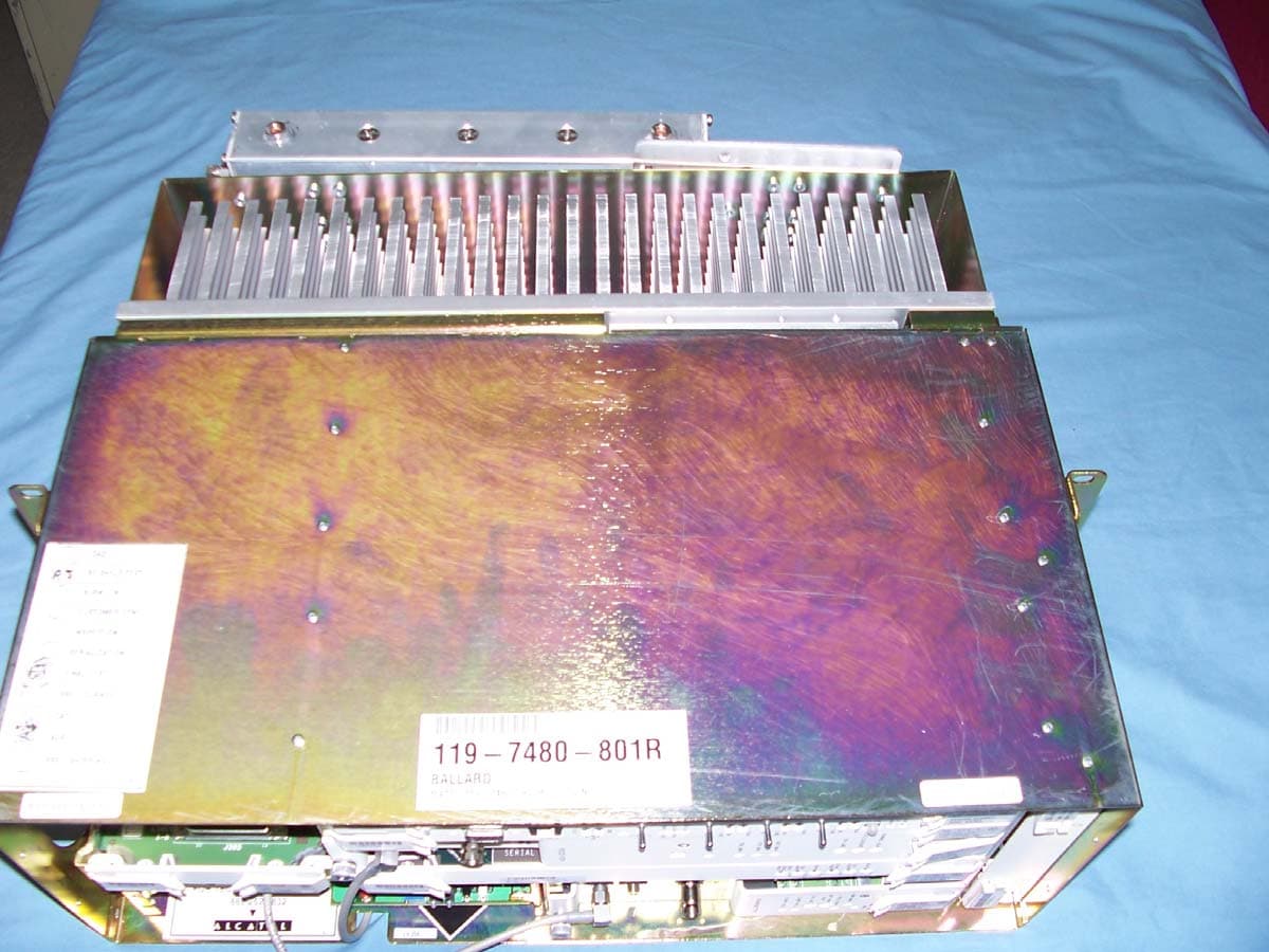
Click to zoom
Application Details
- Equipment Class
- DTS - Digital Transmission System
- Date of Grant
- Oct 24, 2006
- Application Purpose
- Original Equipment
- Date of Application
- Sep 04, 2006
- Equipment Note
- Digital Transmission System Transmitter
- Frequency Range
- 2402.50000000 - 2480.37500000
- Company
- Alcatel USA Marketing, Inc.
- Country
- United States
Documents & Files
Document Text
Text extracted from the exhibit documents filed with the FCC. Open a document above to read the original.
Users Manual
2-5 Issue 1 3EM20188AAAA June 2006 Applications Section 2 APPLICATIONS 2.1 INTRODUCTION The MDR-8000 family of microwave radios is specifically designed to satisfy the evolving needs of public, private, government, and international networks. Each DS1/E1 radio offers the flexibility of 2, 4, 8, 12, 16 DS1s or E1s to meet the need for low capacity domestic or inter- national systems. Each DS3 radio offers up to three DS3s with equal number of wayside DS1s to meet domestic high capacity system requirements. Each OC3/STM-1 radio offers one or three STS1s with equal number of wayside DS1s or E1s to meet domestic or international Synchronous Optical Network (SONET) system requirements. The MDR-8000E Ethernet radio provides transport for IP/packet data in licensed and unlicensed frequency bands. The radio supports 10baseT, 100baseT, and 1000baseT interface rates with auto-negotiation and can be configured to transport low and high capacity data at RF frequencies in the 2, 4, 5, 6, 7/ 8, and 10/11 GHz bands. The number of channels transmitted and the RF channel bandwidth depend on the capacity keys installed in the transmitter and receiver modules. The modulation formats are 32 or 128 TCM (DS1/E1), 64 QAM (DS3), and 128 TCM (OC3/STM-1). Growth in DS1/E1 system capacity can be performed in service and requires only exchanging capacity keys. Growth from DS1/ E1 to DS3 system capacity is an out-of-service procedure and requires exchanging modules and capacity keys. Changing to OC3/STM-1 system capacity is performed out-of-service and requires exchanging modules, and capacity keys. All radios are available in 1:0 non-standby (NS) and 1:1 hot-standby (HS) and frequency diver- sity (FD). The HS version allows for troubleshooting and module replacement, on an in-service basis. Space diversity can be added to any of the three basic configurations. In addition to the three basic configurations, the OC3/STM-1 radio is available with a 0:2 dual channel (no pro- tection) equipment configuration and the protected OC3/STM-1 radio is also available in a 2 X 4-fiber or 4-fiber cable configuration. 2.2 TYPICAL USERS Because of unique flexibility in both frequency and capacity, the MDR-8000/i/s can be used for a variety of voice, data, and video applications, for many types of users, some of which are listed as follows: • Personal Communication Systems (PCS) • Cellular Operators • Common Carriers • Alternate Access and Competitive Access Providers (CAP) • Private Networks • Educational Institutions • State, Local, and Federal Government Systems • International Users. 2.3 UNLICENSED RADIO The MDR-8X05U/8X02U (unlicensed) radio provides fast deployment of service with microwave radio No license and small antennas (no FCC requirements) allow immediate turnup. After the license is received, the unlicensed radio can be easily converted to the lower 6 GHz licensed band. 2-6 Issue 1 Applications Section June 2006 3EM20188AAAA Refer to drawing 3DH031770001BJZZA in Volume 2 for configurations and equipping options. The MDR-8X05U radio operates in the 5725-5850 and 2400-2483.5 Information, Scientific, and Medical (ISM) band in accordance with FCC Part 15.247 of the FCC rules. Any changes or modifications not expressly approved by the manufacturer could void the user’s authority to operate the equipment. This unlicensed radio, although operating in the same band as a spread spectrum radio, operates using narrower bandwidths than spread spectrum. Advantages, disadvantages, and antenna recommendations for the unlicensed radio follow: 2.3.1 Advantages • Fast installation and turnup • 2, 4, 8, 16 DS1, DS3, and OC3/STM-1 capacities • Field convertible to lower 6 GHz licensed band • Field expandable to higher capacities. • Common network management with licensed radios. • Common spares and training with licensed radios 2.3.2 Disadvantages • No interference protection • Operating restrictions • 5.725 to 5.850 GHz band/2.4 to 2.4835 GHz • Performance could deteriorate due to interference as the frequency band becomes congested. 2.3.3 Antenna Recommendations • Frequency – 5.8 GHz/2.4 GHz • Size and Type – 2, 4, 6, 8, or 10 foot parabolic; 1 or 2 foot flat panel. • Gain and Beamwidth (3 dB) 5.8 GHz 2.4 GHz 2 ft parabolic – 29 dB/6 û 2 ft parabolic – 20 dB/13.8 û 4 ft parabolic – 35 dB/3 û 4 ft parabolic – 27 dB/6.9 û 6 ft parabolic – 38 dB/2 û 6 ft parabolic – 30.5 dB/4.6 û 8 ft parabolic – 41 dB/1.5 û 8 ft parabolic – 33.3 dB/3.5 û 10 ft parabolic – 42.5 dB/1.2 û 10 ft parabolic – 35.2 dB/2.8 û Note When using a 1 ft flat panel antenna with a 1 watt (+30 dBm) output power, the antenna must be located in an area that does not allow the general pop- ulation access to within 5 feet of the antenna. 5.8 GHz 2.4 GHz 1 ft flat panel – 23 dB/9 û 1 ft flat panel – 18 dB/30 û 2 ft flat panel – 28 dB/3.5 û
Users Manual
MDR-8000/i/s/u Alcatel Part Number 3EM15726AA 3400 West Plano Parkway Plano, Texas 75075-5813 U.S.A. Part 1 of 2 Issue 2, June, 2004 Microwave Digital Radios Users Manual Table of Contents TOC-i Page Section 1General 1.1 INTRODUCTION ............................................................................................. 1-1 1.2 CONTENT ....................................................................................................... 1-1 Section 2Operation 2.1 GENERAL ........................................................................................................ 2-1 2.2 TURN-ON ........................................................................................................ 2-1 2.3 USER SYSTEM INTERFACE (USI) PROVISIONING FUNCTION/OPERATION ...... 2-2 2.4 OPERATING PROCEDURES .............................................................................. 2-2 2.4.1 Radio Receiver Manual Switching ..................................................................... 2-2 2.4.2 Radio Transmitter Manual Switching ................................................................. 2-5 2.4.3 Radio I/O Interface Manual Switching .............................................................. 2-5 2.4.4 MCS-11 Operation .......................................................................................... 2-7 2.4.5 Lamp Tests ....................................................................................................... 2-8 2.4.6 Alarm Checks .................................................................................................. 2-8 2.4.7 Orderwire Operation ....................................................................................... 2-8 2.4.8 Initiating Outgoing Orderwire Calls .................................................................. 2-8 2.4.9 Answering Incoming Orderwire Calls ................................................................ 2-8 2.5 TURN-OFF PROCEDURE ................................................................................... 2-9 2.6 EMERGENCY OPERATION .............................................................................. 2-9 2.7 MODEM OPERATION ...................................................................................... 2-9 2.8 CONTROLS, INDICATORS, TEST POINTS, AND CONNECTORS ....................... 2-9 Section 3Interconnect 3.1 SECTION INTRODUCTION .............................................................................. 3-1 3.2 INSTALL POWER CABLE ASSEMBLIES ............................................................... 3-1 Page TOC-ii 3.3 PDU STRAPPING AND CONNECTIONS ........................................................... 3-3 3.4 SHELF/RACK ALARM CONNECTION .............................................................. 3-5 3.5 DS1 CONNECTIONS (J303 IN AND J304 OUT) .............................................. 3-8 3.6 DS1 REPEATER (J314 ON ONE SHELF TO J314 ON SECOND SHELF) ............ 3-10 3.7 DS3 LBO STRAPPING AND CONNECTIONS ................................................. 3-11 3.8 DS3 LBO DS3 BNC CONNECTIONS (J21 THROUGH J26 ) ............................. 3-12 3.9 DS3 LBO WAYSIDE DS1 CONNECTIONS (J201 IN AND J202 OUT ) ............. 3-13 3.9.1 Wayside DS1 Terminal .................................................................................. 3-14 3.9.2 Wayside DS1 Repeater .................................................................................. 3-15 3.10 DS3 REPEATER (J401 ON ONE SHELF TO J401 ON SECOND SHELF) ............ 3-15 3.11 FIBER OPTIC CABLE CONNECTIONS ............................................................. 3-16 3.11.1 2 or 4 Fiber Management Panel ..................................................................... 3-17 3.11.2 2x4 Fiber Switched Management Panel .......................................................... 3-17 3.12 OC3 AUX INTERFACE BOARD WAYSIDE DS1 CONNECTIONS (J201 IN AND J202 OUT) .............................................................................. 3-20 3.12.1 Wayside DS1 Terminal .................................................................................. 3-20 3.12.2 Wayside DS1 Repeater .................................................................................. 3-20 3.13 OC3 REPEATER (J203 ON ONE SHELF TO J203 ON SECOND SHELF) ........... 3-21 3.14 USI/CONTROLLER CABLE CONNECTION TO LAPTOP (J301) ......................... 3-22 3.15 SERVICE CHANNEL ....................................................................................... 3-22 3.15.1 Handset Jack ................................................................................................. 3-23 3.15.2 Service Channels Provisioning Options ............................................................ 3-24 3.15.3 Audio 1, Audio 2 (J316, J317) ....................................................................... 3-24 3.15.4 RS-232-1, RS-232-2 (J312, J313) .................................................................... 3-27 3.15.5 MCS-11 Connections ..................................................................................... 3-28 3.15.6 ELMC (J315, J318) ........................................................................................ 3-37 3.16 FOREIGN ALARM INTERFACE (J305) ............................................................. 3-41 3.17 ALARM, STATUS, CONTROLS INTERCONNECT ............................................. 3-44 3.17.1 Controller Bus ................................................................................................ 3-46 3.17.2 Control Inputs ................................................................................................ 3-46 3.17.3 Station Alarm Inputs/TBOS Interface ............................................................... 3-46 Page TOC-iii 3.17.4 Station Alarm Wiring ..................................................................................... 3-47 3.17.5 Relay Alarm/Status Outputs .............................................................…
Text truncated - open the document above for the full version.
Users Manual
MDR-8000/i/s/u Alcatel Part Number 3EM15726AA 3400 West Plano Parkway Plano, Texas 75075-5813 U.S.A. Part 2 of 2 Issue 2, June, 2004 Microwave Digital Radios Users Manual 4-1 4 INITIAL TURNUP 4.1 SECTION INTRODUCTION This section describes the procedures required to turn up the MDR-8000 Microwave Digital Radios after installation. This provisioning part of the section describes provisioning options available with the MDR-8000 software application. Provisioning allows for the definition, editing, and storing of specific functions. The MDR-8000 provides the ability to provision equipment and facili- ties through a series of Windows™-based screens and messages. The Provisioning menu lists equipment and functions which may be provisioned. You should use only those provi- sioning screens that are applicable to your radio. Refer to the Users Guide section and applicable DS1/E1, DS3, or OC3 Initial Turnup section on the attached CD for more infor- mation. 4.2 RECOMMENDED SEQUENCE Perform the following initial turnup procedures in sequence: 1 Install software on PC. Software installed at the factory before delivery should not be overwrit- ten by downloading to the radio controller at initial turnup. Refer to Maintenance section on the attached CD for procedure to upgrade exist- ing software. 2 Establish communication between radio and USI computer. Saving provisioning on disk provides a reference for any future provi- sioning changes. 3 Provision radio. See Figure 4-1. The radio has been properly aligned and tested at the factory before shipment eliminating the need for testing after initial turn-up. The only time testing and/or adjustment is required is after a maintenance action such as removal and replacement procedure and/or constant alarms requiring corrective maintenance action. The completed maintenance action procedure(s) will reference any required test procedure(s). Note Note 4-2 Figure 4-1 Provisioning Sequence FIG 4-5 DS3 RADIO CONFIG PROVISIONING FIG 4-2 DS1/E1, DS3, OC3 RADIO CONFIG PROVISIONING FIG 4-6 DS3 FACILITIES PROVISIONING FIG 4-3 DS1/E1 RADIO CONFIG PROVISIONING FIG 4-4 DS1/E1 FACILITIES PROVISIONING FIG 4-8 OC3 RADIO CONFIG PROVISIONING FIG 4-9 OC3 FACILITIES PROVISIONING FIG 4-10 OC3 RADIO WAYSIDE DS1 FACILITIES PROVISIONING FIG 4-7 DS3 RADIO WAYSIDE DS1 FACILITIES PROVISIONING FIG 4-11 DS1/E1, DS3, OC3 RADIO SERVICE CHANNEL PROVISIONING FIG 4-12 DS1/E1, DS3, OC3 RADIO AUDIO PROVISIONING FIG 4-13 DS1/E1, DS3, OC3 RADIO MCS-11 PROVISIONING FIG 4-14 DS1/E1, DS3, OC3 RADIO MCS TRANSPORT/PPP TRANSPORT PROVISIONING FIG 4-17 DS1/E1, DS3, OC3 RADIO CONTROL NAMES PROVISIONING START OPTIONAL ENTRY LMW-9038-sm 05/07/04 FIG 4-16 DS1/E1, DS3, OC3 RADIO ELMC REMOTE TIME-OUT CONSTANT PROVISIONING FIG 4-18 DS1/E1, DS3, OC3 RADIO STATION ALARM NAMES PROVISIONING END OPTIONAL ENTRY FIG 4-15 DS1/E1, DS3, OC3 RADIO ELMC PROVISIONING DS1/E1DS3OC3 4-3 4.3 PROVISIONING RADIO Screen shown is for DS1 Radio. DS3 and OC3 radio configuration pro- visioning is similar. Changes to provisioning do not have to be made in any particular order. Open radio provisioning screens. On main screen, double click on tower icon. Status and alarm screen displays. Click on Provisioning. Check current provisioning and change as required. Figure 4-2 DS1/E1, DS3, OC3 Radio Configuration Provisioning (Sheet 1 of 4) Note ATPC EnabledA&B PA Present RADIO CONFIG: HS Tx/HS RxTERMINAL 6-8 GHz SYSTEM ALARM Visual/AudibleRelays ON/NOStation Alarm 13-16RSL Alarm Enable RSL-Sw EnableEye BER Disable RCV SWITCHING: RADIO TYPE: MDR-8000 DS116 LINES128 TCM OPTIONS: Stat/Prov/WaySideOption Key: SYSTEM ID: TEST1 Disable RADIO LINK ID:ELMC: SELECT DISABLE OR DOUBLE CLICK TO ENABLE (00 DISPLAYS). ENTER 2-DIGIT NUMBER BETWEEN 00 AND 99 AS IDENTIFICATION FOR RADIO RCV/XMT PAIR. USE FOR FREQUENCY COORDINATION IN CONGESTED AREAS THAT HAVE NEARBY TRANSMITTERS AT SAME FREQUENCY WITH SAME MODULATION. ID MUST BE SAME AT BOTH ENDS OF HOP. IF RCV ID DOES NOT MATCH ID RECEIVED FROM FAR-END XMTR, A USI ALARM AND RACK ALARM ARE GENERATED. DISPLAYS NUMBER OF LINES AVAILABLE AS DETERMINED BY CAPACITY KEY. CHANGING NUMBER OF LINES REQUIRES CHANGING CAPACITY KEY. SELECT APPROXIMATE ERROR RATE AT WHICH EYE CLOSURE ALARM ACTIVATES AND SWITCHING OCCURS: EYE BER=1X10 -5 , 1X10 -6 , 1X10 -7 , 1X10 -8 OR SELECT Eye BER Disable TO ACTIVATE ALARMS AT APPROXIMATELY 1X10⁻⁶ WITHOUT RECEIVERS SWITCHING. SELECT A&B PA Present IF SHELF IS EQUIPPED WITH A&B PAs, A OR B PA ONLY IF SHELF IS EQUIP- PED WITH ONLY ONE PA, OR NO PA IF SHELF IS NOT EQUIPPED WITH PA. UNEQUIPPED PA ALARMS ARE DISABLED. SELECT Major/Minor TO TRIGGER MAJOR ALARM ON ANY ALARM ON ON-LINE SIDE AND MINOR ALARM ON ANY ALARM ON OFF-LINE SIDE. SELECT Visual/ Audible TO TRIGGER RACK ALARM ON ANY ALARM ON ON-LINE SIDE. DISPLAYS ELMC OPTION KEY TYPE INSTALLED ON CON- TROLLER. STAT (STATUS)/PROV (REMOTE PROVISIONING)/ WAYSIDE (WITH WAYSIDE DS1 MONITORING). NOT PRO- VISIONABLE. CHANGING DISPLAY REQUIRES CHANGING OPTION KEY. SELECT TERMINAL, REPEATER, RING TERMINAL OR RING REPEATER FROM DROP DOWN LIST. SELECT REPEATER IF TRAFFIC AND SERVICE CHANNEL (FOUR RAILS OF X/Y DATA) ARE BEING TRANSPORTED BETWEEN J314 OF BOTH SHELVES. ENABLE OR DISABLE AUTOMATIC POWER CONTROL (ATPC) FUNCTION. SELECT ATPC Disable, ATPC Enabled, OR ATPC with Timeout FROM DROP DOWN LIST. SEE SHEET 2 0F 3 FOR DETAILS. DISPLAYS MODULATION SCHEME. NOT PROVISIONABLE DISPLAYS RADIO TYPE NOT PROVISIONABLE BACKSPACE TO DELETE CURRENT ADDRESS AND ENTER 5-DIGIT REMOTE RACK ADDRESS. SEE FIGURE 6-11 FOR DETAILS. SELECT RSL-Sw Enable TO ENABLE AUTOMATIC RECEIVER SWITCHING BASED ON RSL. WHEN ENABLED, RECEIVER SWITCHES IF: 1. ON-LINE RCV RSL IS BELOW RCV AGC THRESHOLD, AND 2. OFF-LINE RCV RSL IS ABOVE RCV AGC THRESHOLD. SELECT RSL-Sw Disable TO DISABLE AUTOMATIC RECEIVER SWITCHING. LMW-7084 Sheet 1 of 2 02/04/03 SELECT Station Alarm 13-16 TO ENABLE STATION ALARM 13-16 INPUTS TO RELAY INTFC. WHEN EXTERNAL TBOS IS WIRED TO RADIO, SELECT TBOS Display 1-…
Text truncated - open the document above for the full version.
Users Manual
2-5 Issue 1 3EM20188AAAA June 2006 Applications Section 2 APPLICATIONS 2.1 INTRODUCTION The MDR-8000 family of microwave radios is specifically designed to satisfy the evolving needs of public, private, government, and international networks. Each DS1/E1 radio offers the flexibility of 2, 4, 8, 12, 16 DS1s or E1s to meet the need for low capacity domestic or inter- national systems. Each DS3 radio offers up to three DS3s with equal number of wayside DS1s to meet domestic high capacity system requirements. Each OC3/STM-1 radio offers one or three STS1s with equal number of wayside DS1s or E1s to meet domestic or international Synchronous Optical Network (SONET) system requirements. The MDR-8000E Ethernet radio provides transport for IP/packet data in licensed and unlicensed frequency bands. The radio supports 10baseT, 100baseT, and 1000baseT interface rates with auto-negotiation and can be configured to transport low and high capacity data at RF frequencies in the 2, 4, 5, 6, 7/ 8, and 10/11 GHz bands. The number of channels transmitted and the RF channel bandwidth depend on the capacity keys installed in the transmitter and receiver modules. The modulation formats are 32 or 128 TCM (DS1/E1), 64 QAM (DS3), and 128 TCM (OC3/STM-1). Growth in DS1/E1 system capacity can be performed in service and requires only exchanging capacity keys. Growth from DS1/ E1 to DS3 system capacity is an out-of-service procedure and requires exchanging modules and capacity keys. Changing to OC3/STM-1 system capacity is performed out-of-service and requires exchanging modules, and capacity keys. All radios are available in 1:0 non-standby (NS) and 1:1 hot-standby (HS) and frequency diver- sity (FD). The HS version allows for troubleshooting and module replacement, on an in-service basis. Space diversity can be added to any of the three basic configurations. In addition to the three basic configurations, the OC3/STM-1 radio is available with a 0:2 dual channel (no pro- tection) equipment configuration and the protected OC3/STM-1 radio is also available in a 2 X 4-fiber or 4-fiber cable configuration. 2.2 TYPICAL USERS Because of unique flexibility in both frequency and capacity, the MDR-8000/i/s can be used for a variety of voice, data, and video applications, for many types of users, some of which are listed as follows: • Personal Communication Systems (PCS) • Cellular Operators • Common Carriers • Alternate Access and Competitive Access Providers (CAP) • Private Networks • Educational Institutions • State, Local, and Federal Government Systems • International Users. 2.3 UNLICENSED RADIO The MDR-8X05U/8X02U (unlicensed) radio provides fast deployment of service with microwave radio No license and small antennas (no FCC requirements) allow immediate turnup. After the license is received, the unlicensed radio can be easily converted to the lower 6 GHz licensed band. 2-6 Issue 1 Applications Section June 2006 3EM20188AAAA Refer to drawing 3DH031770001BJZZA in Volume 2 for configurations and equipping options. The MDR-8X05U radio operates in the 5725-5850 and 2400-2483.5 Information, Scientific, and Medical (ISM) band in accordance with FCC Part 15.247 of the FCC rules. Any changes or modifications not expressly approved by the manufacturer could void the user’s authority to operate the equipment. This unlicensed radio, although operating in the same band as a spread spectrum radio, operates using narrower bandwidths than spread spectrum. Advantages, disadvantages, and antenna recommendations for the unlicensed radio follow: 2.3.1 Advantages • Fast installation and turnup • 2, 4, 8, 16 DS1, DS3, and OC3/STM-1 capacities • Field convertible to lower 6 GHz licensed band • Field expandable to higher capacities. • Common network management with licensed radios. • Common spares and training with licensed radios 2.3.2 Disadvantages • No interference protection • Operating restrictions • 5.725 to 5.850 GHz band/2.4 to 2.4835 GHz • Performance could deteriorate due to interference as the frequency band becomes congested. 2.3.3 Antenna Recommendations • Frequency – 5.8 GHz/2.4 GHz • Size and Type – 2, 4, 6, 8, or 10 foot parabolic; 1 or 2 foot flat panel. • Gain and Beamwidth (3 dB) 5.8 GHz 2.4 GHz 2 ft parabolic – 29 dB/6 û 2 ft parabolic – 20 dB/13.8 û 4 ft parabolic – 35 dB/3 û 4 ft parabolic – 27 dB/6.9 û 6 ft parabolic – 38 dB/2 û 6 ft parabolic – 30.5 dB/4.6 û 8 ft parabolic – 41 dB/1.5 û 8 ft parabolic – 33.3 dB/3.5 û 10 ft parabolic – 42.5 dB/1.2 û 10 ft parabolic – 35.2 dB/2.8 û Note When using a 1 ft flat panel antenna with a 1 watt (+30 dBm) output power, the antenna must be located in an area that does not allow the general pop- ulation access to within 5 feet (5.8 Ghz) or 6.5 feet (2.4 Ghz) of the antenna. 5.8 GHz 2.4 GHz 1 ft flat panel – 23 dB/9 û 1 ft flat panel – 18 dB/30 û 2 ft flat panel – 28 dB/3.5 û
Attestation Statements
ALCATEL USA WIRELESS TRANSMISSION DEVISION 3400 West Plano Parkway Rd. M/S WLS1 Pano, Tx 75075 To: Steven Dayhoff [email protected] FCC Equipment Authorization Branch Applicant: Alcatel USA Marketing, Inc. FCC ID: JF6-8000-2U Correspondence Reference Number: 31868 731 Confirmation Number: EA208092 Date of Original E-Mail: 10/24/2006 Subject: FCC Equipment Authorization System The User Guide warning statements mention a 5.7 GHz capability of this device. Please submit the test report for the 5.7 GHz band or explain why not provided. The User Guide covers two frequency types 5.7GHz and 2.4GHz. This filing only applies to the 2.4GHz product: JF6-8000-2U. Thanks, Troy Taylor 972-519-4377
Block Diagram
18 Alcatel Confidential MDR-8000 26-June-02 A RCH I TECTS O F A N I N TERN ET W O RLD Block Diagram 2 GHz RF TX Block Diagram I Output OSC. Att. X3 X5 AD8346 AD8132 Q AD8132 I TX Out TX Monitor 126 – 131 MHz
Cover Letter(s)
Federal Communications Commission 7435 Oakland Mills Road Columbia, MD 21046 USA Authority to Act as Agent to the Federal Communications Commission On our behalf, I appoint Nemko USA, Inc. to act as agent in the preparation of this application for equipment authorization to the Federal Communications Commission. I certify that submitted Exhibits properly describe the device or system for which equipment authorization is sought. I also certify that each unit manufactured, imported or marketed, as defined in the Commission's regulations will have affixed to it a label identical to that submitted for approval with this application. APPLICANT ANTI-DRUG ABUSE CERTIFICATION: In signing this letter, Applicant certifies that, in the case of an individual applicant, he or she is not subject to a denial of federal benefits, that includes FCC benefits, pursuant to Section 5301 of the Anti-Drug Abuse Act of 1988, 21 U.S.C. 853(a), or, in the case of a non-individual applicant (e.g. corporation, partnership or other unincorporated association), no party to the application is subject to a denial of federal benefits, that includes FCC benefits, pursuant to that section. For the definition of a "party" for these purposes, see 47 CFR 1.2002(b). Dated this 04 Day of _August , 2006 Agency agreement expiration date: 04-August-2007 Company: Alcatel By: Troy Taylor Title: Product Line Manager Telephone: 972-519-4377 Applicant: Alcatel LABEL FORMAT The label should show the dimensions or it should be noted that the label format as presented is actual size. Label must be able to last the expected lifetime of the equipment in the environment in which the equipment will be operated and must not be readily detachable. The type size for the FCC Identifier is not required to be larger than eight-point. NOTE: If the above statement beginning “Operation is subject...” would make the label too large for the equipment, one may include the FCC ID. and the compliance statement and then include the rest of the statement in the User’s Guide or Operators Manual. LABEL LOCATION A photo or drawing of the equipment must be included showing clearly the location of the label on the equipment. If the label is legible in the photo or drawing, the FCC ID. number must be correct and the format must be as described in the label format drawing or photo. The label must be visible from the outside of the equipment enclosure. Grantee Code (assigned by FCC) Product Code (chosen by applicant) X” X” FCC ID. ED9GEMINIB This device complies with Part 15 of the FCC Rules. Operation is subject to the following two conditions: (1) this device may not cause harmful interference, and (2) this device must accept any interference received, including interference that may cause undesired operation. User’s Guide Should include any instructions given to user and/or installer that may impact compliance. If installation instructions are provided, they must clearly specify any installation procedure that may impact compliance. For example, if professional installation is claimed and various antennas can be used requiring the installer to add attenuation or reduce the output power when using particular antennas, the required power level reduction and clear instructions on how to accomplish the reduction must be included. Warnings in manual This statement should appear at a prominent location in the user’s manual. “THIS EQUIPMENT COMPLIES WITH PART 15 OF THE FCC RULES. ANY CHANGES OR MODIFICATIONS NOT EXPRESSLY APPROVED BY THE MANUFACTURER COULD VOID THE USER’S AUTHORITY TO OPERATE THE EQUIPMENT.” *In addition to the above labeling requirements, a device operating in the 1910 – 1930 MHz band must bear a prominently located label with the following statement: INSTALLATION OF THIS EQUIPMENT IS SUBJECT TO NOTIFICATION AND COORDINATION WITH UTAM, INC. ANY RELOCATION OF THIS EQUIPMENT MUST BE COORDINATED THROUGH, AND APPROVED BY UTAM. UTAM MAY BE CONTACTED AT [INSERT UTAM’S TOLL-FREE NUMBER]. Schematics Schematic diagrams should be in PDF, WORD, or JPEG format and should be legible. PDF format is preferred since it allows for a more easily viewable document. If the filing is for a Class II Permissive Change, the changes should be highlighted on the schematic in some way. Parts List (if not included on Schematics) Parts list should be in PDF, WORD, or JPEG format and should be legible. PDF format is preferred since it allows for a more easily viewable document. If the filing is for a Class II Permissive Change, the changes should be highlighted on the parts list in some way. Block Diagram A simple block diagram of the system should be included. This diagram need only show the major blocks of the system. Technical Description A description of all circuitry and devices provided for determining and stabilizing frequency, for suppression of spurious radiation, for limiting modulation, and for limiting power. REQUEST FOR CONFIDENTIALITY Your Company Name requests confidentiality per CFR 47, paragraphs 0.457 and 0.459 with regard to the following documents in the filing for equipment approval identified by FCC ID. No. { FCC ID. NUMBER}. (1) Schematic diagrams contained in electronic file identified as { NAME OF FILE(S)}. It is the opinion of { Applicant Company Name} disclosure of this information would result in significant loss of revenue. This information should be kept confidential for ______ years/months. Authorized Signature Company Name Address NOTE: Only information that is not accessible to the general public may be held confidential. Generally internal and external photos cannot be held confidentiality. The exception would be if the PC board is potted. Photographs Photos must be provided of the exterior of the device showing antenna ports and any other connectors or cables. Photos of both sides of each PWB must be provided. If shields are installed on the PWB, they must be removed for photos. Nemko can take all photos. Please keep in mind that this requires th…
Text truncated - open the document above for the full version.
Internal Photos
Exibit #7 Internal photos Power Amplifier ( P.A.) Transmitter
Internal Photos
EXHIBIT 7. INTERNAL PHOTOS I/O CONDITIONER CIRCUIT SIDE I/O CONDITI0NER SOLDER SIDE TRANSMITTER RF CIRCUIT SIDE TRANSMITTER RF SOLDER SIDE TRANSMITTER BASEBAND CIRCUIT SIDE TRANSMITTER BASEBAND SOLDER SIDE PA RF CIRCUIT SIDE PA RF SOLDER SIDE PA BIAS BOARD CIRCUIT SIDE PA BIAS BOARD SOLDER SIDE
Internal Photos
EXHIBIT 7. INTERNAL PHOTOS I/O CONDITIONER CIRCUIT SIDE I/O CONDITI0NER SOLDER SIDE TRANSMITTER RF CIRCUIT SIDE TRANSMITTER RF SOLDER SIDE TRANSMITTER BASEBAND CIRCUIT SIDE TRANSMITTER BASEBAND SOLDER SIDE
Internal Photos
EXHIBIT 7. INTERNAL PHOTOS CONT. PA RF SOLDER SIDE PA RF SOLDER SIDE PA BIAS BOARD CIRCUIT SIDE PA BIAS BOARD SOLDER SIDE
Operational Description
Technical functional description of the MDR–8000 series radios. The descriptive information covers the radio’s main functions only. See figure 1–1. In the transmit direction the MDR–8000 uses a modulation structure where the I and Q baseband signals modulate the in–phase and quadrature phase components of the transmitter. The I/O interface converts the format of the incoming data streams to I,Q, data, and clock. The I/O interface module uses the signals to generate 32 and 128 trellis code amplitude modulated (TCM) baseband signals. The transmitter processes the TCM baseband signals to generate the modulated TCM RF signal. The RF signal is then amplified and applied directly to the antenna br…
Text truncated - open the document above for the full version.
Contact Information
Applicant
Alfred Holland(R&D Manager)
Technical Contact
Non-Technical Contact
Nemko USAChristine Taylor
[email protected](972) 436-9600
Test Firm
Nemko USA, Inc.Tom Tidwell
Technical Specifications
| # | Rule Parts | Frequency Range | Power Output |
|---|---|---|---|
| 1 | 15C | 2.40 GHz - 2.48 GHz | 1 W |
Other Applications from Alcatel USA Marketing, Inc.
JF6-9558L-D
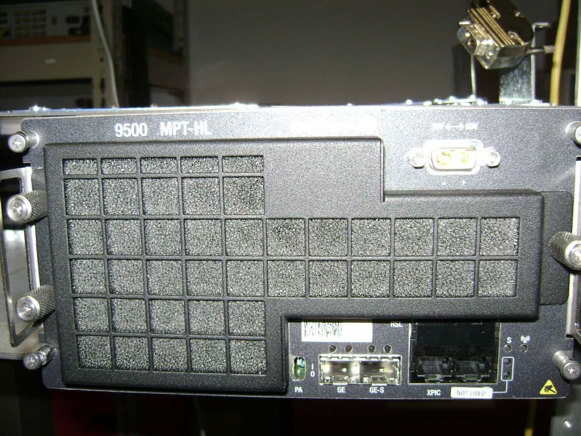
May 28, 20155 GHz rack-mounted point to point transceiver
Equipment Class
DTS - Digital Transmission System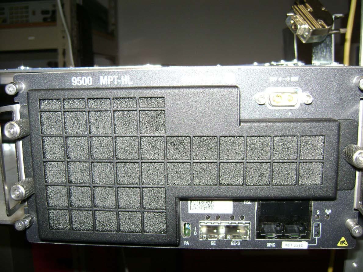
JF6-9558L
May 28, 20155 GHz rack-mounted point to point transceiver
Equipment Class
DTS - Digital Transmission System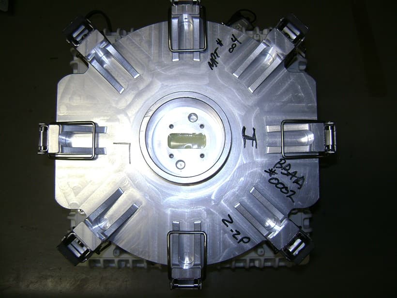
JF6-9558HC
Aug 06, 2012Microwave Packet Radio
Equipment Class
DTS - Digital Transmission System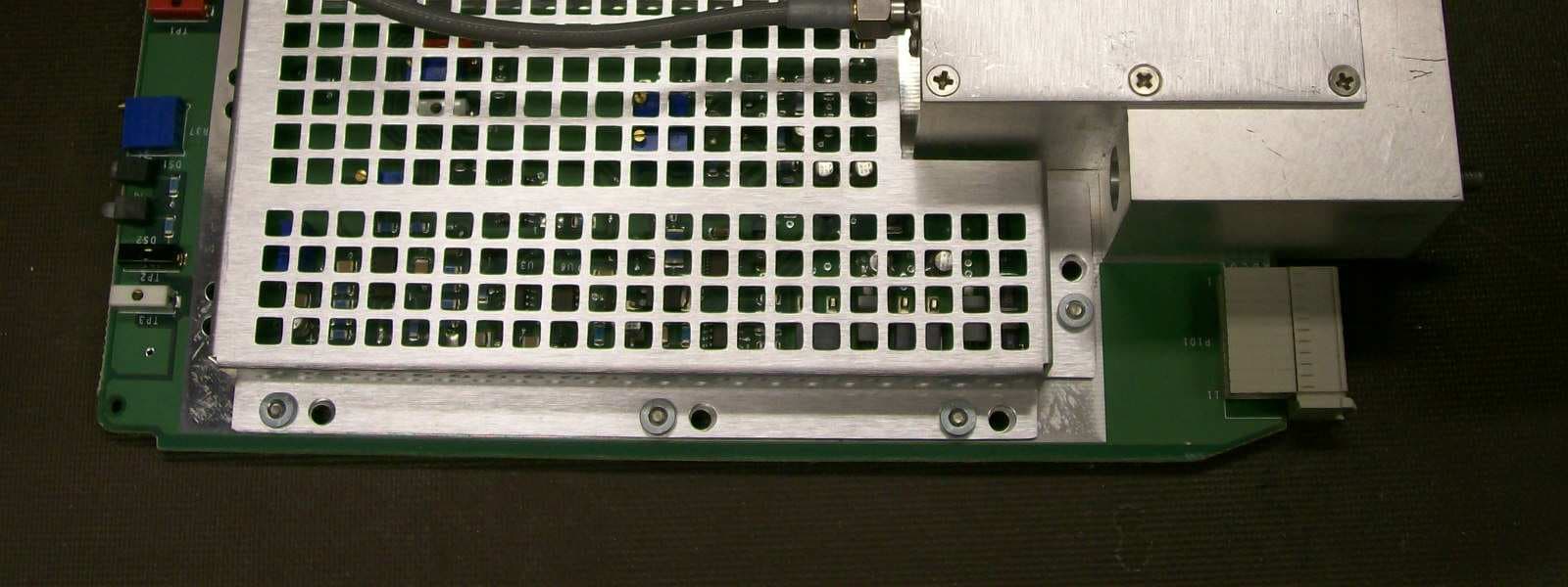
JF6-8702-50
Apr 26, 2010MDR-8000
Equipment Class
TNB - Licensed Non-Broadcast Station Transmitter
JF6-9558H
Jan 03, 2010MPT-HL Packet Terminal
Equipment Class
DTS - Digital Transmission System