JF6-9558HCMicrowave Packet Radio
Alcatel USA Marketing, Inc.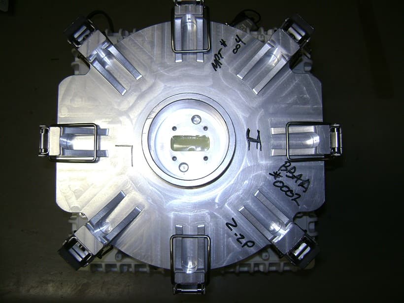
Click to zoom
Application Details
- Equipment Class
- DTS - Digital Transmission System
- Date of Grant
- Aug 06, 2012
- Application Purpose
- Original Equipment
- Date of Application
- Aug 06, 2012
- Equipment Note
- Microwave Packet Radio
- Frequency Range
- 5730.50000000 - 5844.50000000
- Company
- Alcatel USA Marketing, Inc.
- Country
- United States
Documents & Files
Document Text
Text extracted from the exhibit documents filed with the FCC. Open a document above to read the original.
Users Manual
PRELIMINARY Alcatel-Lucent 9500 MICROWAVE PACKET RADIO for ANSI | RELEASE 4.1.0 Indoor: MSS-8/MSS-4/MSS-1/MPT-HL Outdoor: ODU300/MPT-HC/MPT-XP/9558HC Product Information 3EM23952AL Edition 0.1 Alcatel-Lucent Proprietary This document contains proprietary information of Alcatel-Lucent and is not to be disclosed or used except in accordance with applicable agreements. Copyright 2012 © Alcatel-Lucent. All rights reserved. When printed by Alcatel-Lucent, this document is printed on recycled paper. Alcatel-Lucent assumes no responsibility for the accuracy of the information presented, which is subject to change without notice. Alcatel, Lucent, Alcatel-Lucent and the Alcatel-Lucent logo are trademarks of Alcatel-Lucent. All other trademarks are the property of their respective owners. Copyright 2012 Alcatel-Lucent. All rights reserved. Disclaimers Alcatel-Lucent products are intended for commercial uses. Without the appropriate network design engineering, they must not be sold, licensed or otherwise distributed for use in any hazardous environments requiring fail-safe performance, such as in the operation of nuclear facilities, aircraft navigation or communication systems, air traffic control, direct life-support machines, or weapons systems, in which the failure of products could lead directly to death, personal injury, or severe physical or environmental damage. The customer hereby agrees that the use, sale, license or other distribution of the products for any such application without the prior written consent of Alcatel-Lucent, shall be at the customer's sole risk. The customer hereby agrees to defend and hold Alcatel-Lucent harmless from any claims for loss, cost, damage, expense or liability that may arise out of or in connection with the use, sale, license or other distribution of the products in such applications. This document may contain information regarding the use and installation of non-Alcatel-Lucent products. Please note that this information is provided as a courtesy to assist you. While Alcatel-Lucent tries to ensure that this information accurately reflects information provided by the supplier, please refer to the materials provided with any non-Alcatel-Lucent product and contact the supplier for confirmation. Alcatel-Lucent assumes no responsibility or liability for incorrect or incomplete information provided about non-Alcatel-Lucent products. However, this does not constitute a representation or warranty. The warranties provided for Alcatel-Lucent products, if any, are set forth in contractual documentation entered into by Alcatel-Lucent and its customers. This document was originally written in English. If there is any conflict or inconsistency between the English version and any other version of a document, the English version shall prevail. © Alcatel-Lucent 2012 - All Rights Reserved Printed in U.S.A. THIS PRODUCT COMPLIES WITH D.H.H.S. RADIATION PERFORMANCE STANDARDS 21 CFR, 1040.10, FOR A CLASS 1 LASER PRODUCT. DANGER Invisible laser radiation is present when the optic connector is open. AVOID DIRECT EXPOSURE TO BEAM. WARNING This equipment has been tested and found to comply with the limits for a Class A digital device, pursuant to Part 15 of the FCC Rules. These limits are designed to provide reasonable protection against harmful interference when the equipment is operated in a commercial environment. This equipment generates, uses, and can radiate radio frequency energy and, if not installed and used in accordance with the instruction manual, may cause harmful interference to radio communications. Operation of this equipment in a residential area is likely to cause harmful interference in which case users will be required to correct the interference at their own expense. NOTICE This manual applies to 9500 MPR-A R4.1.0 software. Release notes describing revisions to this software may impact operations described in this manual. This transfer of commodities, technology, or software, if from the United States, is an export in accordance with the U.S. Export Administration Regulations. Diversion contrary to U.S. law is prohibited. The export or re-export (further transfer) of such commodities, technology, software or products made from such technology is prohibited without proper authorization(s) from the U.S. Department of Commerce or other appropriate U.S. government agency. All rights reserved. No part of this manual may be reproduced, translated, stored in a retrieval system, or transmitted or distributed by any means, electronic or mechanical, by photocopying, recording, or otherwise, without the written permission of Alcatel-Lucent. Preparing derivative works or providing instruction based on the material is prohibited unless agreed to in writing by Alcatel-Lucent. The product specification and/or performance levels contained in this document are for information purposes only and are subject to change without notice. They do not represent any obligation on the part of Alcatel-Lucent. Such obligations will only be committed to in a written sales agreement signed by Alcatel-Lucent. DOCUMENTATION Product documentation is available on Alcatel-Lucent’s OnLine Customer Support web site at https://support.alcatel-lucent.com/portal/olcsHome.do. To offer comments on this documentation, visit Alcatel-Lucent’s OnLine Customer Support web site at https://support.alcatel-lucent.com/portal/olcsHome.do and select Contact us, Customer support, and then OnLine Assistance or write to the following address. Alcatel-Lucent Attention: Doc Comment, M/S RND-1 3400 W. Plano Pkwy. Plano, Texas 75075-0811 USA 3EM23952AL Issue 0.1, November 2012 PRELIMINARY © Alcatel-Lucent 2012 - All Rights Reserved i ALCATEL-LUCENT PRACTICE Standard 9500 MPR-A Product Information Table of Contents FCC part 15 subpart B 1.9500 MPR-A unlicensed radio . . . . . . . . . . . . . . . . . . . . . . . . . . . . . . . . . . . . . . . . . 1-1 FCC Class B compliance statement. . . . . . . . . . . . . . . . . . . . …
Text truncated - open the document above for the full version.
Users Manual
PRELIMINARY 3EM23952AL Issue 0.1, November 2012 9500 MPR-A general system description 2-90 Protected cross plug-in L1 LAG sceneries 6.83In the Protected Cross Plug-in LAG configuration, the 1+1 protection group is seen as a single radio interface. The protected 1+1 HSB/SD radio configuration is created using the same SFP port on the left and right Plug-in, i.e. port 5 of the left P8ETH card (main) is protected by port 5 of the right P8ETH card (spare). 6.84Protected L1 LAG configurations are only supported using MPT-HL radio interfaces. 6.85An example of Protected Cross Plug-in LAG implementation is shown in Figure6-14. Site A is configured with two 1+1 HSB/SD protected radio links in a Protected Cross Plug-in LAG. Site B is configured with two Protected Cross Plug-in LAGs to implement a radio repeater configuration. Figure 6-13. 1+0 cross plug-in L1 LAG configurations—Update 3EM23952AL Issue 0.1, November 2012 PRELIMINARY 9500 MPR-A general system description 2-91 6.86In this configuration, radio protection handles a failure of a single radio hop belonging to the 1+1 HSB/SD protection group. LAG capacity is not affected by a single radio hop failure belonging to the protection group. 6.87Supported Protected Cross Plug-in L1 LAG 2x(1+1) configurations are shown in Figure6-15. Figure 6-14. Protected 1+1 cross plug-in L1 link aggregation scenario Update PRELIMINARY 3EM23952AL Issue 0.1, November 2012 9500 MPR-A general system description 2-92 6.88A mixture of protected and not protected L1 LAGs are supported. The protected pair can reside in any of the available P8ETH port pairs. Shown in Figure6-16 the protected pairs reside in ports 5 and 7. 6.89An extension of the supported protected Cross Plug-in configuration supports 3x(1+1) and 4x(1+1) as shown in Figure 6-17. Figure 6-15. Protected 2x(1+1) cross plug-in L1 LAG configurations—Update Figure 6-16. Mix 1+0 and 1+1 protected cross plug-in L1 LAG configurations—Update 3EM23952AL Issue 0.1, November 2012 PRELIMINARY 9500 MPR-A general system description 2-93 L1 LAG creation 6.90L1 LAG is created using the following parameters: •LAG ID (LAG Identifier): is mandatory parameter that identifies the LAG in the NE •LAG Name: is an optional parameter which assist the operator to identify the virtual radio direction. LAG Name is up to 32 characters in length. •LAG Type: is a mandatory parameter that defines the LAG type (i.e., L1 Radio, L2 Radio, L2 Ethernet). •LAG Size: is a mandatory parameter that configures the maximum number of radio links included in the L1 LAG. LAG Size cannot be lower than the number of radio links belonging to the LAG. •Administrative Status: indicates the operational status of the LAG and is configured by the operator 6.91LAG ID is selected with the following restrictions: •integer from 1 to 14 •cannot be same as LAG ID of an existing L1/L2 LAG ID •cannot be equal to the Administrative Key of an existing L2 LAG Figure 6-17. Protected 3x(1+1)/4x(1+1) cross plug-in L1 LAG configurations—Update PRELIMINARY 3EM23952AL Issue 0.1, November 2012 9500 MPR-A general system description 2-94 6.92When the administrative state of the LAG is disabled, no traffic is sent out the LAG. No LAG alarms are reported to the WebEML. 6.93When the administrative state of the LAG is enabled, the LAG is available for the following: •cross-connections •802.1Q port membership •selected as synchronization reference 6.94A LAG cannot be disabled when involved in any of the following: •cross-connections •802.1Q port membership •selected as synchronization reference 6.95The following features are supported at the L1 LAG level: •Wait-To-Restore (WTR) •PPP RF •SSM 6.96A Wait-To-Restore timer provides a mechanism to minimize the impact to LAG capacity by fast/intermittent failures on a radio link member of the LAG. WTR time is configurable from 100 milliseconds to 8 seconds. The default value is 1 second. 6.97When a radio link member of a LAG declares a traffic affecting condition, that member is removed from the available radio links and the capacity of the LAG is reduced accordingly. Once the failure condition is cleared, the WTR period is applied. Upon expiration of the WTR period, if the radio link remains condition free, the radio link is restored as a member of the LAG and becomes available to carry traffic. The capacity of the LAG is increased accordingly. 6.98The following LAG parameters can be modified after creation: •Port membership •LAG Name 3EM23952AL Issue 0.1, November 2012 PRELIMINARY 9500 MPR-A general system description 2-95 •LAG Size •Wait to Restore time L1 LAG lowest index port 6.99A LAG Lowest Index Port is defined for each LAG. The Lowest index Port is responsible to transmit traffic from the Distributor (near end) towards the Collector (far end) and vice versa. 6.100Lowest index Port is selected from P8ETH SFP ports 5 or 7 depending on LAG configuration scenario. 6.101Lowest index Port is configured using the following: •Intra Plug-in –Port 5 or Port 7 –Lowest index Port shall have the lowest index in the LAG port membership (i.e., if Lowest index Port is Port 7, Port 5 and/or Port 6 cannot be added to the LAG). –one Lowest index Port per LAG •Cross Plug-in –port 5 or port 7 on both P8ETH configured in LAG –Lowest index Ports shall have the lowest index in the LAG port membership (i.e., if Lowest Index Port is port 7, port 5 or port 6 cannot be added to the LAG). –one lowest index port is main (active) –one lowest index port is spare (standby) 6.102For Intra Plug-in LAG, the active lowest index port is configured on the P8ETH hosting LAG. 6.103For Cross Plug-in LAG, the active lowest index port is configured: –left P8ETH (slots 3, 5, or 7) port 5 when available –right P8ETH (slots 4, 6, or 8) port 7 when available PRELIMINARY 3EM23952AL Issue 0.1, November 2012 9500 MPR-A general system description 2-96 6.104When a mixture of Intra/Cross Plug-in LAGs are configured on the same row, the active lowest index port of the Cross Plug-in L…
Text truncated - open the document above for the full version.
Users Manual
PRELIMINARY 3EM23952AL Issue 0.1, November 2012 9500 MPR-A general system description 2-206 6.695This loopback requires an external Tx to Rx connection to guarantee operation. 6.696This loopback is traffic affecting. Line facing PDH (DS1/DS3) loopback 6.697Line facing PDH loopback is a local loopback which loops the receive line signal (from the line) onto the transmit signal (towards the Line). This loopback type is shown in Figure6-62. 6.698This loopback is drop and continue. 6.699This loopback is configured using the Craft Terminal. Radio facing PDH (DS1/DS3) loopback 6.700Radio facing PDH loopback is a remote loopback which loops the receive tributary signal (from the Core) onto the transmit signal (towards the Core). This loopback type is shown in Figure6-62. 6.701This loopback may be activated for each DS1/DS3 tributary port. 6.702This loopback is loop and continue. 6.703This loopback is configured using the Craft Terminal. Loopback time-out 6.704The system supports a loopback time-out mechanism to avoid the risk of a permanent disconnection from the Craft Terminal to a remote NE after executing a loopback. 6.705The time--out period is entered into the management system expressed in days/hours/minutes. 6.706The maximum time-out period is 4 days. 6.707The default time-out period is 5 minutes Figure 6-62. Core and Line Facing PDH Loopback 3EM23952AL Issue 0.1, November 2012 PRELIMINARY 9500 MPR-A general system description 2-207 Loopback activation 6.708Loopbacks can be activated by local or remote management systems. The activation command includes the duration of the loopback (time-out). 6.709Core facing and Radio facing loopbacks are not supported at the same time. 6.710The time-out period starts at the activation time and expires at the end of the time-out period. 6.711The operator has the option to deactivate the loopback during the activation period. 6.712The operator also has the option to extend the time-out period during the activation period. In this case, the time-out period is re-initiated. The specified time period starts over from the new activation date, overwriting the previous activation date and time-out values. Network Management 6.713The system supports the following network managers: •Alcatel-Lucent 1350 OMS •Alcatel-Lucent 1352 CM (Compact Manager) •Alcatel-Lucent 1353 NM •Alcatel-Lucent 5620 SAM Performance monitoring 6.714Performance Monitoring (PM) is supported by the system. PM is performed through the PM Tool. PM data is collected in 15 minute and 24 hour time periods. PM counters the system supports are described in the following paragraphs. Ethernet user port PM 6.715PM of the Ethernet physical interface statistics related to the Tx and Rx packets are supported on all user Ethernet interfaces. The available Ethernet PM counters are: PRELIMINARY 3EM23952AL Issue 0.1, November 2012 9500 MPR-A general system description 2-208 •Total Number of Tx Packets •Total Number of Tx Bytes •Total Number of Tx Discarded Packets •Total Number of Tx Unicast Packets •Total Number of Tx Broadcast Packets •Total Number of Tx Multicast Packets •Total Number of Rx Packets •Total Number of Rx Bytes •Total Number of Rx Discarded Packets •Total Number of Rx Unicast Packets •Total Number of Rx Broadcast Packets •Total Number of Rx Multicast Packets •Total Number of Rx Errored Packets Adaptive modulation PM 6.716PM of the Tx modulation scheme is monitored when adaptive modulation is enabled. For 1+1 HSB radio configurations, the statistics are related to the active radio channel. PM tracks the amount of time elapsed in each modulation technique. L1 radio LAG ethernet port PM 6.717PM of the L1 Radio LAG Ethernet port statistics related to the Tx packets are supported on all L1 Radio LAG Ethernet ports. The available Ethernet PM counters are: •Total Transmitted Octets (TTO)—Equals the number of good transmitted Octets on the port •Total Transmitted Frames (TTF)—Equals the total number of good transmitted frames on the port •Total Discarded Frames (TDF)—Equals the number of transmitted frames discarded on the port 3EM23952AL Issue 0.1, November 2012 PRELIMINARY 9500 MPR-A general system description 2-209 •Available Capacity—Equals the available capacity of the L1 radio LAG Lowest Index Port •Used Capacity—Equals the ratio of TTF to Capacity of the L1 radio LAG Ethernet flow •TTO Throughput—Equals the TTO Throughput of the L1 radio LAG Ethernet flow •TDF Ratio—Equals the ratio of TDF to TTF of the L1 radio LAG Ethernet flow Radio analog PM 6.718PM of the local analog Tx and Rx power levels are supported on MPT- HC and ODU300. PM counters are available for each radio hop and link (in 1+1 Rx side only). The available radio analog PM counters are: •Tx Minimum Power Level •Tx Maximum Power Level •Tx Average Power Level •Rx Minimum Power Level •Rx Maximum Power Level •Rx Average Power Level Radio ethernet PM 6.719PM of the radio Ethernet statistics related to the Tx radio link are supported for each radio direction. The available Radio Ethernet PM counters are: •Total Number of Tx Packets •Total Number of Tx Bytes •Total Number of Tx Discarded Packets Radio hop PM 6.720PM of the radio hop section (before radio protection switching) is supported for each radio hop. The available Radio hop PM counters are: •Errored Seconds (ES) PRELIMINARY 3EM23952AL Issue 0.1, November 2012 9500 MPR-A general system description 2-210 •Severely Errored Seconds (SES) •Background Block Errors (BBE) •Unavailable Seconds (UAS). Radio link PM 6.721PM of the protected radio channel (after radio protection switching) is supported for each radio link. The available Radio link PM counters are: •Errored Seconds (ES) •Severely Errored Seconds (SES) •Background Block Errors (BBE) •Unavailable Seconds (UAS). Radio QoS PM 6.722PM of the radio QoS queues (queues 1 to 5) related to Ethernet traffic for each radio direction are supported. The available Radio Qos PM counters are: •Number of Tx Packets •Number of Tx Bytes •Numb…
Text truncated - open the document above for the full version.
Users Manual
PRELIMINARY 3EM23952AL Issue 0.1, November 2012 9500 MPR-A general system description 2-314 Table 7-L. Radio profiles: MPT-HC, static modulation CHANNEL FREQUENCY MODULATION SCHEME BANDWIDTH / MAXIMUM DATA PAYLOAD CAPACITY 5 MHz10 MHz30 MHz40 MHZ50 MHz Unlicensed4 QAM14.02 Mbps43.85 Mbps 8PSK21.13 Mbps66.50 Mbps 16 QAM28.27 Mbps87.45 Mbps 32 QAM35.23 Mbps108.75 Mbps 64 QAM44.73 Mbps138.02 Mbps 128 QAM24.36 Mbps52.69 Mbps162.88 Mbps 256 QAM60.30 Mbps185.37 Mbps Lower 6 GHz4QAM43.85 Mbps 16QAM87.45 Mbps 32QAM108.75. Mbps 64QAM138.02 Mbps 128QAM52.69 Mbps162.88 Mbps 256QAM60.30 Mbps185.37 Mbps Upper 6 GHz4QAM14.02 Mbps43.85 Mbps 8PSK21.13 Mbps66.50 Mbps 16QAM28.27 Mbps87.45 Mbps 32QAM35.23 Mbps108.75. Mbps 64QAM44.73 Mbps138.02 Mbps 128QAM52.69 Mbps162.88 Mbps 256QAM60.30 Mbps185.37 Mbps 7/8 GHz4QAM14.02 Mbps43.85 Mbps 8PSK21.13 Mbps66.50 Mbps 16QAM28.27 Mbps87.45 Mbps 32QAM35.23 Mbps108.75 Mbps 64QAM44.73 Mbps138.02 Mbps 128QAM52.69 Mbps162.88 Mbps 256QAM60.30 Mbps185.37 Mbps 11 GHz64QAM44.73 Mbps138.02 Mbps186.97 Mbps 128QAM52.69 Mbps162.88 Mbps220.63 Mbps 256QAM60.30 Mbps185.37 Mbps251.09 Mbps 3EM23952AL Issue 0.1, November 2012 PRELIMINARY 9500 MPR-A general system description 2-315 15 GHz4QAM43.85 Mbps59.48 Mbps74.59 Mbps 64QAM44.73 Mbps138.02 Mbps186.978 Mbps234.22 Mbps 128QAM52.69 Mbps162.88 Mbps220.63 Mbps276.37 Mbps 256QAM60.30 Mbps185.37 Mbps251.09 Mbps314.46 Mbps 18 GHz4QAM14.02 Mbps43.85 Mbps59.48 Mbps74.59 Mbps 8PSK21.13 Mbps65.50 Mbps88.81 Mbps111.29 Mbps 16QAM28.27 Mbps87.45 Mbps118.51 Mbps148.49 Mbps 32QAM35.23 Mbps108.75 Mbps147.36 Mbps184.60 Mbps 64QAM44.74 Mbps138.02 Mbps186.97 Mbps234.22 Mbps 128QAM52.70 Mbps162.88 Mbps220.63 Mbps276.37 Mbps 256QAM60.31 Mbps185.37 Mbps251.09 Mbps314.46 Mbps 23 GHz64QAM44.73 Mbps138.02 Mbps186.97 Mbps234.22 Mbps 128QAM52.69 Mbps162.88 Mbps220.63 Mbps276.37 Mbps 256QAM60.30 Mbps185.37 Mbps251.09 Mbps314.46 Mbps 38 GHz4QAM43.85 Mbps59.48 Mbps74.59 Mbps 16QAM87.45 Mbps 32QAM108.75 Mbps 64QAM44.73 Mbps138.02 Mbps186.97 Mbps234.22 Mbps 128QAM52.69 Mbps162.88 Mbps220.63 Mbps276.37 Mbps 256QAM60.30 Mbps185.37 Mbps251.09 Mbps314.46 Mbps Table 7-M. Radio profiles: MPT-HC, high gain static modulation CHANNEL FREQUENCY MODULATION SCHEME BANDWIDTH / MAXIMUM DATA PAYLOAD CAPACITY 40 MHz50 MHZ 11 GHz256QAM220 Mbps 15 GHz256QAM220 Mbps 18 GHz256QAM220 Mbps276 Mbps 23 GHz256QAM220 Mbps276 Mbps 38 GHz256QAM220 Mbps276 Mbps Table 7-L. Radio profiles: MPT-HC, static modulation (cont.) CHANNEL FREQUENCY MODULATION SCHEME BANDWIDTH / MAXIMUM DATA PAYLOAD CAPACITY 5 MHz10 MHz30 MHz40 MHZ50 MHz PRELIMINARY 3EM23952AL Issue 0.1, November 2012 9500 MPR-A general system description 2-316 Table 7-N. Radio profiles: MPT-HC, XPIC, static modulation CHANNEL FREQUENCY MODULATION SCHEME BANDWIDTH / DATA PAYLOAD CAPACITY 30 MHz40 MHz50 MHz Lower 6 GHz128QAM162.88 Mbps 256QAM185.37 Mbps Upper 6 GHz128QAM162.88 Mbps 256QAM185.37 Mbps 7/8 GHz128QAM162.88 Mbps 256QAM185.37 Mbps 11 GHz128QAM162.88 Mbps220.63 Mbps 256QAM185.37 Mbps251.09 Mbps 15 GHz128QAM162.88 Mbps220.63 Mbps276.37 Mbps 256QAM185.37 Mbps251.10 Mbps314.46 Mbps 18 GHz128QAM162.88 Mbps220.63 Mbps276.37 Mbps 256QAM185.37 Mbps251.09 Mbps314.46 Mbps 23 GHz128QAM162.88 Mbps220.63 Mbps276.37 Mbps 256QAM185.37 Mbps251.09 Mbps314.46 Mbps 38 GHz128QAM162.88 Mbps220.63 Mbps276.37 Mbps 256QAM185.37 Mbps251.09 Mbps314.46 Mbps Table 7-O. Radio profiles: MPT-HC, high gain, XPIC, static modulation CHANNEL FREQUENCY MODULATION SCHEME BANDWIDTH / MAXIMUM DATA PAYLOAD CAPACITY 40 MHz50 MHZ 11 GHz256QAM220 Mbps 15 GHz256QAM220 Mbps 18 GHz256QAM220 Mbps276 Mbps 23 GHz256QAM220 Mbps276 Mbps 38 GHz256QAM220 Mbps276 Mbps 3EM23952AL Issue 0.1, November 2012 PRELIMINARY 9500 MPR-A general system description 2-317 Table 7-P. Radio profiles: MPT-HC, adaptive modulation CHANNEL FREQUENCY MODULATION SCHEME BANDWIDTH / DATA PAYLOAD CAPACITY 5 MHz10 MHz30 MHz40 MHz50 MHz Unlicensed4 QAM6.33 Mbps14.02 Mbps43.85 Mbps 8PSK9.69 Mbps21.13 Mbps66.50 Mbps 16 QAM13.03 Mbps28.27 Mbps87.45 Mbps 32 QAM16.13 Mbps35.23 Mbps108.75 Mbps 64 QAM20.58 Mbps44.73 Mbps138.02 Mbps 128 QAM24.36 Mbps52.69 Mbps162.88 Mbps 256 QAM60.30 Mbps185.37 Mbps Lower 6 GHz 4QAM 1 43.85 Mbps 16QAM 1 87.45 Mbps 32QAM 1 108.75 Mbps 64QAM138.02 Mbps 128QAM162.88 Mbps 256QAM185.37 Mbps Upper 6 GHz 4QAM 1 14.02 Mbps43.85 Mbps 8PSK 1 21.13 Mbps66.50 Mbps 16QAM 1 28.27 Mbps87.45 Mbps 32QAM 1 35.23 Mbps108.75 Mbps 64QAM44.73 Mbps138.02 Mbps 128QAM52.69 Mbps162.88 Mbps 256QAM60.30 Mbps185.37 Mbps 7/8 GHz4QAM14.02 Mbps43.85 Mbps 8PSK21.13 Mbps66.50 Mbps 16QAM28.27 Mbps87.45 Mbps 32QAM35.23 Mbps108.75 Mbps 64QAM44.73 Mbps138.02 Mbps 128QAM52.69 Mbps162.88 Mbps 256QAM60.30 Mbps185.37 Mbps 11 GHz 4QAM 1 43.85 Mbps59.48 Mbps74.59 Mbps 64QAM138.02 Mbps186.97 Mbps234.22 Mbps 128QAM162.88 Mbps220.63 Mbps276.37 Mbps 256QAM185.37 Mbps251.09 Mbps314.46 Mbps PRELIMINARY 3EM23952AL Issue 0.1, November 2012 9500 MPR-A general system description 2-318 15 GHz4QAM43.85 Mbps59.48 Mbps74.59 Mbps 64QAM44.73 Mbps138.02 Mbps186.98 Mbps234.23 Mbps 128QAM52.69 Mbps162.88 Mbps220.63 Mbps276.37 Mbps 256QAM60.30 Mbps185.37 Mbps251.09 Mbps314.46 Mbps 18 GHz4QAM14.02 Mbps43.85 Mbps59.48 Mbps74.59 Mbps 8PSK21.13 Mbps65.50 Mbps88.81 Mbps111.29 Mbps 16QAM28.27 Mbps87.45 Mbps118.51 Mbps148.49 Mbps 32QAM35.23 Mbps108.75 Mbps147.36 Mbps184.60 Mbps 64QAM44.73 Mbps138.02 Mbps186.97 Mbps234.22 Mbps 128QAM52.69 Mbps162.88 Mbps220.63 Mbps276.37 Mbps 256QAM60.30 Mbps185.37 Mbps251.09 Mbps314.46 Mbps 23 GHz4QAM43.85 Mbps59.48 Mbps74.59 Mbps 64QAM138.02 Mbps186.97 Mbps234.22 Mbps 128QAM162.88 Mbps220.63 Mbps276.37 Mbps 256QAM185.37 Mbps251.09 Mbps314.46 Mbps 38 GHz4QAM43.85 Mbps59.48 Mbps74.59 Mbps 16QAM87.45 Mbps 32QAM108.75 Mbps 64QAM138.02 Mbps186.97 Mbps234.22 Mbps 128QAM162.88 Mbps220.63 Mbps276.37 Mbps 256QAM185.37 Mbps251.09 Mbps314.46 Mbps [1] Subject to FCC Part 101 Rules. Table 7-Q. Radio profiles: MPT-HC, XPIC, adaptive modulation CHANNEL FREQUENCY MODULATION SCHEME BANDWIDTH / DATA PAYLOAD CAPACITY 30 MHz40 MHz50 MHz…
Text truncated - open the document above for the full version.
Users Manual
3EM23952AL Issue 0.1, November 2012 PRELIMINARY DS1 RJ-45 Patch Panel 3-92 UDS-113 Connectors Refer to Table113-A for DS1 RJ-45 Patch Panel connector details. Figure 113-2. DS1 RJ-45 patch panel (rear view) Table 113-A. P32E1DS1 DS1 card front panel connector details CONNECTORTYPEFUNCTION I/O (1- 32)RJ-45DS1, Tx and Rx (tip and ring), interconnect DS1s number 1 through 32 M164 position SCSI connector DS1, Tx and Rx (tip and ring), interconnect DS1s number 1 through 16, Main M264 position SCSI connector DS1, Tx and Rx (tip and ring), interconnect DS1s number 17 through 32, Main M364 position SCSI connector DS1, Tx and Rx (tip and ring), interconnect DS1s number 1 through 16, Spare M464 position SCSI connector DS1, Tx and Rx (tip and ring), interconnect DS1s number 17 through 32, Spare 950-0118-1 071710 RJ-45 DS1 Patch Panel Rear View UDS-114 3EM23952AL Issue 0.1, November 2012 PRELIMINARY Type N adapter bracket 3-93 UDS-114 Type N adapter bracket Features and application notes •Provides mechanical mounting location for three MOD300 IF jumper cables to transition MOD300 card SMA connector to Type N female connector. Description The Type N Adapter Bracket mounts on either the left and/or right side of the rack. May be mounted above and/or below the MSS-8 shelf. See Figure114-1 for a front view of the Type N Adapter Bracket. See Figure114-2 for Type N Adapter Bracket dimensions. PART NUMBER/ MNEMONIC NAMECLEIECI/ BAR CODE CPRSTATUS 3EM23272AAType N Adapter BracketN/AN/AN/AActive Figure 114-1. Type N adapter bracket (front view) 950-0116-1 071610 Type N Adapter Brackets May be Mounted above MSS-8 Shelf 3EM23952AL Issue 0.1, November 2012 PRELIMINARY Type N adapter bracket 3-94 UDS-114 Figure 114-2. Type N adapter bracket dimensions 950-0115-1 071610 1.72 6.10 1.73 1.770 1.770 UDS-115 3EM23952AL Issue 0.1, November 2012 PRELIMINARY DS1 d-connector patch panel 3-95 UDS-115 DS1 d-connector patch panel Features and application notes •Converts P32E1DS1 card SCSI connectors to four 37 position DSUB connectors. •Supports both protected and non-protected P32E1DS1 applications. •Requires two 68 pin SCSI cables in non-protected DS1 configuration. Requires four 68 pin SCSI cables in protected DS1 configuration. Description The DS1 D-Connector Patch Panel mounts above and/or below the MSS-8 shelf. Requires 1 rack increments. Customer interconnect are the four 37 position DSUB connectors. Each 37 position DSUB connector supports eight DS1 signals. Four 68 pin SCSI connectors interconnects the main and spare P32E1DS1 card connectors. See Figure115-1 for a front view of the DS1 D-Connector Patch Panel. See Figure115-2 for a rear view of the DS1 D-Connector Patch Panel. PART NUMBER/ MNEMONIC NAMECLEIECI/ BAR CODE CPRSTATUS 3DB16102AADS1 D-Connector Patch Panel N/AN/AN/AActive Figure 115-1. DS1 RJ-45 patch panel (front view) 950-0119-1 071710 37 Pin DSUB DS1 Patch Panel Front View E1/DS1-17/24 E1/DS1-25/32E1/DS1-9/16 E1/DS1-1/8 3EM23952AL Issue 0.1, November 2012 PRELIMINARY DS1 d-connector patch panel 3-96 UDS-115 Connectors Refer to Table115-A for DS1 D-Connector Patch Panel connector details. Figure 115-2. DS1 RJ-45 patch panel (rear view) Table 115-A. P32E1DS1 DS1 card front panel connector details CONNECTORTYPEFUNCTION E1/DS1 - 1/837 position DSUB connector DS1, Tx and Rx (tip and ring), Customer Interconnect DS1s number 1 through 8 E1/DS1 - 9/1637 position DSUB connector DS1, Tx and Rx (tip and ring), Customer Interconnect DS1s number 9 through 16 E1/DS1 - 17/2437 position DSUB connector DS1, Tx and Rx (tip and ring), Customer Interconnect DS1s number 17 through 24 E1/DS1 - 25/3237 position DSUB connector DS1, Tx and Rx (tip and ring), Customer Interconnect DS1s number 25 through 32 E1/DS1 - 1/16 Main64 position SCSI connector DS1, Tx and Rx (tip and ring), P32E1DS1 Interconnect DS1s number 1 through 16, Main E1/DS1 - 17/32 Main64 position SCSI connector DS1, Tx and Rx (tip and ring), P32E1DS1 Interconnect DS1s number 17 through 32, Main E1/DS1 - 1/16 Spare64 position SCSI connector DS1, Tx and Rx (tip and ring), P32E1DS1 Interconnect DS1s number 1 through 16, Spare E1/DS1 - 17/32 Spare64 position SCSI connector DS1, Tx and Rx (tip and ring), P32E1DS1 Interconnect DS1s number 17 through 32, Spare 950-0120-1 071710 37 Pin DSUB DS1 Patch Panel Rear View E1/DS1-1/16 EXT E1/DS1-1/16 MAIN E1/DS1-17/32 MAIN E1/DS1-7/32 EXT UDS-116 3EM23952AL Issue 0.1, November 2012 PRELIMINARY 3 dB hybrid splitter 3-97 UDS-116 3 dB hybrid splitter Description External 3 dB hybrid splitter used to interconnect protected DS3 signals. Connectors Refer to Table116-A for DS3 Hybrid Splitter connector details. ADD DS3 PATCH PANEL DETAILS.. PART NUMBER/ MNEMONIC NAMECLEIECI/ BAR CODE CPRSTATUS 3EM24462AADS3 Patch PanelN/AN/AN/AActive 3EM22900AADS3 Hybrid SplitterN/AN/AN/AActive Figure 116-1. Hybrid splitter interconnect 950-0201-1 022610 Spare Side Mini BNC Connectors S LINE 2 IN OUT LINE 1 IN OUT 9500 MPR DS3 Trib (Protected Pair) MSS-8 Shelf Main Side Mini BNC Connectors LINE 2 IN OUT LINE 1 IN OUT S P2E3DS3P2E3DS3 BNC Panel Mount Customer Connectors Line 1 Out Line 1 In Line 2 Out Line 2 In 3EM23952AL Issue 0.1, November 2012 PRELIMINARY 3 dB hybrid splitter 3-98 UDS-116 Table 116-A. Hybrid splitter connector detail CONNECTORTYPEFUNCTION Customer Interconnect75 ohm BNC, Female Protected DS3 customer interconnect, input and output. P2E3DS3 Card Interconnect 75 ohm male, mini-BNC Protected DS3 P2E3DS3 Card interconnect, input and output. UDS-117 3EM23952AL Issue 0.1, November 2012 PRELIMINARY MSS-4 microwave service switch shelf 3-99 UDS-117 MSS-4 microwave service switch shelf Features and application notes •The Microwave Service Switch (MSS-4) shelf provides cross- connection, port aggregation, switching, and equipment management. •10Gb Packet Based Node •300 Mbps full-duplex Ethernet transport capacity •Flexible aggregate capacity sharing DS1, DS3, and Ethernet traffic •Split mount configuration utilizing the MOD300 radio cards…
Text truncated - open the document above for the full version.
Contact Information
Applicant
Alfred Holland(R&D Manager)
Technical Contact
Alcatel USA Marketing Inc.Duane Mortensen
[email protected]972-477-8273
3400 W. Plano Parkway · Plano · United States
Non-Technical Contact
Nemko USA, Inc.Zarah G. MacIvor
[email protected]214-629-5683
Test Firm
Nemko USA, Inc. - San Diego EMC DivisionJan Blomgren
[email protected]760-444-3500
Technical Specifications
| # | Rule Parts | Frequency Range | Power Output |
|---|---|---|---|
| 1 | 15C | 5.73 GHz - 5.84 GHz | 1 W |
Other Applications from Alcatel USA Marketing, Inc.
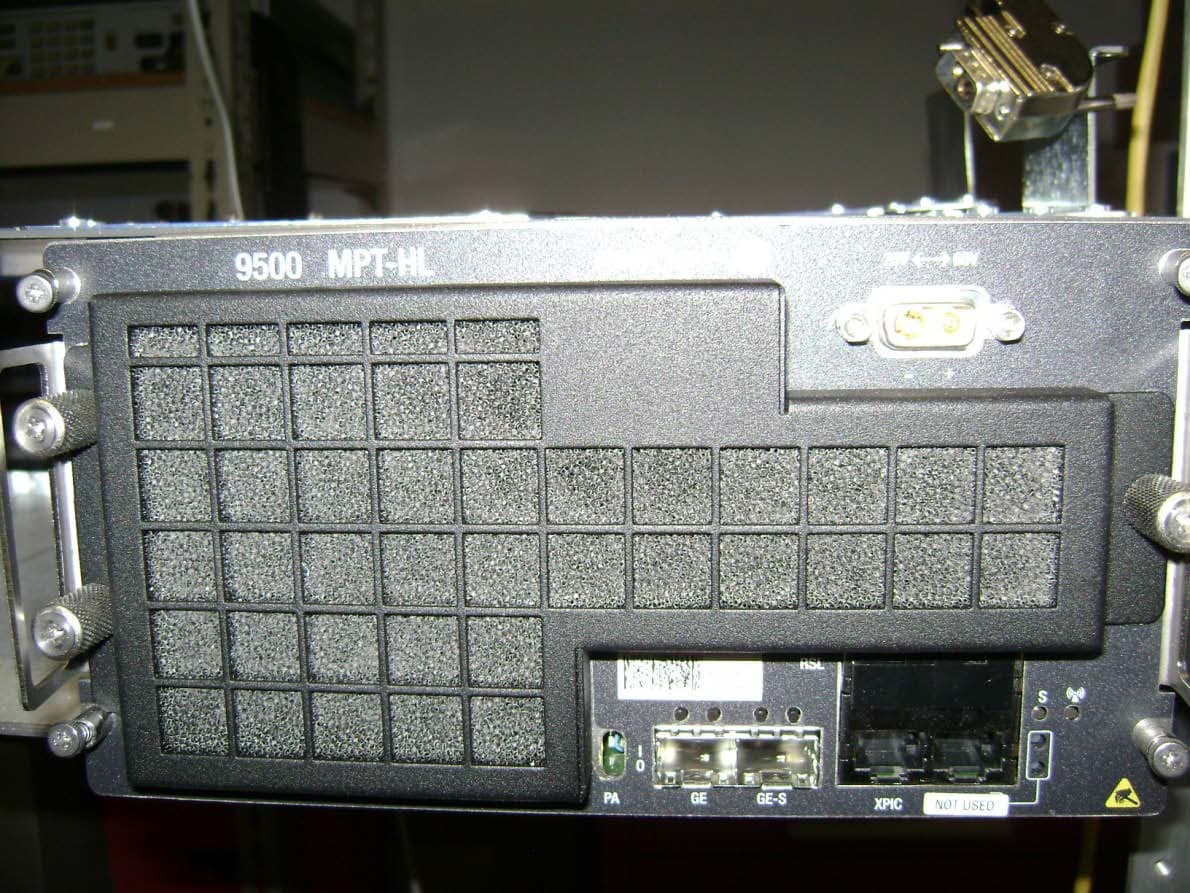
JF6-9558L-D
May 28, 20155 GHz rack-mounted point to point transceiver
Equipment Class
DTS - Digital Transmission System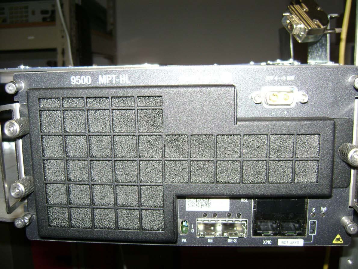
JF6-9558L
May 28, 20155 GHz rack-mounted point to point transceiver
Equipment Class
DTS - Digital Transmission System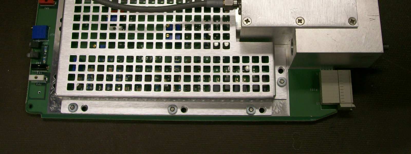
JF6-8702-50
Apr 26, 2010MDR-8000
Equipment Class
TNB - Licensed Non-Broadcast Station Transmitter
JF6-9558H
Jan 03, 2010MPT-HL Packet Terminal
Equipment Class
DTS - Digital Transmission System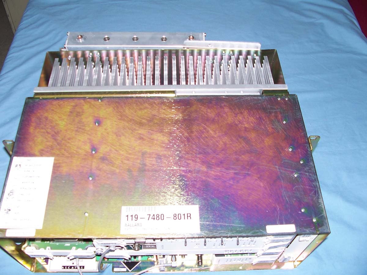
JF6-8000-2U
Oct 24, 2006Digital Transmission System Transmitter
Equipment Class
DTS - Digital Transmission System