JF6-8702-50MDR-8000
Alcatel USA Marketing, Inc.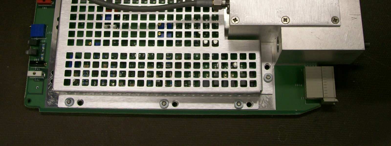
Click to zoom
Application Details
- Equipment Class
- TNB - Licensed Non-Broadcast Station Transmitter
- Date of Grant
- Apr 26, 2010
- Application Purpose
- Original Equipment
- Date of Application
- Apr 20, 2010
- Equipment Note
- MDR-8000
- Frequency Range
- 2345.00000000 - 2360.00000000
- Company
- Alcatel USA Marketing, Inc.
- Country
- United States
Documents & Files
Document Text
Text extracted from the exhibit documents filed with the FCC. Open a document above to read the original.
Users Manual
MDR-8000 Alcatel Part Number 3EM11931AA 3400 West Plano Parkway Plano, Texas 75075-5813 U.S.A. Issue 9, December, 2007 Microwave Digital Radios Users Manual NORTH AMERICA CUSTOMER SERVICE CENTER 24 HOURS PER DAY, 7 DAYS PER WEEK PHONE the Call Center at 888-252-2832 (US and Canada) or 613-784-6100 (International) ALCATEL-LUCENT’S PRIMARY MISSION IS SATISFYING OUR CUSTOMERS' QUALITY EXPECTATIONS. The Call Center Agent (CSA) Will help connect you with Technical Assistance (TAC) Or assist you with a Repair and Return • Phone-based technical support • After-hour emergencies • On-site technical support • E-mail support [email protected] • Software and hardware upgrades TAC • Module repair Repair and Return • Training http://www.alcatel-lucent.com>support – Technical Training Other Services Offered • Field Services – Installation and test • Customized and Comprehensive Service Agreements • Registration http://www.alcatel-lucent.com>MyAccess – Once registered – From “MyAlcatel” go to “Alcatel Support Documentation” – Register for access to Documentation and e-mail Update notifications For Product Change Notices (PCN), Product Documentations, etc. – Software and Hardware upgrade documentation Telephone Assistance, Normal Working Hours (CST 8am 5pm M-F) TAC supports all Alcatel North America Microwave products. This includes routine questions and emergency service. Telephone Assistance, Emergency After-Hours • Defined as loss of traffic, standby equipment, or network visibility on traffic-bearing systems. • Available through our Customer Service Agents (CSA). Contact Information Ask the Customer Service Agent (CSA) for a Microwave (MW) or a Network Management Service engineer (NMS). Please provide the following information to the Customer Service Agent (CSA): • Last and First name • Company name • Telephone number • City and state (Street address if applicable) or Site Name and Location • Equipment type • A brief description of the problem affecting their equipment • Customer Priority: High, Medium, or Low. • TL-9000 Severity as described below. Creating a TAC Action Request (AR) Critical TL-9000 Severities Defined Major Minor Problems not classified as critical or major. Problems severely affecting service, traffic, capacity, or network management. They require immediate corrective action. (Ex. Loss of network management capability, loss of traffic imminent or existing). Conditions seriously affecting system operation. They require immediate attention. (Ex. processor outage, loss of standby equipment, loss of remote access, or network managers). TAC Technical Assistance Center T able of Contents TOC - 1 Page Section 1 General 1.1 INTRODUCTION ............................................................................................. 1 - 1 1.2 CONTENT ....................................................................................................... 1 - 1 Section 2 Operation 2.1 GENERAL ........................................................................................................ 2 - 1 2.2 TURN-ON ........................................................................................................ 2 - 1 2.3 USER SYSTEM INTERFACE (USI) PROVISIONING FUNCTION/OPERATION ...... 2 - 2 2.4 OPERATING PROCEDURES .............................................................................. 2 - 2 2.4.1 Radio Receiver Manual Switching ..................................................................... 2 - 2 2.4.2 Radio Transmitter Manual Switching ................................................................. 2 - 5 2.4.3 Radio I/O Interface Manual Switching .............................................................. 2 - 5 2.4.4 MCS-11 Operation .......................................................................................... 2 - 7 2.4.5 Lamp Tests ....................................................................................................... 2 - 8 2.4.6 Alarm Checks .................................................................................................. 2 - 8 2.4.7 Orderwire Operation ....................................................................................... 2 - 8 2.4.8 Initiating Outgoing Orderwire Calls .................................................................. 2 - 8 2.4.9 Answering Incoming Orderwire Calls ................................................................ 2 - 8 2.5 TURN-OFF PROCEDURE ................................................................................... 2 - 9 2.6 EMERGENCY OPERATION .............................................................................. 2 - 9 2.7 MODEM OPERATION ...................................................................................... 2 - 9 2.8 CONTROLS, INDICATORS, TEST POINTS, AND CONNECTORS ....................... 2 - 9 Section 3 Interconnect 3.1 SECTION INTRODUCTION .............................................................................. 3 - 1 3.2 POWER CABLE CONNECTION ....................................................................... 3 - 1 3.3 PDU STRAPPING AND CONNECTIONS ........................................................... 3 - 4 3.4 SHELF/RACK ALARM CONNECTION .............................................................. 3 - 5 Page TOC - 2 3.5 MDR-8000 SYNCHRONOUS REPEATER CONNECTIONS ................................ 3 - 5 3.5.1 Low Capacity DS1 Radios ................................................................................ 3 - 7 3.5.2 High Capacity DS3 Radios ...............................................................................3 - 7 3.5.3High Capacity OC3 Radios..............................................................................3 - 7 3.5.4MDR-8000 Synchronous Repeater Compatibility Matrix.....................................3 - 8 3.5.5MDR-8000 Synchronous Repeater Cables.........................................................3 - 8 3.6DS1 CONNECTIONS (J303 IN AND J304 OUT)........................…
Text truncated - open the document above for the full version.
Users Manual
MDR-8000 Alcatel Part Number 3EM11931AA 3400 West Plano Parkway Plano, Texas 75075-5813 U.S.A. Issue 9, December, 2007 Microwave Digital Radios Users Manual NORTH AMERICA CUSTOMER SERVICE CENTER 24 HOURS PER DAY, 7 DAYS PER WEEK PHONE the Call Center at 888-252-2832 (US and Canada) or 613-784-6100 (International) ALCATEL-LUCENT’S PRIMARY MISSION IS SATISFYING OUR CUSTOMERS' QUALITY EXPECTATIONS. The Call Center Agent (CSA) Will help connect you with Technical Assistance (TAC) Or assist you with a Repair and Return • Phone-based technical support • After-hour emergencies • On-site technical support • E-mail support [email protected] • Software and hardware upgrades TAC • Module repair Repair and Return • Training http://www.alcatel-lucent.com>support – Technical Training Other Services Offered • Field Services – Installation and test • Customized and Comprehensive Service Agreements • Registration http://www.alcatel-lucent.com>MyAccess – Once registered – From “MyAlcatel” go to “Alcatel Support Documentation” – Register for access to Documentation and e-mail Update notifications For Product Change Notices (PCN), Product Documentations, etc. – Software and Hardware upgrade documentation Telephone Assistance, Normal Working Hours (CST 8am 5pm M-F) TAC supports all Alcatel North America Microwave products. This includes routine questions and emergency service. Telephone Assistance, Emergency After-Hours • Defined as loss of traffic, standby equipment, or network visibility on traffic-bearing systems. • Available through our Customer Service Agents (CSA). Contact Information Ask the Customer Service Agent (CSA) for a Microwave (MW) or a Network Management Service engineer (NMS). Please provide the following information to the Customer Service Agent (CSA): • Last and First name • Company name • Telephone number • City and state (Street address if applicable) or Site Name and Location • Equipment type • A brief description of the problem affecting their equipment • Customer Priority: High, Medium, or Low. • TL-9000 Severity as described below. Creating a TAC Action Request (AR) Critical TL-9000 Severities Defined Major Minor Problems not classified as critical or major. Problems severely affecting service, traffic, capacity, or network management. They require immediate corrective action. (Ex. Loss of network management capability, loss of traffic imminent or existing). Conditions seriously affecting system operation. They require immediate attention. (Ex. processor outage, loss of standby equipment, loss of remote access, or network managers). TAC Technical Assistance Center T able of Contents TOC - 1 Page Section 1 General 1.1 INTRODUCTION ............................................................................................. 1 - 1 1.2 CONTENT ....................................................................................................... 1 - 1 Section 2 Operation 2.1 GENERAL ........................................................................................................ 2 - 1 2.2 TURN-ON ........................................................................................................ 2 - 1 2.3 USER SYSTEM INTERFACE (USI) PROVISIONING FUNCTION/OPERATION ...... 2 - 2 2.4 OPERATING PROCEDURES .............................................................................. 2 - 2 2.4.1 Radio Receiver Manual Switching ..................................................................... 2 - 2 2.4.2 Radio Transmitter Manual Switching ................................................................. 2 - 5 2.4.3 Radio I/O Interface Manual Switching .............................................................. 2 - 5 2.4.4 MCS-11 Operation .......................................................................................... 2 - 7 2.4.5 Lamp Tests ....................................................................................................... 2 - 8 2.4.6 Alarm Checks .................................................................................................. 2 - 8 2.4.7 Orderwire Operation ....................................................................................... 2 - 8 2.4.8 Initiating Outgoing Orderwire Calls .................................................................. 2 - 8 2.4.9 Answering Incoming Orderwire Calls ................................................................ 2 - 8 2.5 TURN-OFF PROCEDURE ................................................................................... 2 - 9 2.6 EMERGENCY OPERATION .............................................................................. 2 - 9 2.7 MODEM OPERATION ...................................................................................... 2 - 9 2.8 CONTROLS, INDICATORS, TEST POINTS, AND CONNECTORS ....................... 2 - 9 Section 3 Interconnect 3.1 SECTION INTRODUCTION .............................................................................. 3 - 1 3.2 POWER CABLE CONNECTION ....................................................................... 3 - 1 3.3 PDU STRAPPING AND CONNECTIONS ........................................................... 3 - 4 3.4 SHELF/RACK ALARM CONNECTION .............................................................. 3 - 5 Page TOC - 2 3.5 MDR-8000 SYNCHRONOUS REPEATER CONNECTIONS ................................ 3 - 5 3.5.1 Low Capacity DS1 Radios ................................................................................ 3 - 7 3.5.2 High Capacity DS3 Radios ...............................................................................3 - 7 3.5.3High Capacity OC3 Radios..............................................................................3 - 7 3.5.4MDR-8000 Synchronous Repeater Compatibility Matrix.....................................3 - 8 3.5.5MDR-8000 Synchronous Repeater Cables.........................................................3 - 8 3.6DS1 CONNECTIONS (J303 IN AND J304 OUT)........................…
Text truncated - open the document above for the full version.
Users Manual
MDR-8000 Alcatel Part Number 3EM11931AA 3400 West Plano Parkway Plano, Texas 75075-5813 U.S.A. Issue 9, December, 2007 Microwave Digital Radios Users Manual NORTH AMERICA CUSTOMER SERVICE CENTER 24 HOURS PER DAY, 7 DAYS PER WEEK PHONE the Call Center at 888-252-2832 (US and Canada) or 613-784-6100 (International) ALCATEL-LUCENT’S PRIMARY MISSION IS SATISFYING OUR CUSTOMERS' QUALITY EXPECTATIONS. The Call Center Agent (CSA) Will help connect you with Technical Assistance (TAC) Or assist you with a Repair and Return • Phone-based technical support • After-hour emergencies • On-site technical support • E-mail support [email protected] • Software and hardware upgrades TAC • Module repair Repair and Return • Training http://www.alcatel-lucent.com>support – Technical Training Other Services Offered • Field Services – Installation and test • Customized and Comprehensive Service Agreements • Registration http://www.alcatel-lucent.com>MyAccess – Once registered – From “MyAlcatel” go to “Alcatel Support Documentation” – Register for access to Documentation and e-mail Update notifications For Product Change Notices (PCN), Product Documentations, etc. – Software and Hardware upgrade documentation Telephone Assistance, Normal Working Hours (CST 8am 5pm M-F) TAC supports all Alcatel North America Microwave products. This includes routine questions and emergency service. Telephone Assistance, Emergency After-Hours • Defined as loss of traffic, standby equipment, or network visibility on traffic-bearing systems. • Available through our Customer Service Agents (CSA). Contact Information Ask the Customer Service Agent (CSA) for a Microwave (MW) or a Network Management Service engineer (NMS). Please provide the following information to the Customer Service Agent (CSA): • Last and First name • Company name • Telephone number • City and state (Street address if applicable) or Site Name and Location • Equipment type • A brief description of the problem affecting their equipment • Customer Priority: High, Medium, or Low. • TL-9000 Severity as described below. Creating a TAC Action Request (AR) Critical TL-9000 Severities Defined Major Minor Problems not classified as critical or major. Problems severely affecting service, traffic, capacity, or network management. They require immediate corrective action. (Ex. Loss of network management capability, loss of traffic imminent or existing). Conditions seriously affecting system operation. They require immediate attention. (Ex. processor outage, loss of standby equipment, loss of remote access, or network managers). TAC Technical Assistance Center T able of Contents TOC - 1 Page Section 1 General 1.1 INTRODUCTION ............................................................................................. 1 - 1 1.2 CONTENT ....................................................................................................... 1 - 1 Section 2 Operation 2.1 GENERAL ........................................................................................................ 2 - 1 2.2 TURN-ON ........................................................................................................ 2 - 1 2.3 USER SYSTEM INTERFACE (USI) PROVISIONING FUNCTION/OPERATION ...... 2 - 2 2.4 OPERATING PROCEDURES .............................................................................. 2 - 2 2.4.1 Radio Receiver Manual Switching ..................................................................... 2 - 2 2.4.2 Radio Transmitter Manual Switching ................................................................. 2 - 5 2.4.3 Radio I/O Interface Manual Switching .............................................................. 2 - 5 2.4.4 MCS-11 Operation .......................................................................................... 2 - 7 2.4.5 Lamp Tests ....................................................................................................... 2 - 8 2.4.6 Alarm Checks .................................................................................................. 2 - 8 2.4.7 Orderwire Operation ....................................................................................... 2 - 8 2.4.8 Initiating Outgoing Orderwire Calls .................................................................. 2 - 8 2.4.9 Answering Incoming Orderwire Calls ................................................................ 2 - 8 2.5 TURN-OFF PROCEDURE ................................................................................... 2 - 9 2.6 EMERGENCY OPERATION .............................................................................. 2 - 9 2.7 MODEM OPERATION ...................................................................................... 2 - 9 2.8 CONTROLS, INDICATORS, TEST POINTS, AND CONNECTORS ....................... 2 - 9 Section 3 Interconnect 3.1 SECTION INTRODUCTION .............................................................................. 3 - 1 3.2 POWER CABLE CONNECTION ....................................................................... 3 - 1 3.3 PDU STRAPPING AND CONNECTIONS ........................................................... 3 - 4 3.4 SHELF/RACK ALARM CONNECTION .............................................................. 3 - 5 Page TOC - 2 3.5 MDR-8000 SYNCHRONOUS REPEATER CONNECTIONS ................................ 3 - 5 3.5.1 Low Capacity DS1 Radios ................................................................................ 3 - 7 3.5.2 High Capacity DS3 Radios ...............................................................................3 - 7 3.5.3High Capacity OC3 Radios..............................................................................3 - 7 3.5.4MDR-8000 Synchronous Repeater Compatibility Matrix.....................................3 - 8 3.5.5MDR-8000 Synchronous Repeater Cables.........................................................3 - 8 3.6DS1 CONNECTIONS (J303 IN AND J304 OUT)........................…
Text truncated - open the document above for the full version.
External Photos
EXTERNAL PHOTOS TRANSMITTER ASSEMBLY TOP SIDE W/ SHIELDS TRANSMITTER ASSEMBLY BOTTOM SIDE W/ SHIELDS PA ASSEMBLY TOP SIDE W/ SHIELDS RADIO ASSEMBLY FRONT VIEW RADIO ASSEMBLY REAR VIEW
Internal Photos
INTERNAL PHOTOS I/O CONDITIONER CIRCUIT SIDE I/O CONDITIONER SOLDER SIDE TRANSMITTER RF CIRCUIT SIDE TRANSMITTER RF SOLDER SIDE TRANSMITTER BASEBAND CIRCUIT SIDE TRANSMITTER BASEBAND SOLDER SIDE PA RF CIRCUIT SIDE PA RF SOLDER SIDE PA BIAS BOARD CIRCUIT SIDE PA BIAS BOARD SOLDER SIDE CAPACITY KEY CIRCUIT SIDE LOCAL OSCILLATOR CIRCUIT SIDE LOCAL OSCILLATOR SOLDER SIDE RADIO ASSEMBLY FRONT VIEW RADIO ASSEMBLY REAR VIEW
Operational Description
3EM20188AAAA Issue 3 Functional Description Section December 2007 3 - 1 3 FUNCTIONAL DESCRIPTION This section presents a functional description of the MDR -8000 series radios . The descriptive information covers the main functions of the radio, followed by a description of the modules. Module descriptions are to the functional block level to meet maintenance philosophy require - ments. Engineering drawings referenced throughout the text are located in the Diagrams sec- tion of this manual. Prior to describing the radio itself, information about a typical MDR network is described. 3.1 MICROWAVE DIGITAL RADIO NETWORK DESCRIPTION See F igure 3 - 1. Communication between microwave radio sites is by microwave links. These links are called hops and numbered sequentially. The link between the first and second site would be identified as Hop 1. The link between the second and third site would be identified as Hop 2, and so on. The following description deals with three sites identified as sites. The third site, site C, is also a terminal radio site comprised of one MDR. At site A, the MDR comprises one transmitter (XMTR) and one receiver (RCVR). Site A can communicate with site B via a common RF XMT and RCV antenna in two directions com- monly identified as eastbound and westbound traffic (arbitrary directions chosen to distin- guish between two different but not necessarily opposite directions of transmission or reception of radio signals). The RF communication path between site A and site B is Hop 1. At site B, there are two MDRs each comprising one XMTR and one RCVR. These radios can be located in the same rack on separate shelves or in separate racks. The radios communicate with each other, internal to the site, over connecting cable rather than by RF antenna. This configuration is called a repeater. In a repeater configuration, one MDR communicates with site A and the other MDR communicates with site C by means of RF XMT and RCV antennas. Again, the directions of communication are identified as eastbound and westbound traffic. The RF communication path between site B and site C is Hop 2. At site C, the MDR comprises one transmitter (XMTR) and one receiver (RCVR). Site C can communicate with site B over a common RF XMT and RCV antenna in both eastbound and westbound traffic directions. It should be noted that input and output to and from site B can also be Drop and/or Insert traf- fic via customer furnished equipment (CFE) in addition to the normal eastbound/westbound payload traffic. Drop is the process and/or point at which transmitted information is removed or diverted from the normal channel path by CFE prior to reaching the terminal site. Insert: is the process and/or point at which desired information is inserted by CFE as opposed to the normal XMT or RCV modules for transmission to the next site. F1, F2, F3, and F4 represent the frequencies transmitted and received by the specific radio transmitters and receivers. 3.2 MDR-8000 MAIN FUNCTIONS See F igure 3 - 2 through Figure 3 - 12. 3.2.1 Transmit In the transmit direction, the MDR-8000 uses a modulation structure where the I and Q base- band signals modulate the in-phase and quadrature phase components of the transmitter. 3 - 2 Issue 3 3EM20188AAAA December 2007 Functional Description Section 3.2.1.1 Simplex Non-standby Transmitter Signal Flow The simplex non-standby confi guration consists of one unprotected transmitter connected to a single antenna through a standard XMT filter. The basic signal path for DS1/E1 and DS3 radios is from the LBO to the I/O Interface to the XMTR to the XMT Filter and out the Transmit/Receive Antenna. The digital signal input ( DS1/E1 or DS3) from the customer cross-connect equipment, or a wayside source, is fed to the radio LBO. The LBO, comprised of resistors, inductors, and capacitors, electrically simulates a transmission line length and achieves impedance matching between the cross-connect equipment and the radio. The digi - tal signals are split into two equal inputs and are transformer coupled to the radio input/ output interface (I/O interface). The I/O interface converts these digital input signals to I and Q quadrature signals. In the OC3 radio, optical input signals from the customer cross-connect equipment go directly to the OC3 I/O interface. This interface converts the optical signals into electrical baseband I and Q signals. The I and Q signals of all configurations go to the XMTR module for digital to analog conver- sion and frequency multiplication. The final output is an RF signal of the desired transmit frequency. The RF signal goes either to an optional power amplifier or directly to the trans - mitter filter. From the filter, the RF goes to the antenna or in a split package radio, to the outdoor unit for further frequency multiplying and then to the antenna for over the air transmission. 3.2.2 Receive In the receive direction, the MDR-8000 uses a demodulation conversion structure. The received TCM or QAM RF signal is fed into a filter followed by a receiver module. The receiver module directly converts the RF signal to I and Q baseband signals and provides all of the acquisition loops. The receiver also provides countermeasures to dynamic path distortions. Clock and digital data are extracted from the analog channels and passed on to the I/O inter - face. The digital data is processed by the I/O interface module and converted to a DS1/E1 or DS3 format. 3.2.2.1 Simplex Non-standby Receiver Signal Flow This confi guration consists of one unprotected receiver connected to a single antenna through a standard RCVR filter. The received RF signal from the antenna is sent to the receiver filter (in the split package configuration, to the ODU for frequency down-conversion and then to the receive filter) and on to the receiver module. In the receiver module the RF signal is frequency down-converted, de-multiplexed into quadrature I and Q baseband sig - nals, and sent to the I/O interface for co…
Text truncated - open the document above for the full version.
Parts List/Tune Up Info
XMT Crystal Oscillator Frequency Correction9-53 3EM20188Issue 4 Maintenance SectionTBD 2009 Chart 8XMT Crystal Oscillator Frequency Correction PURPOSE Provides procedures to correct the transmit frequency of the crystal oscillator on the UD-35() Transmitter module. For a list of crystal frequencies, refer to the appropriate application drawing in the Diagrams section. TEST EQUIPMENT REQUIRED Frequency Counter HP-53151A Test Lead and Tool Kit Allow a 1-hour warm-up period for radio and test equipment before starting applicable tests or improper frequency adjustment can result. If waiting for initial alignment is impractical, it may be performed after a warm-up period of 5 minutes minimum; however, crystal frequency should be rechecked after full warmup. STEPPROCEDURE 1Verify that carrier frequencies from station license or construction permit conform to labels on UD-35() Transmitter. 2Perform procedure shown on Figure 9 - 14. 3STOP. This procedure is complete. 9-54XMT Crystal Oscillator Frequency Correction Issue 43EM20188 TBD 2009Maintenance Section Figure 9 - 14 XMT Crystal Oscillator Frequency Check LMW-3104 05/08/03 Connect Frequency Counter to XTAL MON connector. a Verify XMT LO Frequency indicated on Frequency Counter is crystal reference frequency ± 3 parts per million. If not, adjust FREQ CONT. b PWR MON XMT PWR ALM ON LINE I CARR NULL XMT LVL ADJ FREQ CONT Q CARR NULL TRANSMITTER RF OUT XTAL MON RF MON FREQ COUNTER
Parts List/Tune Up Info
XMTR Output Level Check (No PA)9-55 3EM20188Issue 4 Maintenance SectionTBD 2009 Chart 9XMTR Output Level Check (No PA) PURPOSE Use this procedure to check the RF output of the UD-35() Transmitter in radio configuration that is not equipped with the optional PA. TOOLS REQUIRED Power Meter with Medium Power Sensor Adapter, SMA-M to Type N-F Test Lead and Tool Kit STEPPROCEDURE Exposure to energy radiated at microwave frequencies can cause eye injury and eventual blindness. Do not operate the system with a waveguide port unterminated. Wear ground straps according to local office procedures. This is an out-of-service procedure when on a nonstandby (unprotected) system. On a hot-standby or frequency diversity system, switch traffic on the channel under test off line. If ATPC is enabled, disable (XMTR will go to high power). DANGER Possibility of Injury to Personnel WARNING Possibility of Damage to Equipment CAUTION Possibility of Service Interruption Note 9-56XMTR Output Level Check (No PA) Issue 43EM20188 TBD 2009Maintenance Section STEPPROCEDURE, CONTINUED 1Perform procedure shown on Figure 9 - 15. If ATPC was enabled prior to performing this procedure, re-enable. 2STOP. This procedure is complete. Figure 9 - 15 XMTR Output Level Check (No PA) Note MDR-1145 10/16/05 – IF NOT – 3. ADJUST LEVEL USING PROCEDURE IN CHART 13. 1. CONNECT POWER METER WITH 50 OHM POWER SENSOR TO RF MON CONNECTOR. 2. LEVEL ON POWER METER SHOULD BE SAME AS ON LABEL ± 0.5 dB (0 dBm NOMINAL). PWR MON XMT PWR ALM ON LINE I CARR NULL XMT LVL ADJ FREQ CONT Q CARR NULL TRANSMITTER RF OUT XTAL MON RF MON MEDIUM POWER SENSOR POWER METER
Parts List/Tune Up Info
XMTR Output Level Calibration (No PA)9-73 3EM20188Issue 4 Maintenance SectionTBD 2009 Chart 13 XMTR Output Level Calibration (No PA) PURPOSE Use this procedure to calibrate the UD-35() Transmitter output in radio configuration that is not equipped with the optional PA. This procedure sets the high and low rails that the controller uses to control the output of the XMTR and for alarming. TO O L S R E Q U I R E D PC With RS-232 Interface Cable Alcatel PN 695-7848 DVM Power Meter With Medium Power Sensor Adapter, SMA-M to Type N-F Test Lead and Tool Kit STEPPROCEDURE Exposure to energy radiated at microwave frequencies can cause eye injury and eventual blindness. Do not operate the system with a waveguide port unterminated. Wear ground straps according to local office procedures. This is an out-of-service procedure when on a nonstandby (unprotected) system. On a hot-standby or frequency diversity system, switch traffic on the channel under test to protect. DANGER Possibility of Injury to Personnel WARNING Possibility of Damage to Equipment CAUTION Possibility of Service Interruption 9-74XMTR Output Level Calibration (No PA) Issue 43EM20188 TBD 2009Maintenance Section STEPPROCEDURE, CONTINUED 1See Figure 9 - 18. If ATPC is enabled, disable (XMTR will go to high power). Figure 9 - 18 XMTR Output Level Check/Adjustment Test Setup 2Open Transmit Power Calibration screen. 3Perform transmit power calibration. See Figure 9 - 19. Note LMW-7041 11/21/06 2. CONNECT POWER METER WITH MEDIUM POWER SENSOR TO RF OUT CONNECTOR. 1. DISCONNECT CABLE FROM RF OUT CONNECTOR. PWR MON XMT PWR ALM ON LINE I CARR NULL XMT LVL ADJ FREQ CONT Q CARR NULL TRANSMITTER RF OUT XTAL MON SMA to N Adapter RF MON MEDIUM POWER SENSOR POWER METER XMTR Output Level Calibration (No PA)9-75 3EM20188Issue 4 Maintenance SectionTBD 2009 Figure 9 - 19 XMTR Output Level Check/Adjustment (Sheet 1 of 2) PWR MON XMT PWR ALM ON LINE I CARR NULL XMT LVL ADJ FREQ CONT Q CARR NULL TRANSMITTER TRANSMIT POWER CALIBRATION Communicating* ELMC Address: Description: MDR-8000 RACK6 12:17:01 PM 10-May-99 2 CLICK CALIBRATE A OR B SIDE Carrier Null ACarrier Null B Calibrate B-side Set your Tx Level to 10 dB below nominal HIGH power using the (XMT LVL ADJ) potentiometer on your TRANSMITTER module. After this is done, click Next. 3 4 Set your Tx Level…
Text truncated - open the document above for the full version.
Contact Information
Applicant
Alfred Holland(R&D Manager)
Technical Contact
Alcatel-LucentDuane Mortensen
3400 W Plano Parkway · Plano, Texas · United States
Non-Technical Contact
Alcatel-LucentJim Troyer
Test Firm
Nemko USA, Inc.Scott Oates
Technical Specifications
| # | Rule Parts | Frequency Range | Power Output | Emission | Tolerance |
|---|---|---|---|---|---|
| 2 | 27 | 2.35 GHz - 2.36 GHz | 955.00 mW | 10M0D7W | 10 ppm |
Other Applications from Alcatel USA Marketing, Inc.
JF6-9558L-D
May 28, 20155 GHz rack-mounted point to point transceiver
Equipment Class
DTS - Digital Transmission System
JF6-9558L
May 28, 20155 GHz rack-mounted point to point transceiver
Equipment Class
DTS - Digital Transmission System
JF6-9558HC
Aug 06, 2012Microwave Packet Radio
Equipment Class
DTS - Digital Transmission System
JF6-9558H
Jan 03, 2010MPT-HL Packet Terminal
Equipment Class
DTS - Digital Transmission System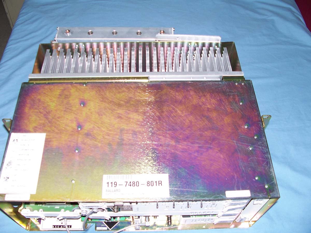
JF6-8000-2U
Oct 24, 2006Digital Transmission System Transmitter
Equipment Class
DTS - Digital Transmission System