JF6-8505U-2Digitally Modulated Radio
Alcatel USA Marketing, Inc.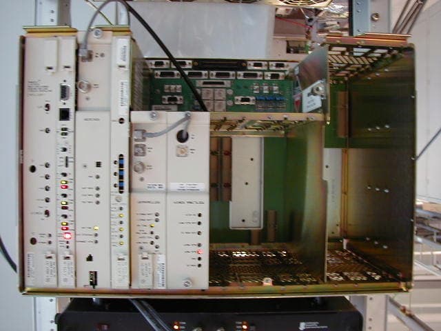
Click to zoom
Application Details
- Equipment Class
- DTS - Digital Transmission System
- Date of Grant
- Oct 02, 2002
- Application Purpose
- Original Equipment
- Date of Application
- Jul 01, 2002
- Equipment Note
- Digitally Modulated Radio
- Frequency Range
- 5725.00000000 - 5850.00000000
- Company
- Alcatel USA Marketing, Inc.
- Country
- United States
Documents & Files
Document Text
Text extracted from the exhibit documents filed with the FCC. Open a document above to read the original.
Users Manual
3DH03220MDR-8000 Series Radios Issue 6, April 2002 1-1 Page section 1 general List of Paragraphs 1.1INTRODUCTION...................................................................................... 1-3 1.2STANDARD FEATURES ............................................................................. 1-3 1.3 NAMING CONVENTION ........................................................................1-5 1.4 ORDERING INFORMATION......................................................................1-6 1.5SYSTEM CONFIGURATIONS .................................................................... 1-6 1.6RADIO CONFIGURATIONS ...................................................................... 1-6 1.6.1Basic Configurations................................................................................. 1-6 1.6.2 Ring .......................................................................................................1-7 1.6.3 Space Diversity Add-On............................................................................1-7 1.6.4Optical 2 X 4 Configuration ...................................................................... 1-7 1.7FEATURES AND OPTIONS........................................................................ 1-7 1.7.1Primary Power ......................................................................................... 1-7 1.7.2Transmit Power Level Options .................................................................... 1-7 1.7.3Differential Absolute Delay Equalization (DADE) .......................................... 1-7 1.7.4Trellis Encoding and Time Domain Equalization (TDE) ................................... 1-7 1.7.5MCS-11 Alarm/Control Interface ............................................................... 1-7 1.7.6 Foreign Alarm Interface.............................................................................1-8 1.7.7 Relay Interface Option..............................................................................1-8 1.7.8Extended Link Monitor Channel.................................................................. 1-8 1.7.9Automatic Transmitter Power Control Provisioning Option.............................. 1-8 1.7.10Service Channels Provisioning Options ....................................................... 1-8 1.7.11Mechanical Options ............................................................................... 1-10 1.7.12Capacity upgrade .................................................................................. 1-12 1.7.13Bandwidth upgrade................................................................................ 1-12 1.8USER SYSTEM INTERFACE (USI) .............................................................. 1-12 1.8.1System Security ...................................................................................... 1-12 1.9RADIO CHARACTERISTICS...................................................................... 1-13 3DH03220MDR-8000 Series Radios Issue 6, April 2002 1-2 Page 1.10EXTERNAL INTERFACE REQUIREMENTS ................................................... 1-32 1.11EQUIPMENT LISTING ............................................................................. 1-35 1.11.1Diplexer Filter Kits .................................................................................. 1-45 1.11.2Standard Filter Kits ................................................................................. 1-45 1.11.3Cable Drop Kit Option............................................................................ 1-45 1.12FAN ASSEMBLY..................................................................................... 1-45 1.13HANDSET KIT........................................................................................ 1-47 List of Tables Table 1-1Rack Options ......................................................................................... 1-11 Table 1-2Software ............................................................................................... 1-13 Table 1-3Guidelines............................................................................................. 1-13 Table 1-4Physical, Environmental, and Electrical Characteristics ................................ 1-14 Table 1-5OSS External Interface Requirements ........................................................ 1-32 Table 1-6MDR-8000/i/s Common Shelf Assembly .................................................. 1-35 Table 1-7Supplied and Optional Equipment............................................................ 1-38 Table 1-8I/O Interface Options ............................................................................. 1-40 Table 1-9XMTR Options ....................................................................................... 1-41 Table 1-10PA Options............................................................................................ 1-42 Table 1-11RCVR Options........................................................................................ 1-43 Table 1-12Capacity Keys for Transmitter and Receiver Modules .................................. 1-44 Table 1-13LBO Options.......................................................................................... 1-45 List of Figures Figure 1-1Typical MDR-8000/i/s/u Series Microwave Digital Radio ............................ 1-4 Figure 1-2Typical MDR-8000/i/s/u Component Locations and Options ...................... 1-36 Figure 1-3MDR-8000/i/s Component Locations, Rear View....................................... 1-37 Figure 1-4Fan Assembly ........................................................................................ 1-46 Table 1-14Fan Assembly/Lap Top Tray Options ........................................................ 1-46 Figure 1-5Fan Assembly With Laptop Tray Fully Extended.......................................... 1-47 Figure 1-6Handset Kit ........................................................................................... 1-48 3DH03220MDR-8000 Series Radios Issue 6, Jul…
Text truncated - open the document above for the full version.
Users Manual
3DH03220MDR-8000 Series Radios Issue 6, April 2002 6-1 Page section 6 DS3 initial turnup List of Paragraphs 6.1General .................................................................................................. 6-3 6.2Sequence of Events................................................................................... 6-3 6.3Provisioning Overview .............................................................................. 6-3 6.4Test Procedures ...................................................................................... 6-25 6.5Testing Sequence ................................................................................... 6-25 6.6Test Equipment Required ......................................................................... 6-27 List of Charts Chart 1Load MDR-8000 Software on PC..................................................................... 6-5 Chart 2Establish COM Port ........................................................................................ 6-7 Chart 3Provisioning................................................................................................. 6-11 Chart 4Transmit Crystal Oscillator Frequency Check .................................................. 6-29 Chart 5Transmitter Output Level Check (No PA) ......................................................... 6-31 Chart 6 Power Amplifier Output Level Check ............................................................. 6-35 Chart 7DS3 Radio DADE ......................................................................................... 6-39 Chart 8DS3 Line DADE............................................................................................ 6-41 Chart 9Over-The-Hop XMTR Output Power and RCVR RSL ......................................... 6-45 Chart 10Over-The-Hop DS3 BER Threshold Test........................................................... 6-47 List of Tables Table 6-1Test Equipment Required ......................................................................... 6-27 List of Figures Figure 6-1Load USI Software on PC .......................................................................... 6-6 Figure 6-2USI Computer Hookup .............................................................................. 6-8 Figure 6-3Communications Port Setup ....................................................................... 6-9 Figure 6-4Provisioning Sequence ............................................................................ 6-12 3DH03220MDR-8000 Series Radios Issue 6, April 2002 6-2 Page Figure 6-5DS3 Radio Configuration Provisioning (Sheet 1 of 3) .................................. 6-13 Figure 6-5DS3 Radio Configuration Provisioning (Sheet 2 of 3) .................................. 6-14 Figure 6-5DS3 Radio Configuration Provisioning (Sheet 3 of 3) .................................. 6-15 Figure 6-6DS3 Facilities Provisioning....................................................................... 6-16 Figure 6-7Wayside DS1 Facilities Provisioning ........................................................ 6-17 Figure 6-8DS3 Radio Service Channel Provisioning .................................................. 6-18 Figure 6-9DS3 Radio Audio Provisioning ................................................................. 6-19 Figure 6-10DS3 Radio MCS-11 Provisioning.............................................................. 6-20 Figure 6-11ELMC Provisioning ................................................................................. 6-21 Figure 6-12ELMC Remote Time-Out Constant Provisioning ........................................... 6-22 Figure 6-13Control Names Provisioning .................................................................... 6-23 Figure 6-14DS3 Station Alarm Names Provisioning .................................................... 6-24 Figure 6-15Testing Sequence ................................................................................... 6-26 Figure 6-16Transmit Crystal Oscillator Frequency Check.............................................. 6-30 Figure 6-17Transmitter Output Level Check (No PA) .................................................... 6-33 Figure 6-18PA Output Level Check............................................................................ 6-38 Figure 6-19DS3 Radio DADE Adjustment................................................................... 6-40 Figure 6-20DS3 Line DADE Adjustment ..................................................................... 6-42 Figure 6-21DADE Fine Tuning .................................................................................. 6-43 Figure 6-22XMT Output Power and RSL Test............................................................... 6-46 Figure 6-23DS3 BER Threshold Test (Sheet 1 of 2) ...................................................... 6-51 Figure 6-23DS3 BER Threshold Test (Sheet 2 of 2) ...................................................... 6-53 3DH03220MDR-8000 Series Radios Issue 6, July 2002DS3 Initial Turnup 6-3 6 DS3 INITIAL TURNUP 6.1 GENERAL This section describes the procedures required to turn up the DS3 MDR-8000/i Microwave Digital Radios after installation. 6.2 SEQUENCE OF EVENTS Perform the following initial turnup procedures in sequence: 1 Install software on PC (Chart 1). Software installed at the factory before delivery should not be overwritten by downloading to the radio controller at initial tur- nup. Refer to Section 10, Maintenance for procedure to upgrade existing software. 2 Establish communication between radio and USI computer (Chart 2). 3 Provision radio (Chart 3). Before troubleshooting a radio that is not performing correctly, check that the antenna has been aligned by contacting the program manager, project engineer, or appropriate customer representative. 4 Perform applicable test procedures (Chart 4 through Chart 10). 5 Log test results on field test data sheet. 6.3 PROVISIONING OVERVIEW This part of the section describes provisioning options avail…
Text truncated - open the document above for the full version.
Attestation Statements
Alcatel 1000 Coit Rd., Plano, Texas, 75075 August 09, 2002 ALCATEL USA WIRELESS TRANSMISSION DEVISION 1000 Coit Rd. Pano, Tx 75075 To Whom It May Concern: MDR-8X05u- XX RADIOS MUST BE PRO FESSIONALLY INSTALLED AND THERFORE THEY ARE EXEMPT FROM THE ANTENNA RESTRICTIONS (FCC PART 15.203), INCLUDING INFORMATION ON ANTENNAS USED FOR TESTING The above statement is in regard with the professional installation of the MDR-8X05u-XX radios (MDR-8505u-2, MDR-8505u-4, MDR-8505u-8, MDR-8505u-16, MDR-8605u-45) and the antennas used for testing. The MDR-8X05u-XX radios must be professionally installed and for that reason they are exempt from the antenna restrictions of the FCC Part 15.203. ALCATEL developed and manufactured this radio. These radios are part of the larger MDR- 8000/i/s/u series Microwave Digital Radio that provides transport for DS1, E1, DS3, and OC3 in 2, 6, 7, 8, 10, and 11Ghz licensed frequency bands. The MDR-8X05u-XX family of radios uses digitally modulated signals and it is to be certified for operation under Part 15.247 of the FCC Rules (including the new rules adopted under Docket No. 99- 123). The radio is designed for point-to-point communications in the 5.725-5.850Ghz band and will provide transport for 2DS1, 4DS1, 8DS1, 16DS1 capacities using 32 TCM modulation scheme and 1DS3 capacity with 64QAM modulation scheme. Due to the unique requirements of installation and turn-on procedures, typical consumers or businesses will not have the proper training required for successful implementation of these radios. The MDR-8X05u-XX radios are not designed for use by general public, and will be sold through ALCATEL sales department only, or 3 rd party distributors, to professional communications users in the following category: regional Bell operating companies, telecommunication companies, personal communication service companies, power electric utilities, etc These companies will either use their professional telecommunications engineering staff to carry out the installation or will subcontract to professional installation firms. The MDR-8X05u-XX radios will be used for point –to-point communications only, as fixed, permanent or temporary links requiring the use of directional antennas mounted outdoor, usually on a tower. These antennas have narrow beamwidths and require a professional installer for alignment. Alcatel 1000 Coit Rd., Plano, Texas, 75075 The maximum transmit power of the MDR-8X05u-XX radio is 1Watt(30dbm) and it is adjusted in the factory during the final tests. However the output power can be adjusted to lower levels by professional installer during installation. The method of adjusting the output power is described in the manual written for use by professional trained installers. This radio is sold without antenna and the customer chooses from commercially available antennas. Theodore Timaru Electrical Design Engineer RF Design Wireless Transmission Division
Attestation Statements
Alcatel 1000 Coit Rd., Plano, Texas, 75075 August 27, 2002 ALCATEL USA WIRELESS TRANSMISSION DEVISION 1000 Coit Rd. Pano, Tx 75075 To Whom It May Concern: This letter is to comply with Section 0.457(d)(2)(I) pertaining to confidential material. Alcatel would like all the documents uploaded with the request for confidentiality to be kept confidential. These documents are: 1. MDR-8X05u-X (MDR-8X05u-2, -8X05u-4, -8X08u-8, -8X05u-16, -8605u-45 ) schematics 2. MDR-8X05u-X photos of modules without covers (shielding) The contents of these documents are proprietary to Alcatel and therefore should not be accessible to the general public. Theodore Timaru Electrical Design Engineer RF Design Wireless Transmission Division
Block Diagram
- 1 - FCC Part 15.247 Digital Modulation Technique Certification Alcatel 1000 Coit Rd., Plano, Texas, 75075 APPLICATION FOR FCC CERTIFICATION ALCATEL USA Digitally Modulated Radio MODEL FCC ID MDR-8505u-2 JF6-8505u-2 MDR-8505u-4 JF6-8505u-4 MDR-8505u-8 JF6-8505u-8 MDR-8505u-16 JF6-8505u-16 MDR-8605u-45 JF6-8605u-45 Number of Pages: 61 Date of Report: June 26, 2002 - 2 - FCC Part 15.247 Digital Modulation Technique Certification Alcatel 1000 Coit Rd., Plano, Texas, 75075 Table of Contents 1.0 Summary of tests -----------------------------------------------------------3 2.0 General Description --------------------------------------------------------4 2.1 Standard Features--------------------------------------------------4 2.2 Naming Convention -----------------------------------------------7 2.3 System Configuration---------------------------------------------8 2.4 Radio Configuration-----------------------------------------------8 2.5 Functional description------------------------------------------12 3.0 Test Methodology----------------------------------------------------------14 3.1 Test Facility-------------------------------------------------------- 14 3.1 List of Test Equipment------------------------------------------16 4.0 Measurements Results---------------------------------------------------18 4.1 Maximum Conducted Output Power-----------------------18 4.2 Minimum 6DB RF Bandwidth---------------------------------19 4.3 Peak Power Spectral Density-------------------------------- 21 4.4 Out of Band Conducted Emissions------------------------ 27 4.4.1 MDR-8505u-2--------------------------------------------28 4.4.2 MDR-8505u-4--------------------------------------------34 4.4.3 MDR-8505u-8--------------------------------------------40 4.4.4 MDR-8505u-16------------------------------------------ 46 4.4.4 MDR-8605u-45------------------------------------------ 52 4.5 Out of Band Radiated Emissions-----------------------------58 4.6 Radiated Emissions in Restricted Bands------------------58 4.7 Antenna Requirement--------------------------------------------61 - 3 - FCC Part 15.247 Digital Modulation Technique Certification Alcatel 1000 Coit Rd., Plano, Texas, 75075 1.0 Summary of FCC 15.247 Tests Model: MDR-8505u-2 FCC ID: JF6-8505u-2 MDR-8505u-4 JF6-8505u-4 MDR-8505u-8 JF6-8505u-8 MDR-8505u-16 JF6-8505u-16 MDR-8605u-45 JF6-8605u-45 TestFCC Reference Results Max. Output Power15.247 (b) (3) Pass 6db Bandwidth15.247 (a) (2) Pass Peak Power Spectral Density 15.247 (d) Pass Out of Band Conducted Emissions 15.247 (c) Pass AC Conducted Emissions 15.207Not required; battery operation only Out of Band Radiated Emissions 15.247 (c) N/A Antenna requirement 15.203 Pass Elec. Design Engineer: Theodore Timaru Date: 06/26/02 RF Group Manager: Duane Mortensen Date: 06/26/02 - 4 - FCC Part 15.247 Digital Modulation Technique Certification Alcatel 1000 Coit Rd., Plano, Texas, 75075 2.0 General Description The MDR-8X05-XX is the MDR-8000/i/s/u version for the unlicensed frequency band: 5725- 5850Mhz. It is the latest addition of the Alcatel family of digital microwave products. The MDR–8000/i/s/u series Microwave Digital Radios (see figure 2–1) consists of: ·Solid–state, licensed, digital radios that provide transport for DS1, E1, and DS3 in 2, 6, 7, 8, 10, and 11 GHz RF frequency bands and OC3 in 6, 7, 8, 10, and 11 GHz RF frequency bands ·Solid–state, unlicensed digital radios that provide transport for DS1 and DS3 in the 5 GHz RF frequency band. The following capacities and modulation schemes are available: · MDR–8000 – 2, 4, 8, 12, or 16 North American Standard DS1 channels at either 32 or 128 TCM or 1 or 3 North American Standard DS3 channels with 1 or 3 wayside DS1 channels at 64 QAM · MDR–8000i – 2, 4, 8, 12, or 16 CCITT E1 channels at either 32 or 128 TCM ·MDR–8000s – 3 North American Standard STS1 channels with 3 wayside DS1 channels at 128 TCM · MDR–8000u– 2, 4, 8, or 16 North American Standard DS1 channels at 32 TCM or 1 North American Standard DS3 channel with 1 wayside DS1 channel at 16 or 64 QAM. The radio fits into a standard 19 in. (483 mm) rack and occupies seven vertical rack increments. Up to four fully–equipped hot–standby radios can be mounted in a standard 7 ft rack. The radio is front accessible and can be mounted against a wall or back–to–back against other equipment. 2.1 STANDARD FEATURES Standard features include: ·Frequency bands from 2 to 11 GHz - 5 - FCC Part 15.247 Digital Modulation Technique Certification Alcatel 1000 Coit Rd., Plano, Texas, 75075 ·Committee of European Post and Telegraph (CEPT)/Federal Communications Commission (FCC) applications ·DS1, E1, DS3, and OC3 Traffic capacities. ·International Telecommunications Union (ITU)/ETSI/FCC compliant ·Five configuration options ·Upstream management compatibility ·User–friendly Personal Computer (PC) monitor and control ·Automatic Transmitter Power Control (ATPC) ·Adaptive Time Domain Equalization (TDE) ·Extended Link Monitor Channel (ELMC) ·MCS–11/Telemetry Byte Oriented Serial (TBOS) Alarm/Control Interface ·Two independent PCM audio channels - 6 - FCC Part 15.247 Digital Modulation Technique Certification Alcatel 1000 Coit Rd., Plano, Texas, 75075 Figure 2–1 Typical MDR–8000/i/s/u Series Microwave Digital Radio - 7 - FCC Part 15.247 Digital Modulation Technique Certification Alcatel 1000 Coit Rd., Plano, Texas, 75075 2.2 NAMING CONVENTION The MDR–8000/i/s/u series radio naming conventions are as follows: - 8 - FCC Part 15.247 Digital Modulation Technique Certification Alcatel 1000 Coit Rd., Plano, Texas, 75075 2.3 SYSTEM CONFIGURATIONS The MDR–8000/i/s radio can be provisioned as a terminal, synchronous repeater, ring terminal, or ring repeater. 2.4 RADIO CONFIGURATIONS 2.4.1 Basic Configurations The MDR–8000/i/s/u supports the three basic configurations: ·Non–standby – available in all frequency bands – stand alone transmitter/receiver combination ·Hot–standby – available in all frequency bands – pair of transmitters a…
Text truncated - open the document above for the full version.
Cover Letter(s)
Alcatel 1000 Coit Rd., Plano, Texas, 75075 September 26, 2002 ALCATEL USA WIRELESS TRANSMISSION DEVISION 1000 Coit Rd. Pano, Tx 75075 To Whom It May Concern: This letter is to comply with Section 0.457(d)(2)(I) pertaining to confidential material. Alcatel would like all the documents uploaded with the request for confidentiality to be kept confidential. These documents are: 1. MDR-8X05u-X (MDR-8X05u-8, -8605u-45 ) schematics The contents of these documents are proprietary to Alcatel and therefore should not be accessible to the general public. Theodore Timaru Electrical Design Engineer RF Design Wireless Transmission Division
External Photos
- 1 - FCC Part 15.247 Digital Modulation Technique Certification Alcatel 1000 Coit Rd., Plano, Texas, 75075 APPLICATION FOR FCC CERTIFICATION ALCATEL USA Digitally Modulated Radio MODEL FCC ID MDR-8505u-2 JF6-8505u-2 MDR-8505u-4 JF6-8505u-4 MDR-8505u-8 JF6-8505u-8 MDR-8505u-16 JF6-8505u-16 MDR-8605u-45 JF6-8605u-45 Number of Pages: 61 Date of Report: June 26, 2002 - 2 - FCC Part 15.247 Digital Modulation Technique Certification Alcatel 1000 Coit Rd., Plano, Texas, 75075 Table of Contents 1.0 Summary of tests -----------------------------------------------------------3 2.0 General Description --------------------------------------------------------4 2.1 Standard Features--------------------------------------------------4 2.2 Naming Convention -----------------------------------------------7 2.3 System Configuration---------------------------------------------8 2.4 Radio Configuration-----------------------------------------------8 2.5 Functional description------------------------------------------12 3.0 Test Methodology----------------------------------------------------------14 3.1 Test Facility-------------------------------------------------------- 14 3.1 List of Test Equipment------------------------------------------16 4.0 Measurements Results---------------------------------------------------18 4.1 Maximum Conducted Output Power-----------------------18 4.2 Minimum 6DB RF Bandwidth---------------------------------19 4.3 Peak Power Spectral Density-------------------------------- 21 4.4 Out of Band Conducted Emissions------------------------ 27 4.4.1 MDR-8505u-2--------------------------------------------28 4.4.2 MDR-8505u-4--------------------------------------------34 4.4.3 MDR-8505u-8--------------------------------------------40 4.4.4 MDR-8505u-16------------------------------------------ 46 4.4.4 MDR-8605u-45------------------------------------------ 52 4.5 Out of Band Radiated Emissions-----------------------------58 4.6 Radiated Emissions in Restricted Bands------------------58 4.7 Antenna Requirement--------------------------------------------61 - 3 - FCC Part 15.247 Digital Modulation Technique Certification Alcatel 1000 Coit Rd., Plano, Texas, 75075 1.0 Summary of FCC 15.247 Tests Model: MDR-8505u-2 FCC ID: JF6-8505u-2 MDR-8505u-4 JF6-8505u-4 MDR-8505u-8 JF6-8505u-8 MDR-8505u-16 JF6-8505u-16 MDR-8605u-45 JF6-8605u-45 TestFCC Reference Results Max. Output Power15.247 (b) (3) Pass 6db Bandwidth15.247 (a) (2) Pass Peak Power Spectral Density 15.247 (d) Pass Out of Band Conducted Emissions 15.247 (c) Pass AC Conducted Emissions 15.207Not required; battery operation only Out of Band Radiated Emissions 15.247 (c) N/A Antenna requirement 15.203 Pass Elec. Design Engineer: Theodore Timaru Date: 06/26/02 RF Group Manager: Duane Mortensen Date: 06/26/02 - 4 - FCC Part 15.247 Digital Modulation Technique Certification Alcatel 1000 Coit Rd., Plano, Texas, 75075 2.0 General Description The MDR-8X05-XX is the MDR-8000/i/s/u version for the unlicensed frequency band: 5725- 5850Mhz. It is the latest addition of the Alcatel family of digital microwave products. The MDR–8000/i/s/u series Microwave Digital Radios (see figure 2–1) consists of: ·Solid–state, licensed, digital radios that provide transport for DS1, E1, and DS3 in 2, 6, 7, 8, 10, and 11 GHz RF frequency bands and OC3 in 6, 7, 8, 10, and 11 GHz RF frequency bands ·Solid–state, unlicensed digital radios that provide transport for DS1 and DS3 in the 5 GHz RF frequency band. The following capacities and modulation schemes are available: · MDR–8000 – 2, 4, 8, 12, or 16 North American Standard DS1 channels at either 32 or 128 TCM or 1 or 3 North American Standard DS3 channels with 1 or 3 wayside DS1 channels at 64 QAM · MDR–8000i – 2, 4, 8, 12, or 16 CCITT E1 channels at either 32 or 128 TCM ·MDR–8000s – 3 North American Standard STS1 channels with 3 wayside DS1 channels at 128 TCM · MDR–8000u– 2, 4, 8, or 16 North American Standard DS1 channels at 32 TCM or 1 North American Standard DS3 channel with 1 wayside DS1 channel at 16 or 64 QAM. The radio fits into a standard 19 in. (483 mm) rack and occupies seven vertical rack increments. Up to four fully–equipped hot–standby radios can be mounted in a standard 7 ft rack. The radio is front accessible and can be mounted against a wall or back–to–back against other equipment. 2.1 STANDARD FEATURES Standard features include: ·Frequency bands from 2 to 11 GHz - 5 - FCC Part 15.247 Digital Modulation Technique Certification Alcatel 1000 Coit Rd., Plano, Texas, 75075 ·Committee of European Post and Telegraph (CEPT)/Federal Communications Commission (FCC) applications ·DS1, E1, DS3, and OC3 Traffic capacities. ·International Telecommunications Union (ITU)/ETSI/FCC compliant ·Five configuration options ·Upstream management compatibility ·User–friendly Personal Computer (PC) monitor and control ·Automatic Transmitter Power Control (ATPC) ·Adaptive Time Domain Equalization (TDE) ·Extended Link Monitor Channel (ELMC) ·MCS–11/Telemetry Byte Oriented Serial (TBOS) Alarm/Control Interface ·Two independent PCM audio channels - 6 - FCC Part 15.247 Digital Modulation Technique Certification Alcatel 1000 Coit Rd., Plano, Texas, 75075 Figure 2–1 Typical MDR–8000/i/s/u Series Microwave Digital Radio - 7 - FCC Part 15.247 Digital Modulation Technique Certification Alcatel 1000 Coit Rd., Plano, Texas, 75075 2.2 NAMING CONVENTION The MDR–8000/i/s/u series radio naming conventions are as follows: - 8 - FCC Part 15.247 Digital Modulation Technique Certification Alcatel 1000 Coit Rd., Plano, Texas, 75075 2.3 SYSTEM CONFIGURATIONS The MDR–8000/i/s radio can be provisioned as a terminal, synchronous repeater, ring terminal, or ring repeater. 2.4 RADIO CONFIGURATIONS 2.4.1 Basic Configurations The MDR–8000/i/s/u supports the three basic configurations: ·Non–standby – available in all frequency bands – stand alone transmitter/receiver combination ·Hot–standby – available in all frequency bands – pair of transmitters a…
Text truncated - open the document above for the full version.
External Photos
- 1 - FCC Part 15.247 Digital Modulation Technique Certification Alcatel 1000 Coit Rd., Plano, Texas, 75075 Appendix C: External Photos MDR-8X05u-XX radio mounted in a rack with cover on. - 2 - FCC Part 15.247 Digital Modulation Technique Certification Alcatel 1000 Coit Rd., Plano, Texas, 75075 MDR-8X05u-XX radio (non-standby) without cover.
ID Label/Location Info
APPENDIX A: FCC ID Location
Internal Photos
- 1 - FCC Part 15.247 Digital Modulation Technique Certification Alcatel 1000 Coit Rd., Plano, Texas, 75075 Appendix B: Assembly and Card Photographs Power Amplifier (cover view) - 2 - FCC Part 15.247 Digital Modulation Technique Certification Alcatel 1000 Coit Rd., Plano, Texas, 75075 Power Amplifier (back view) - 3 - FCC Part 15.247 Digital Modulation Technique Certification Alcatel 1000 Coit Rd., Plano, Texas, 75075 Transmitter (cover view) - 4 - FCC Part 15.247 Digital Modulation Technique Certification Alcatel 1000 Coit Rd., Plano, Texas, 75075 Transmitter (back view) - 5 - FCC Part 15.247 Digital Modulation Technique Certification Alcatel 1000 Coit Rd., Plano, Texas, 75075 Receiver (cover view) - 6 - FCC Part 15.247 Digital Modulation Technique Certification Alcatel 1000 Coit Rd., Plano, Texas, 75075 Receiver (back view) - 7 - FCC Part 15.247 Digital Modulation Technique Certification Alcatel 1000 Coit Rd., Plano, Texas, 75075 I/O Interface Card (cover view) - 8 - FCC Part 15.247 Digital Modulation Technique Certification Alcatel 1000 Coit Rd., Plano, Texas, 75075 I/O Interface Card (back view) - 9 - FCC Part 15.247 Digital Modulation Technique Certification Alcatel 1000 Coit Rd., Plano, Texas, 75075 Controller Card (component view) - 10 - FCC Part 15.247 Digital Modulation Technique Certification Alcatel 1000 Coit Rd.,…
Text truncated - open the document above for the full version.
Contact Information
Applicant
Alfred Holland(R&D Manager)
Technical Contact
Test Firm
Alcatel USA, Inc.Steve Bloom
972-519-5228Fax: 972-519-2618
Technical Specifications
| # | Rule Parts | Frequency Range | Power Output |
|---|---|---|---|
| 1 | - | 5.72 GHz - 5.85 GHz | 1 W |
Other Applications from Alcatel USA Marketing, Inc.
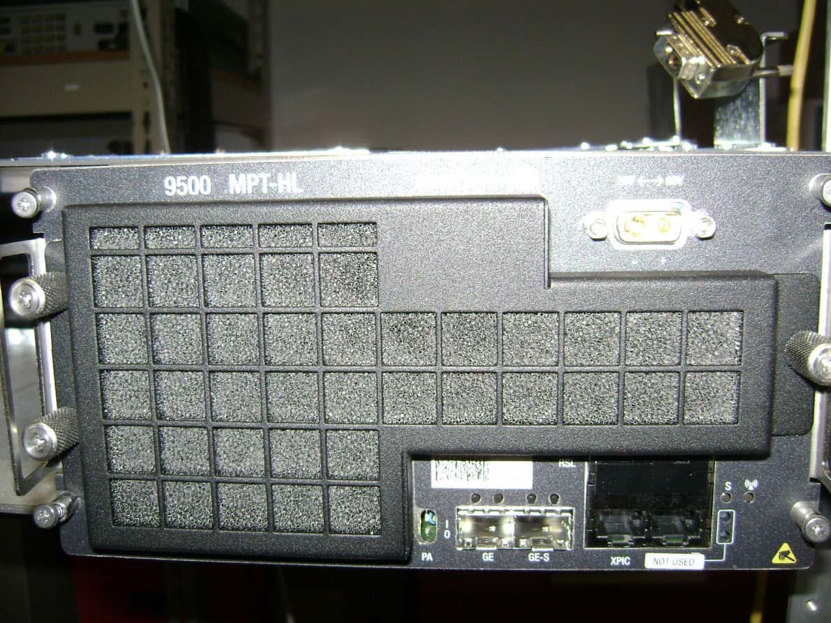
JF6-9558L-D
May 28, 20155 GHz rack-mounted point to point transceiver
Equipment Class
DTS - Digital Transmission System
JF6-9558L
May 28, 20155 GHz rack-mounted point to point transceiver
Equipment Class
DTS - Digital Transmission System
JF6-9558HC
Aug 06, 2012Microwave Packet Radio
Equipment Class
DTS - Digital Transmission System
JF6-8702-50
Apr 26, 2010MDR-8000
Equipment Class
TNB - Licensed Non-Broadcast Station Transmitter
JF6-9558H
Jan 03, 2010MPT-HL Packet Terminal
Equipment Class
DTS - Digital Transmission System