JF6-8702-8MDR-8702-8
Alcatel USA Marketing, Inc.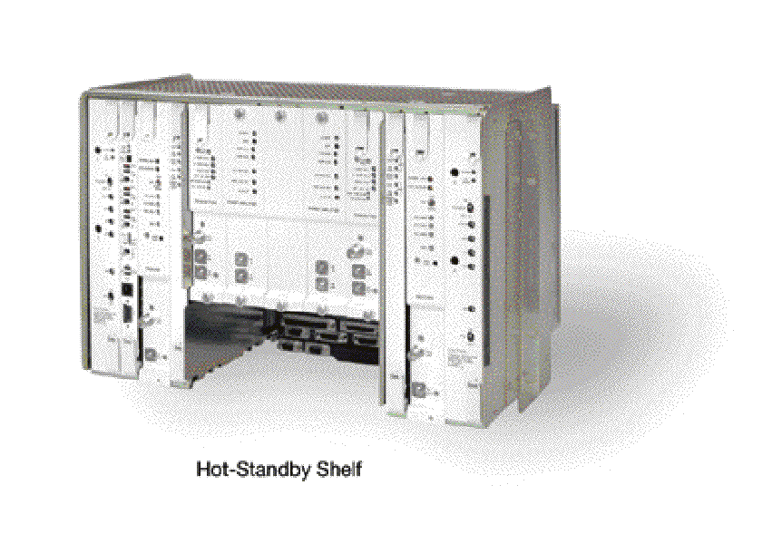
Click to zoom
Application Details
- Equipment Class
- PCB - PCS Licensed Transmitter
- Date of Grant
- Dec 20, 2004
- Application Purpose
- Original Equipment
- Date of Application
- Jun 22, 2004
- Equipment Note
- MDR-8702-8
- Frequency Range
- 1850.00000000 - 1990.00000000
- Company
- Alcatel USA Marketing, Inc.
- Country
- United States
Documents & Files
Document Text
Text extracted from the exhibit documents filed with the FCC. Open a document above to read the original.
Users Manual
EXHIBIT 6. USER’S MANUAL The MDR-8000 series Microwave Digital Radios (see Figure ) consists of: • Solid-state, licensed, digital radios that provide transport for DS1 and E1 in 1.85, 2, 6, 7, 8, 10, and 11 GHz RF bands, DS3 in 2, 6, 7, 8, and 11 GHz RF bands, and OC3 in 6, 7, 8, and 11 GHz RF bands • Solid-state, unlicensed digital radios that provide transport for DS1 and DS3 in the 5 GHz RF frequency band. The following capacities and modulation schemes are available: • MDR-8000 – 2, 4, 8, 12, or 16 North American Standard DS1 channels at either 32 or 128 TCM or 1, 2, or 3 North American Standard DS3 channels with 1, 2, or 3 wayside DS1 channels at 64 QAM • MDR-8000i – 2, 4, 8, 12, or 16 CCITT E1 channels at either 32 or 128 TCM • MDR-8000s – OC3 (3 North American Standard STS1 channels with 3 wayside DS1 channels) or 1 STS1 channel with one wayside DS1 at 128 TCM • MDR-8000u – 2, 4, 8, or 16 North American Standard DS1 channels at 32 TCM or 1 North American Standard DS3 channel with 1 wayside DS1 channel at 64 QAM. SHELF CONFIGURATIONS The MDR-8000 is available in two shelf configurations: hot-standby and CommPak. HOT STANDBY SHELF The MDR-8000 hot-standby shelf is wired hot-standby and can be configured non- standby, where only the A-side is populated, or hot-standby, where both the A- and the B- sides are populated. The hot-standby shelf fits into a standard 19 in. (483 mm) rack and occupies seven vertical rack increments. Up to four fully equipped hot-standby radios can be mounted in a standard 7 ft. rack. The radio is front accessible and can be mounted against a wall or back-to-back against other equipment. COMMPAK RADIO The MDR-8000 CommPak radio is available as a full indoor shelf or outdoor unit in a cabinet. COMMPAK INDOOR SHELF The CommPak indoor shelf is wired and configured non-standby only. The indoor shelf fits into a standard 19 in. (483 mm) rack and occupies four vertical rack increments (7 in.). The radio is front accessible and can be mounted against a wall or back-to-back against other equipment. COMMPAK OUTDOOR UNIT The MDR-8000 outdoor unit consists of the CommPak indoor shelf mounted vertically in a 20 in. high x 7.5 in. wide x 12.5 in. deep enclosure. STANDARD FEATURES Standard features include: • Frequency bands from 1.85 to 11 GHz • Committee of European Post and Telegraph (CEPT)/Federal Communications Commission (FCC) applications • DS1, E1, DS3, and OC3 Traffic capacities • International Telecommunications Union (ITU)/ETSI/FCC compliant • Five configuration options • Upstream management compatibility. • User-friendly Personal Computer (PC) monitor and control • Automatic Transmitter Power Control (ATPC) • Adaptive Time Domain Equalization (TDE) • Extended Link Monitor Channel (ELMC) • MCS-11/Telemetry Byte Oriented Serial (TBOS) Alarm/Control Interface • Two independent PCM audio channels Figure 1 Typical MDR-8000 Series Microwave Digital Radio Table Physical, Environmental, and Electrical Characteristics ITEM CHARACTERISTICS PHYSICAL CHARACTERISTICS Dimensions WIDTH DEPTH HEIGHT Hot-Standby Shelf 483 mm (19 in.) 406.4 mm (16.25 in.) 311.15 mm (12.25 in.) CommPak Indoor Shelf 483 mm (19 in.) 406.4 mm (16.25 in.) 177.8 mm (7.0 in.) Weight (Hot-Standby Terminal)38.6 kg (85 lbs) ENVIRONMENTAL CHARACTERISTICS Ambient Temperature Spec Compliant Operating Without Failure Nonoperating 32° to 122°F (0° to 50°C) - 4° to 158°F (- 20° to 70°C) - 40° to 176°F (- 40° to 80°C) Altitude Operating Nonoperating Relative Humidity Vibration and Shock Duty Cycle -350 to 16500 ft (-100 to 5000 m) -350 to 40000 ft (-100 to 12000 m) 5 to 95 percent (without condensation) Normal Storage and Handling Continuous, unattended COMMON ELECTRICAL CHARACTERISTICS Primary Input Voltage ±20.5 to ±60.0 Vdc RF CHANNEL FREQUENCY (MHZ) MDR-8X02/i-X MDR-8X05u-X MDR-8X06/i/s-X MDR-8X07/i/s-X MDR-8X08/i/s-X MDR-8X10/i/s-X MDR-8X11/i/s-X 1850-2285 5725-5850 5850-7125 7125-7750 7700-8500 10440-10680 10700-11700 XMT OUTPUT POWER (DBM, NOMINAL) XMTR (NO PA) OPTIONAL PA INSTALLED MDR-8X02/i-X MDR-8505u-X MDR-8605u-X MDR-8X06/i/s-X MDR-8X07/i/s-X +14 +15 +14 +14 +14 +30 or +33 +25 or +30 +23 or +29 +23 or +29 or +31 or +33 MDR-8X08/i/s-X MDR-8X10/i/s-X MDR-8X11/i/s-X +14 +15 +15 +28 or +30 +28 or +30 or +32 +23 or +27 or +29 +23 or +27 or +29 Note: XMT Power Referenced at the SMA output of the diplexer filter or the top of the stack for waveguide stacking configurations. Figure 1. Typical MDR-8000 Hot-Standby Shelf Component
External Photos
Exhibit 2 Figure 1 Typical MDR-8000 Series Microwave Digital Radio Figure 1 Typical MDR-8000 Hot-Standby Shelf Component
Internal Photos
Exibit #7 Internal photos Power Amplifier ( P.A.) Transmitter
Internal Photos
EXHIBIT 7. INTERNAL PHOTOS I/O CONDITIONER CIRCUIT SIDE I/O CONDITI0NER SOLDER SIDE TRANSMITTER RF CIRCUIT SIDE TRANSMITTER RF SOLDER SIDE TRANSMITTER BASEBAND CIRCUIT SIDE TRANSMITTER BASEBAND SOLDER SIDE PA RF CIRCUIT SIDE PA RF SOLDER SIDE PA BIAS BOARD CIRCUIT SIDE PA BIAS BOARD SOLDER SIDE
Operational Description
EXHIBIT 9. MDR–8000 Operational Description In the transmit direction the MDR–8000 uses a modulation structure where the I and Q baseband signals modulate the in–phase and quadrature phase components of the transmitter. The DS1/E1 I/O interface converts the format of the incoming DS1/E1 data streams to I, Q, data, and clock. The DS1/E1 I/O interface module uses the DS1/E1 signals to generate 32 or 128 trellis code amplitude modulated (TCM) baseband signals The transmitter processes the TCM baseband signals to generate the modulated TCM RF signal. The RF signal is then amplified and applied directly to the antenna branching or further amplified by a solid–state amplifier (optional) and applied to the antenna branching. The DS3 I/O interface converts the format of the incoming DS3 and Wayside (WS) DS1 data streams to I, Q, data, and clock. The I/O interface module uses the DS3 signals to generate 64 Quadrature Amplitude Modulated (QAM) baseband signals. The transmitter processes the QAM baseband signals to generate the modulated QAM RF signal. The RF signal is then amplified and applied directly to the antenna branching or further amplified by a solid–state amplifier (optional) and applied to the antenna branching. In the receive direction, the MDR–8000 uses a demodulation conversion structure. The received TCM or QAM RF signal is fed into a filter followed by a receiver module. The receiver module directly converts the RF signal to I and Q baseband signals and provides all of the acquisition loops. The receiver also provides countermeasures to dynamic path distortions. Clock and digital data are extracted from the analog channels and passed on to the I/O interface. The digital data is processed by the I/O interface module and converted to a DS1/E1 or DS3 format. In-Band PCS development requirements: Four components need to be developed: Transmitter Receiver Power Amplifier RF filters. The Transmitter, Receiver and Power Amplifier are all modified versions of the Canadian band modules. The filters are application dependent. Diplexing filters will be used when both the up and down link can be used and T/R separation is above 65 MHz. Band pass filters with a band reject cell will be used for co-locating situations. Transmitter: • The main development of the Transmitter is to improve the out-of-band noise floor. • One goal is to increase the frequency flexibility of the current 2GHz Transmitter to accommodate the PCS, Canadian Band and unlicensed applications. • The transmitter design is based on a phase locked VCO which is a stepping stone to a synthesized transmitter in the future. • The requirements are as follows: • T/L PN: 3EM11962AAAA • PB/RF: 3EM11960ABAA • PBA/RF: 3EM11961AAAB • BB ASSY: 3DH03139 (same as 8 GHz) • Frequency range: 1850 – 1990 MHz (PCS Band) 2025 – 2285 MHz (Canadian Band) 2400 – 2483 MHz (Unlicensed Band) There will most likely be 3 realization variants of the RF PBA and T/L assemblies. • RF DC requirements: +/- 5 VDC, +10.5 VDC, +/- 12 VDC • Interface requirement: • Baseband interface: 20 pin, thru hole male connector • I/Q inputs:------- -10dBm • RF detect:------ 500mV +/- 50mV • DC:-------------- +10.5 +/- .2 VDC +5 +/- .1 VDC -5 +/- .1 VDC +12 +/- .2 VDC -12 +/- .2 VDC • Freq Ctrl---------- +3.0 VDC • VVA control------ 0 to 3 VDC • LO interface: 10 pin ribbon connector • LO level: --------- +10 dBm +/- 2 dB • LO monitor: BNC connector • LO level: --------- -10 dBm +/- 2 dB • RF monitor: SMA connector • Level: -------------- 0 dBm +/- 2 dB • RF monitor: SMA connector • Level: ------------- +18 dBm Receivers: • The Receiver effort will be an effort to maximize T/I performance, modifying some baseband filtering and optimizing gain/linearity of the design. The design is based on a phase locked VCO. As with the transmitter, receiver frequency flexibility is required. • The requirements are as follows: • T/L PN: 3EM11964AAAA • PB/RF: 3EM11963ABAA • PBA/RF: 3EM11963AAAB • BB ASSY: 3EM11554AA • Frequency range: 1850 – 1990 MHz (PCS Band) 2025 – 2285 MHz (Canadian Band) 2400 – 2483 MHz (Unlicensed Band) There will most likely be 3 realization variants of the RF PBA and T/L assemblies. • RF DC requirements: +/- 5 VDC, +/- 12 VDC • Interface requirement: • Baseband interface: 20 pin, thru hole male connector • DC:--------------- +5 +/- .1 VDC -5 +/- .1 VDC +12 +/- .2 VDC -12 +/- .2 VDC • Freq Ctrl---------- +3.0 VDC • AFC -------------- 0 to 3 VDC • LO interface: 10 pin ribbon connector • LO level: --------- +10 dBm +/- 2 dB • LO monitor: BNC connector • LO level: --------- -10 dBm +/- 2 dB • RF input: SMA connector • Input Level: ---- -15 to -92 dBm • RF Gain: ----------28 dB max. • NF: -------------- 2.8 dB max. Power Amplifiers: • The Power amplifier will be a slight modification of the Canadian 2GHz. • RF input: SMA connector • Input Level: ---------- -12 dBm • RF Gain: ---------------20 dB max. • RF Output: SMA connector • RF Output Pwr: ------+33 dBm max.
Parts List/Tune Up Info
6-3 6 INITIAL TURNUP 6.1 SECTION INTRODUCTION This section describes the procedures required to turn up the MDR-8000 Microwave Digital Radios after installation. This provisioning part of the section describes provisioning options available with the MDR-8000 software application. Provisioning allows for the definition, editing, and storing of specific functions. The MDR-8000 provides the ability to provision equipment and facili- ties through a series of Windows™-based screens and messages. The Provisioning menu lists equipment and functions which may be provisioned. You should use only those provi- sioning screens that are applicable to your radio. Refer to the Users Guide section and applicable DS1/E1, DS3, or OC3 Initial Turnup section on the attached CD for more infor- mation. 6.2 RECOMMENDED SEQUENCE Perform the following initial turnup procedures in sequence: 1 Install software on PC. Software installed at the factory before delivery should not be overwrit- ten by downloading to the radio controller at initial turnup. Refer to Maintenance section on the attached CD for procedure to upgrade existing software. 2 Establish communication between radio and USI computer. Saving provisioning on disk provides a reference for any future provi- sioning changes. 3 Provision radio. See Figure 6-1. The radio has been properly aligned and tested at the factory before shipment eliminating the need for testing after initial turn-up. The only time testing and/or adjustment is required is after a maintenance action such as removal and replacement procedure and/or constant alarms requiring corrective maintenance action. The completed maintenance action procedure(s) will reference any required test procedure(s). Note Note 6-4 Figure 6-1 Provisioning Sequence LMW-9038-sm 01/23/04 FIG 6-5 DS3 RADIO CONFIG PROVISIONING FIG 6-2 DS1/E1, DS3, OC3 RADIO CONFIG PROVISIONING FIG 6-6 DS3 FACILITIES PROVISIONING FIG 6-3 DS1/E1 RADIO CONFIG PROVISIONING FIG 6-4 DS1/E1 FACILITIES PROVISIONING FIG 6-7 OC3 RADIO CONFIG PROVISIONING FIG 6-8 OC3 FACILITIES PROVISIONING FIG 6-9 DS3, OC3 RADIO WAYSIDE DS1 FACILITIES PROVISIONING FIG 6-13 DS1/E1, DS3, OC3 RADIO ELMC PROVISIONING FIG 6-10 DS1/E1, DS3, OC3 RADIO SERVICE CHANNEL PROVISIONING FIG 6-11 DS1/E1, DS3, OC3 RADIO AUDIO PROVISIONING FIG 6-12 DS1/E1, DS3, OC3 RADIO MCS-11 PROVISIONING FIG 6-14 DS1/E1, DS3, OC3 RADIO ELMC REMOTE TIME-OUT CONSTANT PROVISIONING FIG 6-16 DS1/E1, DS3, OC3 RADIO STATION ALARM NAMES PROVISIONING START END OPTIONAL ENTRY FIG 6-15 DS1/E1, DS3, OC3 RADIO CONTROL NAMES PROVISIONING OPTIONAL ENTRY DS1/E1DS3OC3 6-5 6.3 PROVISIONING RADIO Screen shown is for DS1 Radio. DS3 and OC3 radio configuration pro- visioning is similar. Changes to provisioning do not have to be made in any particular order. Open radio provisioning screens. On main screen, double click on tower icon. Status and alarm screen displays. Click on Provisioning. Check current provisioning and change as required. Figure 6-2 DS1/E1, DS3, OC3 Radio Configuration Provisioning (Sheet 1 of 4) Note ATPC EnabledA&B PA Present RADIO CONFIG: HS Tx/HS RxTERMINAL 6-8 GHz SYSTEM ALARM Visual/AudibleRelays ON/NOStation Alarm 13-16RSL Alarm Enable RSL-Sw EnableEye BER Disable RCV SWITCHING: RADIO TYPE: MDR-8000 DS116 LINES128 TCM OPTIONS: Stat/Prov/WaySideOption Key: SYSTEM ID: TEST1 Disable RADIO LINK ID:ELMC: SELECT DISABLE OR DOUBLE CLICK TO ENABLE (00 DISPLAYS). ENTER 2-DIGIT NUMBER BETWEEN 00 AND 99 AS IDENTIFICATION FOR RADIO RCV/XMT PAIR. USE FOR FREQUENCY COORDINATION IN CONGESTED AREAS THAT HAVE NEARBY TRANSMITTERS AT SAME FREQUENCY WITH SAME MODULATION. ID MUST BE SAME AT BOTH ENDS OF HOP. IF RCV ID DOES NOT MATCH ID RECEIVED FROM FAR-END XMTR, A USI ALARM AND RACK ALARM ARE GENERATED. DISPLAYS NUMBER OF LINES AVAILABLE AS DETERMINED BY CAPACITY KEY. CHANGING NUMBER OF LINES REQUIRES CHANGING CAPACITY KEY. SELECT APPROXIMATE ERROR RATE AT WHICH EYE CLOSURE ALARM ACTIVATES AND SWITCHING OCCURS: EYE BER=1X10 -5 , 1X10 -6 , 1X10 -7 , 1X10 -8 OR SELECT Eye BER Disable TO ACTIVATE ALARMS AT APPROXIMATELY 1X10⁻⁶ WITHOUT RECEIVERS SWITCHING. SELECT A&B PA Present IF SHELF IS EQUIPPED WITH A&B PAs, A OR B PA ONLY IF RACK IS EQUIP- PED WITH ONLY ONE PA, OR NO PA IF SHELF IS NOT EQUIPPED WITH PA. UNEQUIPPED PA ALARMS ARE DISABLED. SELECT Major/Minor TO TRIGGER MAJOR ALARM ON ANY ALARM ON ON-LINE SIDE AND MINOR ALARM ON ANY ALARM ON OFF-LINE SIDE. SELECT Visual/ Audible TO TRIGGER RACK ALARM ON ANY ALARM ON ON-LINE SIDE. DISPLAYS ELMC OPTION KEY TYPE INSTALLED ON CON- TROLLER. STAT (STATUS)/PROV (REMOTE PROVISIONING)/ WAYSIDE (WITH WAYSIDE DS1 MONITORING). NOT PRO- VISIONABLE. CHANGING DISPLAY REQUIRES CHANGING OPTION KEY. SELECT TERMINAL, REPEATER, RING TERMINAL OR RING REPEATER FROM DROP DOWN LIST. SELECT REPEATER IF TRAFFIC AND SERVICE CHANNEL (FOUR RAILS OF X/Y DATA) ARE BEING TRANSPORTED BETWEEN J314 OF BOTH SHELVES. ENABLE OR DISABLE AUTOMATIC POWER CONTROL (ATPC) FUNCTION. SELECT ATPC Disable, ATPC Enabled, OR ATPC with Timeout FROM DROP DOWN LIST. SEE SHEET 2 0F 3 FOR DETAILS. DISPLAYS MODULATION SCHEME. NOT PROVISIONABLE DISPLAYS RADIO TYPE NOT PROVISIONABLE BACKSPACE TO DELETE CURRENT ADDRESS AND ENTER 5-DIGIT REMOTE RACK ADDRESS. SEE FIGURE 6-11 FOR DETAILS. SELECT RSL-Sw Enable TO ENABLE AUTOMATIC RECEIVER SWITCHING BASED ON RSL. WHEN ENABLED, RECEIVER SWITCHES IF: 1. ON-LINE RCV RSL IS BELOW RCV AGC THRESHOLD, AND 2. OFF-LINE RCV RSL IS ABOVE RCV AGC THRESHOLD. SELECT RSL-Sw Disable TO DISABLE AUTOMATIC RECEIVER SWITCHING. LMW-7084 Sheet 1 of 2 02/04/03 SELECT Station Alarm 13-16 TO ENABLE STATION ALARM 13-16 INPUTS TO RELAY INTFC. WHEN EXTERNAL TBOS IS WIRED TO RADIO, SELECT TBOS Display 1-8 TO ENABLE TBOS DRIVERS ON CONTROLLER AND SELECT A TBOS DISPLAY (1-8) TO VIEW. SELECT Relays ON/NO (NORMALLY OPEN-HIGH IMPEDANCE) OR Relays ON/NC (NORMALLY CLOSED- GROUND) ON ALARM FOR ALARM/STATUS OUTPUTS OR Relays OFF. REFER TO RELAY INTERFACE IN THEORY SECTION FOR DETAILS. 6-6 Screen shown is…
Text truncated - open the document above for the full version.
Schematics
3-6 Figure 3 - 1 DS1/E1 Non-Standby System Functional Block Diagram CHANS 1–16 I/Q DATA RAIL DATA X/Y DATA BUS 1–4 DS1 1–16 X/Y DATA BUS 1–4 TO/FROM X–CONNECT CONTROL/ STATUS USI LMC ASYNCSYNC DATA/RS–232/AUDIO MCS–11 TO/FROM RPTR INTFC AE–37( ) CONTROLLER UD-51( ) POWER AMPL (OPTION) LBO POWER SUPPLY RELAY MODULE UD-35 ( ) XMTR UD-36 ( ) RCVR DX-35M DS1/E1 I/O INTFC CONTROL/ STATUS CONTROL/ STATUS STATUS OVHD RF RF TO/FROM ANT W/G BRANCHING RF LMW-3142-SM 04/14/00
Schematics
3-9 Figure 3 - 4 DS1/E1 Hot-Standby System Functional Block Diagram CHANS 1–16 I/Q DATA RAIL DATA X/Y DATA BUS 1–4 DS1 1–16 X/Y DATA BUS 1–4 TO/FROM X–CONNECT CONTROL/ STATUS USI LMC ASYNCSYNC DATA/RS–232/AUDIO MCS–11 TO/FROM RPTR INTFC AE–37( ) CONTROLLER UD-51( ) POWER AMPL (OPTION) LBO POWER SUPPLY RELAY MODULE UD-35 ( ) XMTR UD-36 ( ) RCVR DX-35M DS1/E1 I/O INTFC CONTROL/ STATUS CONTROL/ STATUS STATUS OVHD RF RF TO/FROM ANT W/G BRANCHING RF LMW-3144-SM 01/07/04 B A B A B A B A B A
Test Report
EXHIBIT 4. FCC certification Capacity key 4 128 TCM +33 dBm power output at the Antenna port. UPLINK E BAND Lower frequency. UPLINK E BAND Upper Frequency Capacity key 8 128 TCM + 33 dBm power output at the Antenna port. UPLINK E BAND Lower frequency. UPLINK E BAND Upper Frequency. Capacity key 12 128 TCM + 33 dBm power output at the Antenna port. UPLINK E BAND Center frequency. Capacity key 12 128 TCM + 33 dBm power output at the Antenna port. DOWNLINK E BAND Center frequency. Capacity key 8 128 TCM + 33 dBm power output at the Antenna port. DOWNLINK E BAND Lower frequency. “XTAL MISSING 131.1140 (1966.7150 MHZ)” Capacity key 8 128 TCM + 33 dBm power output at the Antenna port. DOWNLINK E BAND Upper frequency. Capacity key 4 128 TCM +33 dBm power output at the Antenna port. DOWNLINK E BAND Lower frequency. DOWNLINK E BAND Upper Frequency Capacity key 12 128 TCM + 30 dBm power output at the Antenna port. DOWNLINK E BAND Center frequency. Capacity key 8 128 TCM + 30dBm power output at the Antenna port. DOWLINKLINK E BAND Lower frequency. “ XTAL MISSING 131.1140 (1966.7150 MHZ)” Capacity key 8 128 TCM + 30dBm power output at the Antenna port. DOWNLINKLINK E BAND Upper frequency. Capacity key 4 128 TCM +30 dBm power output at the Antenna port. DOWNLINK E BAND Lower frequency. DOWNLINK E BAND Upper Frequency. Capacity key 12 128 TCM +30dBm power output at the Antenna port. UPLINK E BAND Center frequency. Capacity key 8 128 TCM + 30 dBm power output at the Antenna port. UPLINK E BAND Lower frequency. UPLINK E BAND Upper Frequency Capacity key 4 128 TCM +30 dBm power output at the Antenna port. UPLINK E BAND Lower frequency. UPLINK E BAND Upper Frequency “XTAL’S MISSING “ 2 128 TCM UPLINK 121.7120 MHZ 125.9540 MHZ DOWNLINK 131.0350 MHZ 131.2880 MHZ
Test Report
HARMONIC EMISSIONS MEASUREMENTS
Test Report
CONDUCTED HARMONIC EMISSIONS MEASUREMENTS The power transmitted here is 1 Watt. This measurement was taken at the antenna port of the FR filter. The RF filter has at least 90 dB of rejection at the second harmonic. We had to notch the fundamental frequency to make this measurement but we did not affect the harmonics. I think this is all of the tests you requested. If I left out anything just let me know. Thanks
Test Report
MDR8000 REGULAR SHELF RADIATED EMISSION MDR8000 RADIATED EMISSION COMMPAK RADIO
Test Report
MDR8000 1.8 GHZ PCS REGULAR SHELF MDR8000 1.8 GHZ PCS COMPACT SHELF
Test Report
Spurious
Test Report
16 DS1 128 TCM 12 DS1 128 TCM 8 DS1 128 TCM 4 DS1 128 TCM 2 DS1 128 TCM
Contact Information
Applicant
Alfred Holland(R&D Manager)
Technical Contact
Alcatel USAJake Holland
[email protected](972) 477-8242
3400 W. Plano Parkway · Plano, Texas · United States
Non-Technical Contact
Alcatel USAFrancois Vigneron
[email protected](972) 477-6582
Technical Specifications
| # | Rule Parts | Frequency Range | Power Output | Emission | Tolerance |
|---|---|---|---|---|---|
| 1 | 24E | 1.85 GHz - 1.99 GHz | 1 W | D7W | 0.0010000000 % |
Other Applications from Alcatel USA Marketing, Inc.
JF6-9558L-D
May 28, 20155 GHz rack-mounted point to point transceiver
Equipment Class
DTS - Digital Transmission System
JF6-9558L
May 28, 20155 GHz rack-mounted point to point transceiver
Equipment Class
DTS - Digital Transmission System
JF6-9558HC
Aug 06, 2012Microwave Packet Radio
Equipment Class
DTS - Digital Transmission System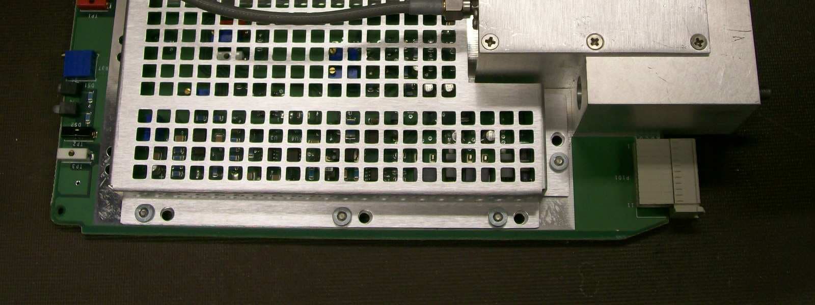
JF6-8702-50
Apr 26, 2010MDR-8000
Equipment Class
TNB - Licensed Non-Broadcast Station Transmitter
JF6-9558H
Jan 03, 2010MPT-HL Packet Terminal
Equipment Class
DTS - Digital Transmission System