JF6-8705U-155Digital Modulated Radio
Alcatel USA Marketing, Inc.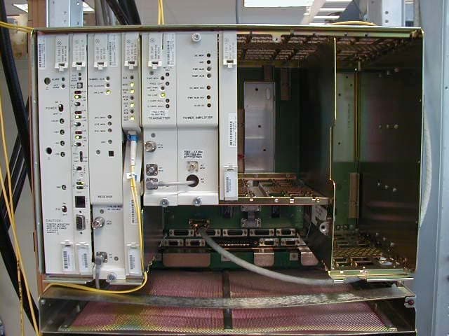
Click to zoom
Application Details
- Equipment Class
- DTS - Digital Transmission System
- Date of Grant
- Sep 05, 2005
- Application Purpose
- Original Equipment
- Date of Application
- Jul 05, 2005
- Equipment Note
- Digital Modulated Radio
- Frequency Range
- 5725.00000000 - 5850.00000000
- Company
- Alcatel USA Marketing, Inc.
- Country
- United States
Documents & Files
Document Text
Text extracted from the exhibit documents filed with the FCC. Open a document above to read the original.
Users Manual
MDR-8000/i/s/u Alcatel Part Number 3EM15726AA 3400 West Plano Parkway Plano, Texas 75075-5813 U.S.A. Part 1 of 2 Issue 2, June, 2004 Microwave Digital Radios Users Manual Table of Contents TOC-i Page Section 1General 1.1 INTRODUCTION ............................................................................................. 1-1 1.2 CONTENT ....................................................................................................... 1-1 Section 2Operation 2.1 GENERAL ........................................................................................................ 2-1 2.2 TURN-ON ........................................................................................................ 2-1 2.3 USER SYSTEM INTERFACE (USI) PROVISIONING FUNCTION/OPERATION ...... 2-2 2.4 OPERATING PROCEDURES .............................................................................. 2-2 2.4.1 Radio Receiver Manual Switching ..................................................................... 2-2 2.4.2 Radio Transmitter Manual Switching ................................................................. 2-5 2.4.3 Radio I/O Interface Manual Switching .............................................................. 2-5 2.4.4 MCS-11 Operation .......................................................................................... 2-7 2.4.5 Lamp Tests ....................................................................................................... 2-8 2.4.6 Alarm Checks .................................................................................................. 2-8 2.4.7 Orderwire Operation ....................................................................................... 2-8 2.4.8 Initiating Outgoing Orderwire Calls .................................................................. 2-8 2.4.9 Answering Incoming Orderwire Calls ................................................................ 2-8 2.5 TURN-OFF PROCEDURE ................................................................................... 2-9 2.6 EMERGENCY OPERATION .............................................................................. 2-9 2.7 MODEM OPERATION ...................................................................................... 2-9 2.8 CONTROLS, INDICATORS, TEST POINTS, AND CONNECTORS ....................... 2-9 Section 3Interconnect 3.1 SECTION INTRODUCTION .............................................................................. 3-1 3.2 INSTALL POWER CABLE ASSEMBLIES ............................................................... 3-1 Page TOC-ii 3.3 PDU STRAPPING AND CONNECTIONS ........................................................... 3-3 3.4 SHELF/RACK ALARM CONNECTION .............................................................. 3-5 3.5 DS1 CONNECTIONS (J303 IN AND J304 OUT) .............................................. 3-8 3.6 DS1 REPEATER (J314 ON ONE SHELF TO J314 ON SECOND SHELF) ............ 3-10 3.7 DS3 LBO STRAPPING AND CONNECTIONS ................................................. 3-11 3.8 DS3 LBO DS3 BNC CONNECTIONS (J21 THROUGH J26 ) ............................. 3-12 3.9 DS3 LBO WAYSIDE DS1 CONNECTIONS (J201 IN AND J202 OUT ) ............. 3-13 3.9.1 Wayside DS1 Terminal .................................................................................. 3-14 3.9.2 Wayside DS1 Repeater .................................................................................. 3-15 3.10 DS3 REPEATER (J401 ON ONE SHELF TO J401 ON SECOND SHELF) ............ 3-15 3.11 FIBER OPTIC CABLE CONNECTIONS ............................................................. 3-16 3.11.1 2 or 4 Fiber Management Panel ..................................................................... 3-17 3.11.2 2x4 Fiber Switched Management Panel .......................................................... 3-17 3.12 OC3 AUX INTERFACE BOARD WAYSIDE DS1 CONNECTIONS (J201 IN AND J202 OUT) .............................................................................. 3-20 3.12.1 Wayside DS1 Terminal .................................................................................. 3-20 3.12.2 Wayside DS1 Repeater .................................................................................. 3-20 3.13 OC3 REPEATER (J203 ON ONE SHELF TO J203 ON SECOND SHELF) ........... 3-21 3.14 USI/CONTROLLER CABLE CONNECTION TO LAPTOP (J301) ......................... 3-22 3.15 SERVICE CHANNEL ....................................................................................... 3-22 3.15.1 Handset Jack ................................................................................................. 3-23 3.15.2 Service Channels Provisioning Options ............................................................ 3-24 3.15.3 Audio 1, Audio 2 (J316, J317) ....................................................................... 3-24 3.15.4 RS-232-1, RS-232-2 (J312, J313) .................................................................... 3-27 3.15.5 MCS-11 Connections ..................................................................................... 3-28 3.15.6 ELMC (J315, J318) ........................................................................................ 3-37 3.16 FOREIGN ALARM INTERFACE (J305) ............................................................. 3-41 3.17 ALARM, STATUS, CONTROLS INTERCONNECT ............................................. 3-44 3.17.1 Controller Bus ................................................................................................ 3-46 3.17.2 Control Inputs ................................................................................................ 3-46 3.17.3 Station Alarm Inputs/TBOS Interface ............................................................... 3-46 Page TOC-iii 3.17.4 Station Alarm Wiring ..................................................................................... 3-47 3.17.5 Relay Alarm/Status Outputs .............................................................…
Text truncated - open the document above for the full version.
Users Manual
MDR-8000/i/s/u Alcatel Part Number 3EM15726AA 3400 West Plano Parkway Plano, Texas 75075-5813 U.S.A. Part 2 of 2 Issue 2, June, 2004 Microwave Digital Radios Users Manual 4-1 4 INITIAL TURNUP 4.1 SECTION INTRODUCTION This section describes the procedures required to turn up the MDR-8000 Microwave Digital Radios after installation. This provisioning part of the section describes provisioning options available with the MDR-8000 software application. Provisioning allows for the definition, editing, and storing of specific functions. The MDR-8000 provides the ability to provision equipment and facili- ties through a series of Windows™-based screens and messages. The Provisioning menu lists equipment and functions which may be provisioned. You should use only those provi- sioning screens that are applicable to your radio. Refer to the Users Guide section and applicable DS1/E1, DS3, or OC3 Initial Turnup section on the attached CD for more infor- mation. 4.2 RECOMMENDED SEQUENCE Perform the following initial turnup procedures in sequence: 1 Install software on PC. Software installed at the factory before delivery should not be overwrit- ten by downloading to the radio controller at initial turnup. Refer to Maintenance section on the attached CD for procedure to upgrade exist- ing software. 2 Establish communication between radio and USI computer. Saving provisioning on disk provides a reference for any future provi- sioning changes. 3 Provision radio. See Figure 4-1. The radio has been properly aligned and tested at the factory before shipment eliminating the need for testing after initial turn-up. The only time testing and/or adjustment is required is after a maintenance action such as removal and replacement procedure and/or constant alarms requiring corrective maintenance action. The completed maintenance action procedure(s) will reference any required test procedure(s). Note Note 4-2 Figure 4-1 Provisioning Sequence FIG 4-5 DS3 RADIO CONFIG PROVISIONING FIG 4-2 DS1/E1, DS3, OC3 RADIO CONFIG PROVISIONING FIG 4-6 DS3 FACILITIES PROVISIONING FIG 4-3 DS1/E1 RADIO CONFIG PROVISIONING FIG 4-4 DS1/E1 FACILITIES PROVISIONING FIG 4-8 OC3 RADIO CONFIG PROVISIONING FIG 4-9 OC3 FACILITIES PROVISIONING FIG 4-10 OC3 RADIO WAYSIDE DS1 FACILITIES PROVISIONING FIG 4-7 DS3 RADIO WAYSIDE DS1 FACILITIES PROVISIONING FIG 4-11 DS1/E1, DS3, OC3 RADIO SERVICE CHANNEL PROVISIONING FIG 4-12 DS1/E1, DS3, OC3 RADIO AUDIO PROVISIONING FIG 4-13 DS1/E1, DS3, OC3 RADIO MCS-11 PROVISIONING FIG 4-14 DS1/E1, DS3, OC3 RADIO MCS TRANSPORT/PPP TRANSPORT PROVISIONING FIG 4-17 DS1/E1, DS3, OC3 RADIO CONTROL NAMES PROVISIONING START OPTIONAL ENTRY LMW-9038-sm 05/07/04 FIG 4-16 DS1/E1, DS3, OC3 RADIO ELMC REMOTE TIME-OUT CONSTANT PROVISIONING FIG 4-18 DS1/E1, DS3, OC3 RADIO STATION ALARM NAMES PROVISIONING END OPTIONAL ENTRY FIG 4-15 DS1/E1, DS3, OC3 RADIO ELMC PROVISIONING DS1/E1DS3OC3 4-3 4.3 PROVISIONING RADIO Screen shown is for DS1 Radio. DS3 and OC3 radio configuration pro- visioning is similar. Changes to provisioning do not have to be made in any particular order. Open radio provisioning screens. On main screen, double click on tower icon. Status and alarm screen displays. Click on Provisioning. Check current provisioning and change as required. Figure 4-2 DS1/E1, DS3, OC3 Radio Configuration Provisioning (Sheet 1 of 4) Note ATPC EnabledA&B PA Present RADIO CONFIG: HS Tx/HS RxTERMINAL 6-8 GHz SYSTEM ALARM Visual/AudibleRelays ON/NOStation Alarm 13-16RSL Alarm Enable RSL-Sw EnableEye BER Disable RCV SWITCHING: RADIO TYPE: MDR-8000 DS116 LINES128 TCM OPTIONS: Stat/Prov/WaySideOption Key: SYSTEM ID: TEST1 Disable RADIO LINK ID:ELMC: SELECT DISABLE OR DOUBLE CLICK TO ENABLE (00 DISPLAYS). ENTER 2-DIGIT NUMBER BETWEEN 00 AND 99 AS IDENTIFICATION FOR RADIO RCV/XMT PAIR. USE FOR FREQUENCY COORDINATION IN CONGESTED AREAS THAT HAVE NEARBY TRANSMITTERS AT SAME FREQUENCY WITH SAME MODULATION. ID MUST BE SAME AT BOTH ENDS OF HOP. IF RCV ID DOES NOT MATCH ID RECEIVED FROM FAR-END XMTR, A USI ALARM AND RACK ALARM ARE GENERATED. DISPLAYS NUMBER OF LINES AVAILABLE AS DETERMINED BY CAPACITY KEY. CHANGING NUMBER OF LINES REQUIRES CHANGING CAPACITY KEY. SELECT APPROXIMATE ERROR RATE AT WHICH EYE CLOSURE ALARM ACTIVATES AND SWITCHING OCCURS: EYE BER=1X10 -5 , 1X10 -6 , 1X10 -7 , 1X10 -8 OR SELECT Eye BER Disable TO ACTIVATE ALARMS AT APPROXIMATELY 1X10⁻⁶ WITHOUT RECEIVERS SWITCHING. SELECT A&B PA Present IF SHELF IS EQUIPPED WITH A&B PAs, A OR B PA ONLY IF SHELF IS EQUIP- PED WITH ONLY ONE PA, OR NO PA IF SHELF IS NOT EQUIPPED WITH PA. UNEQUIPPED PA ALARMS ARE DISABLED. SELECT Major/Minor TO TRIGGER MAJOR ALARM ON ANY ALARM ON ON-LINE SIDE AND MINOR ALARM ON ANY ALARM ON OFF-LINE SIDE. SELECT Visual/ Audible TO TRIGGER RACK ALARM ON ANY ALARM ON ON-LINE SIDE. DISPLAYS ELMC OPTION KEY TYPE INSTALLED ON CON- TROLLER. STAT (STATUS)/PROV (REMOTE PROVISIONING)/ WAYSIDE (WITH WAYSIDE DS1 MONITORING). NOT PRO- VISIONABLE. CHANGING DISPLAY REQUIRES CHANGING OPTION KEY. SELECT TERMINAL, REPEATER, RING TERMINAL OR RING REPEATER FROM DROP DOWN LIST. SELECT REPEATER IF TRAFFIC AND SERVICE CHANNEL (FOUR RAILS OF X/Y DATA) ARE BEING TRANSPORTED BETWEEN J314 OF BOTH SHELVES. ENABLE OR DISABLE AUTOMATIC POWER CONTROL (ATPC) FUNCTION. SELECT ATPC Disable, ATPC Enabled, OR ATPC with Timeout FROM DROP DOWN LIST. SEE SHEET 2 0F 3 FOR DETAILS. DISPLAYS MODULATION SCHEME. NOT PROVISIONABLE DISPLAYS RADIO TYPE NOT PROVISIONABLE BACKSPACE TO DELETE CURRENT ADDRESS AND ENTER 5-DIGIT REMOTE RACK ADDRESS. SEE FIGURE 6-11 FOR DETAILS. SELECT RSL-Sw Enable TO ENABLE AUTOMATIC RECEIVER SWITCHING BASED ON RSL. WHEN ENABLED, RECEIVER SWITCHES IF: 1. ON-LINE RCV RSL IS BELOW RCV AGC THRESHOLD, AND 2. OFF-LINE RCV RSL IS ABOVE RCV AGC THRESHOLD. SELECT RSL-Sw Disable TO DISABLE AUTOMATIC RECEIVER SWITCHING. LMW-7084 Sheet 1 of 2 02/04/03 SELECT Station Alarm 13-16 TO ENABLE STATION ALARM 13-16 INPUTS TO RELAY INTFC. WHEN EXTERNAL TBOS IS WIRED TO RADIO, SELECT TBOS Display 1-…
Text truncated - open the document above for the full version.
Block Diagram
APPLICATION FOR FCC CERTIFICATION ALCATEL USA Digitally Modulated Radio MODEL FCC ID MDR-8705u-155 JF6-8705u-155 Number of Pages: 32 Date of Report: January 18, 2005 - 1 - FCC Part 15.247 Digital Modulation Technique Certification Alcatel 1000 Coit Rd., Plano, Texas, 75075 - 2 - FCC Part 15.247 Digital Modulation Technique Certification Alcatel 1000 Coit Rd., Plano, Texas, 75075 3.3.1 OC3 I/O Subsystem Functional Description The OC3 STM-1 subsystem consists of the AUX interface board and the I/O interface modules. The I/O subsystem interfaces the XMT and RCV and monitor and control subsystems. The OC3 I/O subsystem converts OC3 STM-1 signals to digital signals and multiplexes this data with overhead data. Multiplexed data is demultiplexed to separate the overhead data from the data stream.
External Photos
External Photos MDR8705u-XX radio mounted in a rack with over on. MDR-8705u-XX radio (non-standby) without cover.
ID Label/Location Info
APPENDIX A: FCC ID Location
ID Label/Location Info
To: Linda Elliott, Correspondence Reference Number: 29415 731 Confirmation Number: EA345054 I have four applications in the process of being reviewed for equipment authorization. FCC ID: JF68705U-155 Form 731 Confirmation: EA345054 FCC ID: JF68705U-52 Form 731 Confirmation: EA607031 FCC ID: JF68705U-16 Form 731 Confirmation: EA299647 FCC ID: JF68705U-8 Form 731 Confirmation: EA244352 I had several problems trying to input information to the online applications. One being the FCC ID, our company ID is JF6 and the equipment type should be followed by a hyphen. The above FCC IDs need to be changed to add a hyphen between the company (grantee) ID and the equipment type as indicated below: FCC ID: JF6-8705U-155 FCC ID: JF6-8705U-52 FCC ID: JF6-8705U-16 FCC ID: JF6-8705U-8 Could you make these changes to my applications? Please call if you need any additional clarification, information or if it's going to delay the applications. Thanks, Troy Taylor Alcatel NA, WTD 972-519-4377
Internal Photos
OC3 Interface Card (Front View) OC3 Interface Card (Back View)
Operational Description
- 1 - FCC Part 15.247 Digital Modulation Technique Certification Alcatel 1000 Coit Rd., Plano, Texas, 75075 1.0 Operational Description The MDR-8705-XX is the MDR-8000/i/s/u version for the unlicensed frequency band: 5725-5850 MHz. It is the latest addition of the Alcatel family of digital microwave products. The MDR-8705-XX radio capacity is OC3 which as a Transport Capacity of 155 Mb/s. The OC3 I/O and the Ethernet I/O baud rates are the same as well as the Transport Capacity of 155 Mb/s and modulation. The MDR–8000/i/s/u series Microwave Digital Radios (see figure 2–1) consists of: · Solid–state, licensed, digital radios that provide transport for DS1, E1, and DS3 in 2, 4, 6, 7, 8, 10, and 11 GHz RF frequency bands and OC3 in 4, 6, 7, 8, 10, and 11 GHz RF frequency bands · Solid–state, unlicensed digital radios that provide transport for DS1, DS3 and OC3 in the 5 GHz RF frequency band. The following capacities and modulation schemes are available: · MDR–8000 – 2, 4, 8, 12, or 16 North American Standard DS1 channels at either 32 or 128 TCM, 1 or 3 North American Standard DS3 channels with 1 or 3 wayside DS1 channels at 64 QAM · MDR–8000i – 2, 4, 8, 12, or 16 CCITT E1 channels at either 32 or 128 TCM · MDR–8000s – 3 North American Standard STS1 channels with 3 wayside DS1 channels at 128 TCM · MDR–8000u– 2, 4, 8, or 16 North American Standard DS1 channels at 32 TCM, 1 North American Standard DS3 channel with 1 wayside DS1 channel at 16 or 64 QAM and 1 North American Standard OC3 channel with 3 way sides DS1 channels at 128 TCM. The radio fits into a standard 19 in. (483 mm) rack and occupies seven vertical rack increments. Up to four fully–equipped hot–standby radios can be mounted in a standard 7 ft rack. The radio is front accessible and can be mounted against a wall or back–to–back against other equipment. 1.1 STANDARD FEATURES Standard features include: · Frequency bands from 2 to 11 GHz - 2 - FCC Part 15.247 Digital Modulation Technique Certification Alcatel 1000 Coit Rd., Plano, Texas, 75075 · Committee of European Post and Telegraph (CEPT)/Federal Communications Commission (FCC) applications · DS1, E1, DS3, Ethernet and OC3 Traffic capacities. · International Telecommunications Union (ITU)/ETSI/FCC compliant · Five configuration options · Upstream management compatibility · User–friendly Personal Computer (PC) monitor and control · Automatic Transmitter Power Control (ATPC) · Adaptive Time Domain Equalization (TDE) · Extended Link Monitor Channel (ELMC) · MCS–11/Telemetry Byte Oriented Serial (TBOS) Alarm/Control Interface · Two independent PCM audio channels - 3 - FCC Part 15.247 Digital Modulation Technique Certification Alcatel 1000 Coit Rd., Plano, Texas, 75075 Figure 2–1 Typical MDR–8000/i/s/u Series Microwave Digital Radio - 4 - FCC Part 15.247 Digital Modulation Technique Certification Alcatel 1000 Coit Rd., Plano, Texas, 75075 1.2 NAMING CONVENTION The MDR–8000/i/s/u series radio naming conventions are as follows: - 5 - FCC Part 15.247 Digital Modulation Technique Certification Alcatel 1000 Coit Rd., Plano, Texas, 75075 1.3 SYSTEM CONFIGURATIONS The MDR–8000/i/s radio can be provisioned as a terminal, synchronous repeater, ring terminal, or ring repeater. 1.4 RADIO CONFIGURATIONS 1.4.1 Basic Configurations The MDR–8000/i/s/u supports the three basic configurations: · Non–standby – available in all frequency bands – stand alone transmitter/receiver combination · Hot–standby – available in all frequency bands – pair of transmitters and receivers, both pairs operating on the same set of go and return frequencies. · Frequency diversity – available in all frequency bands except 2 GHz – pair of transmitters and receivers, each pair operating on a different set of go and return frequencies. 1.4.2 Ring Non–standby radios are typically used in ring systems where the radios are protected by the ring architecture. 1.4.3 Space Diversity Add–On Space diversity can be added to any of the three basic configurations and ring systems. 1.4.4 Optical 2 X 4 Configuration Hot–standby and frequency diversity configuration are available with 2–fiber or 4–fiber optical interfaces. 1.5 FEATURES AND OPTIONS Features and options for the MDR–8000/i/s/u series of microwave digital radios are described in the following paragraphs. 1.5.1 Primary Power The MDR–8000/i/s/u series radios operate from 20.5 to 60 V dc primary power with positive or negative ground. - 6 - FCC Part 15.247 Digital Modulation Technique Certification Alcatel 1000 Coit Rd., Plano, Texas, 75075 1.5.2 Transmit Power Level Options The standard radio is provided without a power amplifier (PA) module for low–power applications. The optional PA module is available for high–power requirements. There are different levels for the different frequency bands. Refer to the electrical characteristics table in this section for specific levels. 1.5.3 Differential Absolute Delay Equalization (DADE) DADEing adjusts the differential absolute delay between the main and diversity signals in a space diversity configuration. DADEing is an automatic function within the MDR–8000/i/s/u receivers, reducing the time required for initial turn–up and test. 1.5.4 Trellis Encoding and Time Domain Equalization (TDE) Trellis encoding (DS1/E1/OC3) ensures that even with the most severe multipath, only the correct digital data is demodulated. TDE further reduces the disruptive effects of multipath distortion. 1.5.5 MCS–11 Alarm/Control Interface MCS–11 is standard in the MDR–8000. The MDR–8000 can interface with any alarm system that is based on the MCS–11 protocol. Use with the TSM–2500 network management system to develop a central access point to monitor and control the transmission system 1.5.6 Foreign Alarm Interface This provisioning option provides serial alarm/status reporting for the Telemetry Byte Oriented Serial (TBOS) protocol. A wire–wrap adapter is provided to mate to connector J305 on the backplane. 1.5.7 Relay Interface Option The optional AE–27AF Re…
Text truncated - open the document above for the full version.
Parts List/Tune Up Info
Alcatel 3400 Plano Parkway, Plano, Texas, 75075 ALCATEL USA WIRELESS TRANSMISSION DEVISION 3400 West Plano Parkway Rd. M/S WLS1 Pano, Tx 75075 Andrew Leimer FCC Application Processing Branch Federal Communications Commission RE: Response to FCC Requests Correspondence Reference Numbers: 29295 FCC IDs: JF6-8705U-155 Form 731 Confirmation Number: EA345054 Dear Mr. Leimer: The following are Alcatel’s responses to the questions presented in your recent e-mail, dated July 29, 2005: Question 1: What antennas are to be used and marketed with this device? Give the manufacturer’s name, model number, antenna type, mainbeam gain, and supply a photo of each antenna. The proposed JF6-8705U-155 radio will use the same antennas as five lower capacity radios that were granted equipment authorization in November of 2002. These radios are the JF6-8505U-2, JF6-8505U-4, JF6-8505U-8, JF6-8505U-16, and JF6-8605U-45. The Grant Notes for the JF6-8505U-4 states: Output is peak conducted. This grant is valid only when the radio is used and marketed with 2ft – 10ft parabolic antennas or 1ft and 2ft flat panels as indicated in the Certification filing. The device must be professionally installed. The antenna(s) used for this transmitter must be fixed-mounted on outdoor permanent structures and must not be co-located or operating in conjunction with any other antenna or transmitter. The separation distance for the 1 ft flat panel must be at least 5 feet from all persons. Users and installers must be provided with antenna installation and transmitter operating conditions for satisfying RF exposure compliance. The proposed JF6-8705U-155 will use 2 foot to 10 foot diameter parabolic or 1 foot and 2 foot flat panel antennas. Figures 1 and 2 list typical parabolic and flat panel antennas from Andrew Corporation and Radio Frequency Systems, which is a division of Alcatel. Figures 3 and 4 show photos of the antennas. Parabolic and flat panel antennas from other manufacturers typically have antenna gains within a few tenths of a dB, as compared to the antennas listed in the attached tables. Alcatel 3400 Plano Parkway, Plano, Texas, 75075 There are a large variety of parabolic and flat panel antennas available for different applications. Standard performance dishes may be purchased with a spherical or conical radome cover to reduce wind loading and protect the antenna from snow and icing conditions. High performance and ultra-high performance parabolic antennas have a shroud and integrated flat radome on the front of the dish to improve the antenna discrimination characteristics. Some antennas cover a wide frequency range, including the FCC Part 101 bands from 5.925-6.425 GHz and 6.525-6.875 GHz. Using these antennas, it is possible to convert the radio from unlicensed Part 15 to licensed Part 101 operation without an antenna change. The change to licensed operation requires frequency coordination in the licensed band under Part 101 rules. The radios are sold without an antenna. The operator selects the antenna type, model, and size from commercial antenna manufacturers, as permitted by the equipment authorization. Antennas must be professionally installed. Question 2: How does this device meet the unique antenna requirements to Section 15.203? Section 15.203 states: An intentional radiator shall be designed to ensure that no antenna other than that furnished by the responsible party shall be used with the device. The use of a permanently attached antenna or of an antenna that uses a unique coupling to the intentional radiator shall be considered sufficient to comply with the provisions of this section. ... Further, this requirement does not apply to intentional radiators that must be professionally installed, ... The JF6-8705U-155 radio will be used exclusively for fixed point-to-point communications. Antennas will be mounted outdoors, usually on a tower. The antennas have narrow beamwidths and require a professional installer for alignment. Since the JF6-8705U-155 radio must be professionally installed, the unique antenna requirements of Section 15.203 do not apply. 3) The Test report indicates that there is a power amplifier option. Was this device tested with this option? Yes, the product was tested with the optional power amplifier; the maximum power amplifier provides the maximum output power (1Watt) at the antenna port. Please let me know if there is any other information we need to provide to expedite the technical review process. Yours truly, Troy Taylor Product Line Manager Wireless Transmission Division
Parts List/Tune Up Info
Antenna Manufacturer's Name: Radio Frequency Systems Division of Alcatel Antenna Antenna Mainbeam Antenna Single or Lowest Highest Beam Cross Pol Front-to- Model Type Gain Diameter Dual RF Freq RF Freq Width Discrimination Back Ratio Description Number dBi feet Polarized MHz MHz dB dB dB SPF2-52B Parabolic 28.5 2 Single 5250 5850 5.8 30 43 Standard Performance, SlimLine, Non-Pressurized SPF3-52B Parabolic 32.0 3 Single 5250 5850 3.9 30 45 Standard Performance, SlimLine, Non-Pressurized SPF4-52B Parabolic 34.4 4 Single 5250 5850 3.0 30 48 Standard Performance, SlimLine, Non-Pressurized SPF6-52B Parabolic 38.1 6 Single 5250 5850 2.0 30 50 Standard Performance, SlimLine, Non-Pressurized PSF8-57A Parabolic 40.4 8 Single 5725 5850 1.7 25 46 Standard Performance, Non-Pressurized PSF10-57A Parabolic 42.7 10 Single 5725 5850 1.4 25 49 Standard Performance, Non-Pressurized MA0528-23A Flat Panel 23.0 1 Single 5725 5875 9.0 28 35 Flat Panel, Non-Pressurized MA0528-28A Flat Panel 28.0 2 Single 5725 5875 4.5 28 45 Flat Panel, Non-Pressurized MAX0528-23A Flat Panel 23.0 1 Dual 5725 5875 9.0 30 30 Flat Panel, Non-Pressurized PA4-57A Parabolic 34.8 4 Single 5725 5850 3.1 30 42 Standard Performance PA6-57A Parabolic 38.3 6 Single 5725 5850 2.1 30 46 Standard Performance PA8-57A Parabolic 40.8 8 Single 5725 5850 1.5 30 48 Standard Performance PA10-57A Parabolic 42.7 10 Single 5725 5850 1.2 30 51 Standard Performance SDF4-52B Parabolic 34.4 4 Single 5250 5850 3.0 30 58 High Performance, SlimLine, Non-Pressurized SDF6-52B Parabolic 38.1 6 Single 5250 5850 2.0 30 61 High Performance, SlimLine, Non-Pressurized DA4-57A Parabolic 34.8 4 Single 5725 5850 3.1 30 55 High Performance DA6-57A Parabolic 38.3 6 Single 5725 5850 2.1 30 64 High Performance DA8-57A Parabolic 40.8 8 Single 5725 5850 1.5 30 68 High Performance DA10-57A Parabolic 42.7 10 Single 5725 5850 1.2 30 70 High Performance UA6-56A Parabolic 38.5 6 Single 5670 6170 2.0 30 66 Ultra High Performance UA8-56A Parabolic 41.0 8 Single 5670 6170 1.5 30 69 Ultra High Performance UA10-56A Parabolic 42.9 10 Single 5670 6170 1.2 30 71 Ultra High Performance PAX6-56A Parabolic 38.4 6 Dual 5670 6170 2.0 30 46 Standard Performance PAX8-56A Parabolic 40.9 8 Dual 5670 6170 1.5 30 48 Standard Performance PAX10-56A Parabolic 42.8 10 Dual 5670 6170 1.2 30 50 Standard Performance DAX6-56A Parabolic 38.4 6 Dual 5670 6170 2.0 30 59 High Performance DAX8-56A Parabolic 40.9 8 Dual 5670 6170 1.5 30 67 High Performance DAX10-56A Parabolic 42.8 10 Dual 5670 6170 1.2 30 69 High Performance UDA6-56A Parabolic 38.4 6 Dual 5670 6170 2.0 30 66 Ultra High Performance UDA8-56A Parabolic 40.9 8 Dual 5670 6170 1.5 30 70 Ultra High Performance UDA10-56A Parabolic 42.8 10 Dual 5670 6170 1.2 30 72 Ultra High Performance Figure 1 Antenna Manufacturer's Name: Radio Frequency Systems Division of Alcatel Antenna Antenna Mainbeam Antenna Single or Lowest Highest Beam Cross Pol Front-to- Model Type Gain Diameter Dual RF Freq RF Freq Width Discrimination Back Ratio Description Number dBi feet Polarized MHz MHz dB dB dB UXA6-56A Parabolic 38.4 6 Dual 5670 6170 2.0 40 68 Ultra High Performance, High XPD UXA8-56A Parabolic 40.9 8 Dual 5670 6170 1.5 40 70 Ultra High Performance, High XPD UXA10-56A Parabolic 42.8 10 Dual 5670 6170 1.2 40 72 Ultra High Performance, High XPD PAD6-W57A Parabolic 38.9 6 Single 5725 6875 1.9 30 55 Standard Performance, FCC Part 101 Category A PAD8-W57A Parabolic 41.4 8 Single 5725 6875 1.4 30 57 Standard Performance, FCC Part 101 Category A PA4-W57A Parabolic 35.5 4 Single 5725 6875 2.8 28 42 Standard Performance PA6-W57A Parabolic 39.0 6 Single 5725 6875 1.9 30 46 Standard Performance PA8-W57A Parabolic 41.5 8 Single 5725 6875 1.4 30 48 Standard Performance PA10-W57A Parabolic 43.5 10 Single 5725 6875 1.1 30 51 Standard Performance DA4-W57A Parabolic 35.5 4 Single 5725 6875 2.8 28 55 High Performance DA6-W57A Parabolic 39.0 6 Single 5725 6875 1.9 30 64 High Performance DA8-W57A Parabolic 41.5 8 Single 5725 6875 1.4 30 68 High Performance DA10-W57A Parabolic 43.5 10 Single 5725 6875 1.1 30 70 High Performance Antenna Manufacturer's Name: Andrew Corporation Antenna Antenna Mainbeam Antenna Single or Lowest Highest Beam Cross Pol Front-to- Model Type Gain Diameter Dual RF Freq RF Freq Width Discrimination Back Ratio Description Number dBi feet Polarized MHz MHz dB dB dB P2F-52 Parabolic 29.4 2 Single 5250 5850 5.4 30 41 Standard Performance, Unpressurized P3F-52 Parabolic 33.4 3 Single 5250 5850 3.8 30 42 Standard Performance, Unpressurized P4F-52 Parabolic 34.9 4 Single 5250 5850 3.0 30 52 Standard Performance, Unpressurized P6F-52 Parabolic 37.6 6 Single 5250 5850 1.8 30 49 Standard Performance, Unpressurized PX2F-52 Parabolic 29.4 2 Dual 5250 5850 5.4 30 41 Standard Performance, Unpressurized PX3F-52 Parabolic 33.4 3 Dual 5250 5850 3.8 30 42 Standard Performance, Unpressurized PX4F-52 Parabolic 34.9 4 Dual 5250 5850 3.0 30 52 Standard Performance, Unpressurized PX6F-52 Parabolic 37.6 6 Dual 5250 5850 1.8 30 49 Standard Performance, Unpressurized FPA5250D12-N Flat Panel 23.6 1 Single 5250 5850 9.6 30 38 Flat Panel FPA5250D24-N Flat Panel 28.5 2 Single 5250 5850 4.8 30 43 Flat Panel FPA5150-23PM-1 Flat Panel 23.0 1 Single 5150 5875 10.5 35 Flat Panel, Pole Mount FPA5150-16-1 Flat Panel 23.0 1 Single 5150 5875 10.5 35 Flat Panel, Adjustable Mount HP2F-52 Parabolic 29.0 2 Single 5250 5850 5.4 30 50 High Performance, Unpressurized HP3F-52…
Text truncated - open the document above for the full version.
Contact Information
Applicant
Alfred Holland(R&D Manager)
Technical Contact
Alcatel North AmericaTroy Taylor
[email protected]972-519-4377
3400 W. Plano Parkway · Plano, Texas · United States
Test Firm
Alcatel North AmericaRichard Riley
Technical Specifications
| # | Rule Parts | Frequency Range | Power Output |
|---|---|---|---|
| 1 | 15C | 5.72 GHz - 5.85 GHz | 1 W |
Other Applications from Alcatel USA Marketing, Inc.
JF6-9558L-D
May 28, 20155 GHz rack-mounted point to point transceiver
Equipment Class
DTS - Digital Transmission System
JF6-9558L
May 28, 20155 GHz rack-mounted point to point transceiver
Equipment Class
DTS - Digital Transmission System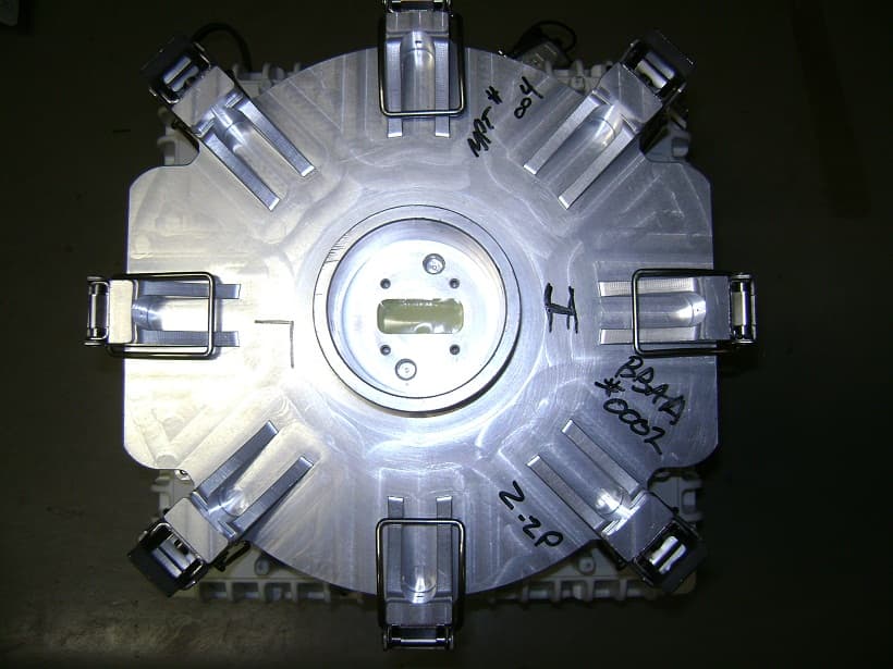
JF6-9558HC
Aug 06, 2012Microwave Packet Radio
Equipment Class
DTS - Digital Transmission System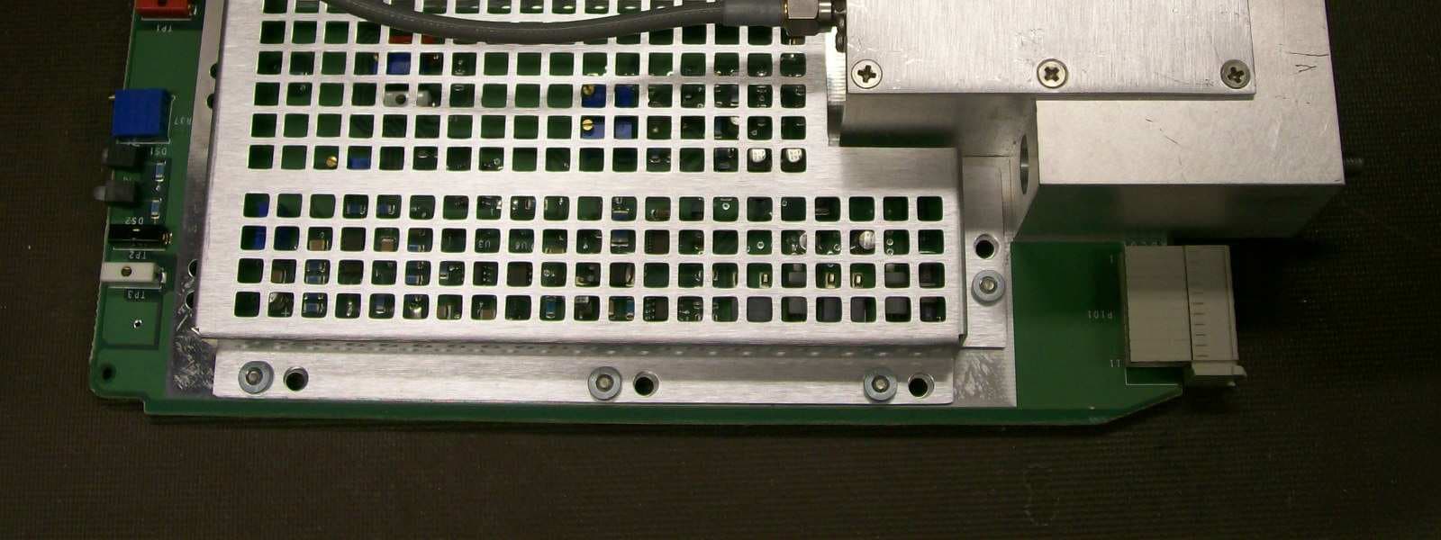
JF6-8702-50
Apr 26, 2010MDR-8000
Equipment Class
TNB - Licensed Non-Broadcast Station Transmitter
JF6-9558H
Jan 03, 2010MPT-HL Packet Terminal
Equipment Class
DTS - Digital Transmission System