JF6-8705U-16Digitally Modulated Radio
Alcatel USA Marketing, Inc.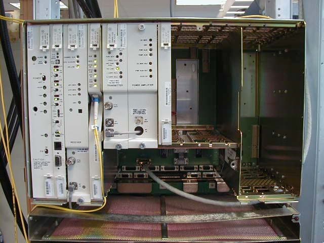
Click to zoom
Application Details
- Equipment Class
- DTS - Digital Transmission System
- Date of Grant
- Sep 29, 2005
- Application Purpose
- Original Equipment
- Date of Application
- Jul 05, 2005
- Equipment Note
- Digitally Modulated Radio
- Frequency Range
- 5725.00000000 - 5850.00000000
- Company
- Alcatel USA Marketing, Inc.
- Country
- United States
Documents & Files
Document Text
Text extracted from the exhibit documents filed with the FCC. Open a document above to read the original.
Users Manual
MDR-8000/i/s/u Alcatel Part Number 3EM15726AA 3400 West Plano Parkway Plano, Texas 75075-5813 U.S.A. Part 1 of 2 Issue 2, June, 2004 Microwave Digital Radios Users Manual Table of Contents TOC-i Page Section 1General 1.1 INTRODUCTION ............................................................................................. 1-1 1.2 CONTENT ....................................................................................................... 1-1 Section 2Operation 2.1 GENERAL ........................................................................................................ 2-1 2.2 TURN-ON ........................................................................................................ 2-1 2.3 USER SYSTEM INTERFACE (USI) PROVISIONING FUNCTION/OPERATION ...... 2-2 2.4 OPERATING PROCEDURES .............................................................................. 2-2 2.4.1 Radio Receiver Manual Switching ..................................................................... 2-2 2.4.2 Radio Transmitter Manual Switching ................................................................. 2-5 2.4.3 Radio I/O Interface Manual Switching .............................................................. 2-5 2.4.4 MCS-11 Operation .......................................................................................... 2-7 2.4.5 Lamp Tests ....................................................................................................... 2-8 2.4.6 Alarm Checks .................................................................................................. 2-8 2.4.7 Orderwire Operation ....................................................................................... 2-8 2.4.8 Initiating Outgoing Orderwire Calls .................................................................. 2-8 2.4.9 Answering Incoming Orderwire Calls ................................................................ 2-8 2.5 TURN-OFF PROCEDURE ................................................................................... 2-9 2.6 EMERGENCY OPERATION .............................................................................. 2-9 2.7 MODEM OPERATION ...................................................................................... 2-9 2.8 CONTROLS, INDICATORS, TEST POINTS, AND CONNECTORS ....................... 2-9 Section 3Interconnect 3.1 SECTION INTRODUCTION .............................................................................. 3-1 3.2 INSTALL POWER CABLE ASSEMBLIES ............................................................... 3-1 Page TOC-ii 3.3 PDU STRAPPING AND CONNECTIONS ........................................................... 3-3 3.4 SHELF/RACK ALARM CONNECTION .............................................................. 3-5 3.5 DS1 CONNECTIONS (J303 IN AND J304 OUT) .............................................. 3-8 3.6 DS1 REPEATER (J314 ON ONE SHELF TO J314 ON SECOND SHELF) ............ 3-10 3.7 DS3 LBO STRAPPING AND CONNECTIONS ................................................. 3-11 3.8 DS3 LBO DS3 BNC CONNECTIONS (J21 THROUGH J26 ) ............................. 3-12 3.9 DS3 LBO WAYSIDE DS1 CONNECTIONS (J201 IN AND J202 OUT ) ............. 3-13 3.9.1 Wayside DS1 Terminal .................................................................................. 3-14 3.9.2 Wayside DS1 Repeater .................................................................................. 3-15 3.10 DS3 REPEATER (J401 ON ONE SHELF TO J401 ON SECOND SHELF) ............ 3-15 3.11 FIBER OPTIC CABLE CONNECTIONS ............................................................. 3-16 3.11.1 2 or 4 Fiber Management Panel ..................................................................... 3-17 3.11.2 2x4 Fiber Switched Management Panel .......................................................... 3-17 3.12 OC3 AUX INTERFACE BOARD WAYSIDE DS1 CONNECTIONS (J201 IN AND J202 OUT) .............................................................................. 3-20 3.12.1 Wayside DS1 Terminal .................................................................................. 3-20 3.12.2 Wayside DS1 Repeater .................................................................................. 3-20 3.13 OC3 REPEATER (J203 ON ONE SHELF TO J203 ON SECOND SHELF) ........... 3-21 3.14 USI/CONTROLLER CABLE CONNECTION TO LAPTOP (J301) ......................... 3-22 3.15 SERVICE CHANNEL ....................................................................................... 3-22 3.15.1 Handset Jack ................................................................................................. 3-23 3.15.2 Service Channels Provisioning Options ............................................................ 3-24 3.15.3 Audio 1, Audio 2 (J316, J317) ....................................................................... 3-24 3.15.4 RS-232-1, RS-232-2 (J312, J313) .................................................................... 3-27 3.15.5 MCS-11 Connections ..................................................................................... 3-28 3.15.6 ELMC (J315, J318) ........................................................................................ 3-37 3.16 FOREIGN ALARM INTERFACE (J305) ............................................................. 3-41 3.17 ALARM, STATUS, CONTROLS INTERCONNECT ............................................. 3-44 3.17.1 Controller Bus ................................................................................................ 3-46 3.17.2 Control Inputs ................................................................................................ 3-46 3.17.3 Station Alarm Inputs/TBOS Interface ............................................................... 3-46 Page TOC-iii 3.17.4 Station Alarm Wiring ..................................................................................... 3-47 3.17.5 Relay Alarm/Status Outputs .............................................................…
Text truncated - open the document above for the full version.
Users Manual
MDR-8000/i/s/u Alcatel Part Number 3EM15726AA 3400 West Plano Parkway Plano, Texas 75075-5813 U.S.A. Part 2 of 2 Issue 2, June, 2004 Microwave Digital Radios Users Manual 4-1 4 INITIAL TURNUP 4.1 SECTION INTRODUCTION This section describes the procedures required to turn up the MDR-8000 Microwave Digital Radios after installation. This provisioning part of the section describes provisioning options available with the MDR-8000 software application. Provisioning allows for the definition, editing, and storing of specific functions. The MDR-8000 provides the ability to provision equipment and facili- ties through a series of Windows™-based screens and messages. The Provisioning menu lists equipment and functions which may be provisioned. You should use only those provi- sioning screens that are applicable to your radio. Refer to the Users Guide section and applicable DS1/E1, DS3, or OC3 Initial Turnup section on the attached CD for more infor- mation. 4.2 RECOMMENDED SEQUENCE Perform the following initial turnup procedures in sequence: 1 Install software on PC. Software installed at the factory before delivery should not be overwrit- ten by downloading to the radio controller at initial turnup. Refer to Maintenance section on the attached CD for procedure to upgrade exist- ing software. 2 Establish communication between radio and USI computer. Saving provisioning on disk provides a reference for any future provi- sioning changes. 3 Provision radio. See Figure 4-1. The radio has been properly aligned and tested at the factory before shipment eliminating the need for testing after initial turn-up. The only time testing and/or adjustment is required is after a maintenance action such as removal and replacement procedure and/or constant alarms requiring corrective maintenance action. The completed maintenance action procedure(s) will reference any required test procedure(s). Note Note 4-2 Figure 4-1 Provisioning Sequence FIG 4-5 DS3 RADIO CONFIG PROVISIONING FIG 4-2 DS1/E1, DS3, OC3 RADIO CONFIG PROVISIONING FIG 4-6 DS3 FACILITIES PROVISIONING FIG 4-3 DS1/E1 RADIO CONFIG PROVISIONING FIG 4-4 DS1/E1 FACILITIES PROVISIONING FIG 4-8 OC3 RADIO CONFIG PROVISIONING FIG 4-9 OC3 FACILITIES PROVISIONING FIG 4-10 OC3 RADIO WAYSIDE DS1 FACILITIES PROVISIONING FIG 4-7 DS3 RADIO WAYSIDE DS1 FACILITIES PROVISIONING FIG 4-11 DS1/E1, DS3, OC3 RADIO SERVICE CHANNEL PROVISIONING FIG 4-12 DS1/E1, DS3, OC3 RADIO AUDIO PROVISIONING FIG 4-13 DS1/E1, DS3, OC3 RADIO MCS-11 PROVISIONING FIG 4-14 DS1/E1, DS3, OC3 RADIO MCS TRANSPORT/PPP TRANSPORT PROVISIONING FIG 4-17 DS1/E1, DS3, OC3 RADIO CONTROL NAMES PROVISIONING START OPTIONAL ENTRY LMW-9038-sm 05/07/04 FIG 4-16 DS1/E1, DS3, OC3 RADIO ELMC REMOTE TIME-OUT CONSTANT PROVISIONING FIG 4-18 DS1/E1, DS3, OC3 RADIO STATION ALARM NAMES PROVISIONING END OPTIONAL ENTRY FIG 4-15 DS1/E1, DS3, OC3 RADIO ELMC PROVISIONING DS1/E1DS3OC3 4-3 4.3 PROVISIONING RADIO Screen shown is for DS1 Radio. DS3 and OC3 radio configuration pro- visioning is similar. Changes to provisioning do not have to be made in any particular order. Open radio provisioning screens. On main screen, double click on tower icon. Status and alarm screen displays. Click on Provisioning. Check current provisioning and change as required. Figure 4-2 DS1/E1, DS3, OC3 Radio Configuration Provisioning (Sheet 1 of 4) Note ATPC EnabledA&B PA Present RADIO CONFIG: HS Tx/HS RxTERMINAL 6-8 GHz SYSTEM ALARM Visual/AudibleRelays ON/NOStation Alarm 13-16RSL Alarm Enable RSL-Sw EnableEye BER Disable RCV SWITCHING: RADIO TYPE: MDR-8000 DS116 LINES128 TCM OPTIONS: Stat/Prov/WaySideOption Key: SYSTEM ID: TEST1 Disable RADIO LINK ID:ELMC: SELECT DISABLE OR DOUBLE CLICK TO ENABLE (00 DISPLAYS). ENTER 2-DIGIT NUMBER BETWEEN 00 AND 99 AS IDENTIFICATION FOR RADIO RCV/XMT PAIR. USE FOR FREQUENCY COORDINATION IN CONGESTED AREAS THAT HAVE NEARBY TRANSMITTERS AT SAME FREQUENCY WITH SAME MODULATION. ID MUST BE SAME AT BOTH ENDS OF HOP. IF RCV ID DOES NOT MATCH ID RECEIVED FROM FAR-END XMTR, A USI ALARM AND RACK ALARM ARE GENERATED. DISPLAYS NUMBER OF LINES AVAILABLE AS DETERMINED BY CAPACITY KEY. CHANGING NUMBER OF LINES REQUIRES CHANGING CAPACITY KEY. SELECT APPROXIMATE ERROR RATE AT WHICH EYE CLOSURE ALARM ACTIVATES AND SWITCHING OCCURS: EYE BER=1X10 -5 , 1X10 -6 , 1X10 -7 , 1X10 -8 OR SELECT Eye BER Disable TO ACTIVATE ALARMS AT APPROXIMATELY 1X10⁻⁶ WITHOUT RECEIVERS SWITCHING. SELECT A&B PA Present IF SHELF IS EQUIPPED WITH A&B PAs, A OR B PA ONLY IF SHELF IS EQUIP- PED WITH ONLY ONE PA, OR NO PA IF SHELF IS NOT EQUIPPED WITH PA. UNEQUIPPED PA ALARMS ARE DISABLED. SELECT Major/Minor TO TRIGGER MAJOR ALARM ON ANY ALARM ON ON-LINE SIDE AND MINOR ALARM ON ANY ALARM ON OFF-LINE SIDE. SELECT Visual/ Audible TO TRIGGER RACK ALARM ON ANY ALARM ON ON-LINE SIDE. DISPLAYS ELMC OPTION KEY TYPE INSTALLED ON CON- TROLLER. STAT (STATUS)/PROV (REMOTE PROVISIONING)/ WAYSIDE (WITH WAYSIDE DS1 MONITORING). NOT PRO- VISIONABLE. CHANGING DISPLAY REQUIRES CHANGING OPTION KEY. SELECT TERMINAL, REPEATER, RING TERMINAL OR RING REPEATER FROM DROP DOWN LIST. SELECT REPEATER IF TRAFFIC AND SERVICE CHANNEL (FOUR RAILS OF X/Y DATA) ARE BEING TRANSPORTED BETWEEN J314 OF BOTH SHELVES. ENABLE OR DISABLE AUTOMATIC POWER CONTROL (ATPC) FUNCTION. SELECT ATPC Disable, ATPC Enabled, OR ATPC with Timeout FROM DROP DOWN LIST. SEE SHEET 2 0F 3 FOR DETAILS. DISPLAYS MODULATION SCHEME. NOT PROVISIONABLE DISPLAYS RADIO TYPE NOT PROVISIONABLE BACKSPACE TO DELETE CURRENT ADDRESS AND ENTER 5-DIGIT REMOTE RACK ADDRESS. SEE FIGURE 6-11 FOR DETAILS. SELECT RSL-Sw Enable TO ENABLE AUTOMATIC RECEIVER SWITCHING BASED ON RSL. WHEN ENABLED, RECEIVER SWITCHES IF: 1. ON-LINE RCV RSL IS BELOW RCV AGC THRESHOLD, AND 2. OFF-LINE RCV RSL IS ABOVE RCV AGC THRESHOLD. SELECT RSL-Sw Disable TO DISABLE AUTOMATIC RECEIVER SWITCHING. LMW-7084 Sheet 1 of 2 02/04/03 SELECT Station Alarm 13-16 TO ENABLE STATION ALARM 13-16 INPUTS TO RELAY INTFC. WHEN EXTERNAL TBOS IS WIRED TO RADIO, SELECT TBOS Display 1-…
Text truncated - open the document above for the full version.
External Photos
External Photos MDR8705u-XX radio mounted in a rack with over on. MDR-8705u-XX radio (non-standby) without cover.
ID Label/Location Info
APPENDIX A: FCC ID Location
ID Label/Location Info
%PDF-1.4%âãÏÓ 72 0 obj<< /Linearized 1 /O 74 /H [ 940 242 ] /L 139868 /E 35211 /N 4 /T 138310 >> endobj xref72 25 0000000016 00000 n 0000000847 00000 n 0000001182 00000 n 0000001393 00000 n 0000001497 00000 n 0000001536 00000 n 0000001558 00000 n 0000005177 00000 n 0000005199 00000 n 0000008577 00000 n 0000008599 00000 n 0000012251 00000 n 0000012273 00000 n 0000015848 00000 n 0000015870 00000 n 0000019721 00000 n 0000019743 00000 n 0000023909 00000 n 0000023931 00000 n 0000028166 00000 n 0000028188 00000 n 0000032301 00000 n 0000034978 00000 n 0000000940 00000 n 0000001161 00000 n trailer<</Size 97/Info 70 0 R /Root 73 0 R /Prev 138300 /ID[<ebf8e4328cbc7ee65ce3cf573a5a86df><a5e2b58e52657a769832d9d66991b18f>]>>start xref0%%EOF 73 0 obj<< /Type /Catalog /Pages 69 0 R /Metadata 71 0 R /PageLabels 68 0 R >> endobj95 0 obj<< /S 59 /L 131 /Filter /FlateDecode /Length 96 0 R >> stream H‰b`` a``^ÃÀÄÀPÉÁÀÀ <@1V ‡- ̧ åV1hg?¶â ̈Ä– ñ‹= bi°&1 ^Ö " J ìl Œ‹ ¤ 1°W50±104 ̄` ÿ¶ôƒ ƒ«÷ Á ,!û V930‰ i # ¼ È •endstreamendobj96 0 obj130 endobj74 0 obj<< /Type /Page /Parent 69 0 R /Resources 75 0 R /Contents [ 78 0 R 80 0 R 82 0 R 84 0 R 86 0 R 88 0 R 90 0 R 92 0 R ] /MediaBox [ 0 0 792 1224 ] /CropBox [ 0 0 792 1224 ] /Rotate 270 >> endobj75 0 obj<< /ProcSet [ /PDF ] /ExtGState << /GS1 94 0 R >> /ColorSpace << /Cs6 76 0 R >> >> endobj76 0 obj[ /ICCBased 93 0 R ]endobj77 0 obj3541 endobj78 0 obj<< /Filter /FlateDecode /Length 77 0 R >> stream H‰¤—É®$= ...÷÷)ê È?=¦sÝ $$Øô ± 1 ̈jÿàõqDœ8 W]$ j©o}é ƒ§°ýË _ûãÇÏÇ9ÿ¥ÇÏ øJ ßÍ_ÿxœÇ•ÿz¤óñûÇ- ÿt>þüõËo ¦Ç_ Š¿?¾êl ̄ v #=^¤ëèùñüªé yb ËÑzÀ:mD @Ü,á8š¶åãÞ±æ¥ ¹SÍ ×~”, ¥# ÅÁ|Hj éÂ& <èDæƒß’èR ¹ èèÿîÿU ́ 3k– ¥æÜBw<\ìÝó«§ãÎ <ÆQÇtÒÛÑ«ã“Ø ñÔËq ^6¦ïž€0 μ£ÕÐX ³Jk yhß'Öã- ‘„‹ ê*âÙƒgÅç×u-} ÄmCÔ/é ́ÑÓ -ßM,]šï[‡ Ú|OYhT¢¥I _tÄ |-yù-iöjùu¤x¦ ́JX³½Œc„¾ F¥èwwÔç4Ÿ;ʲr1ñ®ï-Óó\=) ̃¦ã ” \ƒ#CQ¶ÞuKQÃäÙšÖ ¡s$5ÌÓðªË è–lμ½<s[ uÎøÕ×ø }|ç÷s ¡ã÷žŒ`ÙF> ç ̧ Œ é®K‰ Ú\¶- Ô...¹ ́Žpdb ™ëZ+/¢‹s;R Ïå\7¼k z lÕñ^žm=Ü]³ò•6W{ “|ÛJóe‰V_ °%†Öo\...@Ͻõõ¿ zË -¥U©U¾Â ÙZ‚ a,„úÊ ̧ ́vŒ-°- μ ±!<¥9¬uå”æ ̄ ÂÀ¤Üu2áÈ‘ÚÐú¢_ 3 \ZÓ•æjìÁ ñ¬AL[-μŽ?Q0S’ ê,™ÎÏÅz2± ËÀúμ ÈjÀžª „¾F‹Mñ 1< ̈u" μN §üPÄ4šÐ‡ö|}° ́|’‹ÌøÖ^B‘Z1ã óÀ îÂŽ† °£cõÝN–( {’4Àp.—P`m{Ï_á Å:òÎè –üJ ‹>~Ðu-Mü |âÔ[ ÁA·|¬ 4‘Ó.Z€1xV C»•öà‘Ü£•÷` ÿɧ3< 0.Áú€u...* M ́ ïø $-?”ºEÁøÚ™²fÝNœàÒù]ï ì`‰- ôà‰ þ .Ý ýÀi-J ?À w `b· ýC‹QÖ äñ¦ðÛHt ®’õÎ ]ú /YáC©[â-ÔÎ’Ð5;>‚ Û»†•³ ž }ðæøÖé ö ù®xý a?úâÛBïÕéœ{¶Èš—÷Ǥ&cò$ju âª÷x{ D”ô–ÚÙ é› ¡üíñ‰p¦â; >fîtÌi6Ø£ÄÌ j†ål²\Ñ !=îLû š Xq;„§"ï@z*²xžNÙVŒKõμáà q à ÇG«wuÙêÓm!RtW@O â‚—«fuÏ'Ø9¼ ÷ ÄÇp>Ç® ìbîéGœ R š«hè !6s¦h« - ́¹rW d ©fë9μyppU¶óÆ ©á;º” 5H‡Tž ‚ ¶ ÃÉb ̈’„Ü ¼¤ ̧?éÅ 1 Ÿ_ 3OWjÈÀ ̈Èyèâ+Õ &É]-s+Ê...wõä 4- 1d ̃æù•shíògÙÎmYƒ ̧á‘d»6 ìqŠ :`9î ́9ºF±y -...= S Ù ̈ŒmÑ_Ã7 ́Ū†æCÒÑ ÊºÀ½èàÖ©_óP§ ̄0šèZ¶¦èéÄધ‚ÚdÒ ̈dcY~Ò©_Yy§v- £oÐ ́¶unΉnA{ €ü k R‹>7™“yq%¶£½ ̄|;Ú³ÁK ÈŠ Š ̈ÂμÕÌ«„. •P¼>1t©\ }‚§„N™§„äŒÎ=è ªU| Iu¥ ̃ØÉ‘=ÈÊè áÉf+ÙȩK0-ùù Mì\ä=å£;ZŠÍ‚Ëx4Ä5i½å Úî=ˆ8{K-HÝb ̃Þˆ†Ú \.9:Л\z¬ ̈èZ¶–ÊAÌEŸ /b³û ×X*‰× ¹ { – wš ¹+'Yþß1ôdøKG({lFÝ#£– ¹ õêÊY/Þ‹‹Ü)‚ ŒjÇlß™öÖ;ß ́Þî{ÚÓqþ ¿ÀBÙ÷9 ô 'X¹·-o‘Ä ¥†ØëÐbw£› 5kßîŽô¤}äÚ@3— "}2õl/• àbrÄb¢÷ºæ[-÷õÄ ô¼ðAÿ ·°`x ¤?Ü é .röì¡Ç™ƒ¡ ¬3 ôäñÙîÝ æ2O j¶ô fv&ÇuГó‚ëÉ{=vóo8.FVhúK¾ á/ùª Ÿû`¢žúØ -ëK ¦7 ̄ÍLæ Ý›Æâ Ž\xÀCþÉÔ³=mþN ̄,æ ç¼Ëßp©Ù\‚7¿±Â ï³ 0ål®Q=VêëŠë¡ j(ÜNÉvw¥úŠõtÃ܃:F– «.Üñ²K.^!ÕÂï» ̃c¿! Ãn©¼ Z.‘ÄÓØ÷ /‰®¶k!ÖÚBK ÷Dâ¶Íx8ÃμŸÎD_i*öc } ¬‘— ˆ3 ¡?8ºÓÇ-‹Á | Y öw ̄—ôÅ:•|ý±Œ ̄™îëUG5-j< È8y\ Ä+pkf¦ËØŽ—€¹ _Àμ ̈Â3 ghëq ̄Lž‡r ‡ù¡-÷nQ±RìÔ^l§|0ð t)é#d8¦?Ø þdH^÷<)¿ ºÉw ×غ ÎRq ÷$É¿„ ø¶fÅvË-nÉ UÞcû¬D%‡vç~â wÊÒ§ûªË14ƒßÝYûëSŸe]„pàÐ>j Wäx Í`†ÛÌ_ŸúnƒÇpMß ̈Âöô Û`.½‡ïv³_ècáê;Go 3»-º”ÁzI ù\r† `F€Þ ÐÛlÄ:¢ Lo 3Ÿ-ºæ3WË6 ·-Wz 3 ôžÀm à,eg jçàíÚfo‹.ùL‹¾<¼¾Z ÞS ºÐ Ÿe²Äær¤-ÖE kY ́¹Ê¼:ÒºÉþ Λl½Õ gö zw§å,bßF¥3uó ù÷ÑuT.¹‹„|ôŠ <€ zOà²ÎƒÆ W 0 ̧ºc.[dÍ嶑e.ãØ†Æ Þ¡öØób²ãÕwõ w§Ë™Í [²™ zÅý$ =8{ ×# ùçܱıq¦7È=þ-]ó)V¾ ̃ Ø ^ ̄ ̈O ØŽ [ é~3~}£¾ ̃Ülí±Ð?...û o¥ æìkç±r ë...[ ì— bÚ<c 9— - fòͺ%Ö×¹U ouμ7“Ó ‡ è£ §w¾GúÖtÄ ù¹›¾>äMnZ+ËÆÚkW^ç79Óì, –çÅbhí Ê‚Û_{™ ̃\ ̈ ̧»...%n ́À– ËO»J-`ŠC«¥÷lf < m”ÆÉ ¬ yrÜÂŽïrïõäkkŸnrt—¶ éø.§»¼ïÀÉ=ÌѼÅç8 dŒ±ËiÞŽ8ErïÜ’½ ̧¥tË8û »Þ“oG ̃¡Ù ̃Bf}ÛÚr¥ÝFul...hbßq»w ¶nºÜf—΀-Ë áÚ ƒ{s¾K¼A¾ÈHæ®Û é®LUs ¬¹QnÉÐ °Éó/Ä »óŽë q»ï ¶X ·Áè|a#¾hÌn_¼êÌ P’þM– ûç_¾î{™¥óÜ:$<âpñ ’NgÞ.m«Ý ¦ ×· ó~ »’ž‹ÝîÚöD ̃ ,uNÇ¡— !ŽŸl/ OGØ“7ûק~úËÂòþz©ùôkø$æ wì¼™=z©ä±æבCìù ²¾ ̃\^b†Mªd`ëÊ’ƒÝ ô ;ÔÛÏ& ÿμ8Ùã‰\lßy:ÆìL›‹c ̧ýì:ø¹ ̧ø‹5KCЃ -©ïþœioþæ-l5 ́ /ûQå!ª÷ÚÙo±Ö[m•Ítg©BO§ $«‡Ê$÷ ¥ ¤e J#÷2 [E ½sÇŸnŸ-³žÝv±~Ìz2ìëœÉ™ ̧®AsJÒð utÉ”ÝÖª9!Põ«ëš”—— SEnÚÙ¡ÿû°°ÍéÊKÙ¤“ À jÃ< =L°ì † E vÄ~j>Ô8ÝoM/Œ ̄ÙH_ñk™¦ WÛï † Ó] ÙŽƒ0l?§è ¦ æ s ŸûoÇF¶lÚþ]¤È 1ö|ÔãÐcu+’ÌT b- ”°... ́<V5.7 ...-(EB„ ¶¤- ́(ë=G 8^1Z¹4»R{á‡5— u j º“‰ Æë ̃h—ãÏ 81U}3 <Èá|3pÞ òBDÕ<òùÌ–]ïÉ›¡ †S{žÖkÉá 1áñÍÊ ÇÊ ô {gv¼+ uÛREÃ;Èõ<¬%““Œ(|ÂWD oûTèanxT¬ ÂÚ>©kø h%VZ.ÄIú; .å#- 0ªÙ™†£é š6 ï - T‘9ͱ"  dŽ.tÔú§ ...¹G á_ôzø 4k„ ¤ ^ 4qs-áNĉA»^WzcËO]@ ́UT‡À°}...7‡ûK@Gå Ç; ́ è I ́‚‚fv¤Ì^/½TrÈ Å{ ¥ B21‘’"„+sS'8¬‡H pŒü¹HøâZEÝ -5V(œàâ6 û[HGÿÄ/&å̹r¢· dê šgî =.ô¦A ̧ ú Jíù‹ Gû€}• 5iJ$ ̈ ̈ÏkÛö~--–›Ü_ ̈-C0Ñ—f¢ö¼É$|Ç â«¢) Õ"þýégA9IÕÝùÛõ$HýÜ墜5 ̄œ„ ž§þ¡i– $ ̈ ú&{8AÅ...:ù3 úEûfHμ½}i©Îë6ž–ãÛù!áSt Ÿ -( ̈hvBÑìw¢¢Ûïä{AÂ÷‚!œ— ›&âÚæi ̃cœù·¿ A Ùï» ò ŽnþâfÁ î•ÏÛ ·ŸEkº B rœfE ËUÉ Ús„D›À0MOK Œœ ØRªã _ ̈ ̃9c܉ð,$æ[Ò™—Ý 8ñáé™í-ä¿ ̈ì"uendstreamendobj79 0 obj3300 endobj80 0 obj<< /Filter /FlateDecode /Length 79 0 R >> stream H‰|WA¶íª ìßQœ <Wb u w ̄wÒùóo<ŒT Ù{ý^ ̈@ Š ? J?’üœgëé(?÷– ̄4äçWåœZ FÊe 5]Ë¢§3j ́$ù } eþðÀÃñë8$‰ ¥+ Ò'PÏá4 @ DŠ8Æ•êŽôv HGMg~ â /4‰.–$©•à ù{ºä ŒàÏdºƒAt°¤–òÚ Ç— Yrõ# NWyîï?enÙÿþýS +åì"Ý€ V ’z €-ž?€ X¬ÛdI`\’¤"Á! òw;O ¬ C t “èbI ;³ílkê1Rs— žGjañ äòÒ ¹E ,‡ P8ÏÔƒ‚Étñüð€),íœú^Ù lé¬N ̄¦F Ÿè· HÑ-™è €]ÚzŽ ̃»5- © ̄AàƒÔŠÇ “3Õ ˆ èåJgy ‘ ò‚& \,)§C ̧Ï4EĹXýÃFåê“š õ÷ï©,©‡-ºÎtvOwå”ß -œ ̧ ¶ˆ Ô ̧ænz ôRS &ó¿¤ } F ¥lk,ý†:ùü ©ïEÅÚó÷O-—wμ$Ж -5> ÀqÓdI—ûLu í° Eü¥¾ @ß O—®¥§ ̈`2)G*a €¡-ñ ªõL ® RÜ¢O“üJ¢Z¬~ÐË•B-B† Z}9š Í—”©!.eî- 0`éd F÷EH³Â=Hr¦ á].ÿ~x€ Å › ¬ ©íLG& íð§59F<NévŸAA É DAJ p ‹6 þ} ô<c &@¶öª° ̈Ñ}ýTŽÙáEŽ Z@Ê ì§o o Ý ́IŒ½AWÕpO | "‡?MBvuyu ½ÚiR£úó& ƒ 7 ýo ÐÅ°ÛN Ð ‡ÕUd =x çëi-y] d ) ¤ “Ó_EGA ñÕuFÑ}«75Úê ©ÐBo(Ça íÅ ŒAŽ3f ÙÚ9‹b V†·It ‰ î¶d8W ̧ü”-5D Ë+ SíòS£Æò )îo +μh— x †nEÖNn …
Text truncated - open the document above for the full version.
Internal Photos
OC3 Interface Card (Front View) OC3 Interface Card (Back View)
Operational Description
1 Diane Poole FCC Application Processing Branch Federal Communications Commission Re: FCC ID JF6-8705U-16 Applicant: Alcatel USA Marketing, Inc. Correspondence Reference Number: 29524 731 Confirmation Number: EA299647 Dear Diane: The following are Alcatel’s responses to the questions presented in your recent e-mail, dated August 30, 2005: Question 2: Test report states: “This radio is sold without antenna and the customer chooses from commercially available antennas”. There seems to be 15.204 compliance problems. The proposed JF6-8705U-52 radio will use the same antennas as five lower capacity radios that were granted equipment authorization in November of 2002. These radios are the JF6-8705U-2, JF6-8505U-4, JF6-8505U-8, JF6-8505U-16, and JF6-8605U-45. The Grant Notes for the JF6-8505U-4 states: Output is peak conducted. This grant is valid only when the radio is used and marketed with 2ft – 10ft parabolic antennas or 1ft and 2ft flat panels as indicated in the Certification filing. The device must be professionally installed. The antenna(s) used for this transmitter must be fixed-mounted on outdoor permanent structures and must not be co-located or operating in conjunction with any other antenna or transmitter. The separation distance for the 1 ft flat panel must be at least 5 feet from all persons. Users and installers must be provided with antenna installation and transmitter operating conditions for satisfying RF exposure compliance. The proposed JF6-8705U-52 radio will use 2 foot to 10 foot diameter parabolic or 1 foot and 2 foot flat panel antennas. Figures 1 and 2 list typical parabolic and flat panel antennas from Andrew Corporation and Radio Frequency Systems, which is a division of Alcatel. Figures 3 and 4 show photos of the antennas. Parabolic and flat panel antennas from other manufacturers typically have antenna gains within a few tenths of a dB, as compared to the antennas listed in the attached tables. 2 There are a large variety of parabolic and flat panel antennas available for different applications. Standard performance dishes may be purchased with a spherical or conical radome cover to reduce wind loading and protect the antenna from snow and icing conditions. High performance and ultra-high performance parabolic antennas have a shroud and integrated flat radome on the front of the dish to improve the antenna discrimination characteristics. Some antennas cover a wide frequency range, including the FCC Part 101 bands from 5.925-6.425 GHz and 6.525-6.875 GHz. Using these antennas, it is possible to convert the radio from unlicensed Part 15 to licensed Part 101 operation without an antenna change. The change to licensed operation requires frequency coordination under Part 101 rules. Operators select the antenna size, type, and model from commercial antenna manufacturers for a specific application. The antenna size and type must meet the requirements of the equipment authorization. Part 15.204(c) states that “An intentional radiator may be authorized with multiple antenna types”. Part 15.204(c)(3) states that “Manufacturers shall supply a list of acceptable antenna types with the application for equipment authorization of the intentional radiator”. With the attached submittal, Alcatel believes that the proposed JF6-8705U-52 radio is in compliance with Part 15.204. Question 3: Please submit the RF exposure compliance info per 15.247(i) The RF exposure document as been submitted to the site. See the upload document. Question 4: Filing mentions professional install – here again is professional install criteria from EAB/kdb/TCB-training: If professional installation is appropriate for this device, please address professional install criteria: Professional installation – To qualify for professional installation, you must explain why the hardware cannot simply be purchased and installed by the average (technically inclined) person. The proposed JF6-8705U-52 is a point-to-point microwave radio that operates over long distances (e.g., 10 to 20 miles). The antennas used with the radio are mounted on permanent structures (e.g., 100 to 200 foot self-supporting or guyed towers). A crane is normally used to hoist the antennas into position. Due to the narrow beamwidth of the antennas (e.g., 3 degrees or less), experienced antenna installers are required to align the antennas with the far end transmitter. Many installations use elliptical waveguide between the radio and antenna, which is pressurized with nitrogen. Installation is far beyond the capabilities of the average technically inclined person. Troy Taylor Product Line Manager
RF Exposure Info
RF RADIATION EXPOSURE RF Safety Rules Based on ET Docket No. 93-62. - http://www.fcc.gov/oet/rfsafety All Details are in OET Bulletin 65 - http://www.fcc.gov/oet/info/documents/bulletins/#65 Parabolic Antennas ?Near-Field or Fresnel Region: The radiation is substantially confined within a cylindrical pattern having the same diameter as the antenna. This region may be considered to extend out from the antenna to a distance of R nf as defined on the following slide.* ?Transition Region: Since the distance to the far-field region is two to three times the length of the near- field region, there is a transition region between the two.* Within the transition region the power density decreases inversely with distance. ?Far-Field or Fraunhofer Region: At a substantial distance from an antenna, the power density begins to decrease in proportion to the inverse square of the distance from the antenna. This occurs at a distance from a parabolic antenna where the difference in path length between a ray on the axis of the beam, and a ray from the edge of the antenna to a given point on the beam axis, is less than 1/16 of a wavelength. This region begins at a distance designated as R ff as defined on the following slide. R nf = Distance from the antenna to Near-Field boundary (ft). R ff = Distance from the antenna to Far-Field boundary (ft). D= Diameter of antenna (ft). ?= Wavelength (ft).F= Frequency (GHz). Radiation Axis D Near-Field or Fresnel Region Transition Region Far-Field or Fraunhofer Region R nf = D 2 / 4? ???????= D 2 F / 3.934 R nf R ff R ff = ???D 2 / ? ??????= D 2 F / 1.639 ANTENNA DIAMETER Freq.6 foot10 foot GHzR nf R ff R nf R ff 2184451122 655132153366 11101242280671 Ref.: “Evaluating Compliance with FCC Guidelines for Human Exposure to Radiofrequency EM Fields” OET Bulletin 65, Edition 97-01, August 1997. FCC Office of Engineering and Technology Antenna Near & Far Fields Power Density for Parabolic Antennas ?Power density calculations for the Near-Field Region of a Parabolic Antenna. –The magnitude of the on-axis power density varies with location within the near-field. However, the maximum value of the near- field power density can be calculated by the following equation: nf W P A P D ?? 416 2 ?? ? 2 ? Where W MaximumpowerdensityintheNear-FieldRegioninmW/cm Apeture efficiency, typically 50-60% for commercially available antennas PAveragetransmitterpowerinmW DAntennadiameterincm AAreaofantennaaperture)incm 2 ? ? ? ? 4 2 ? ? : ( nf D Power Density for Parabolic Antennas (Cont.) ?Power density calculations for the Transition Region of a Parabolic Antenna. –Within the transition region, the magnitude of the on-axis power density decreases inversely with distance from the antenna. Therefore the power density within this region can be calculated the following equation: t W WR R Where W Power density in the transitionregioninmW/cm W MaximumpowerdensityintheNear-FieldRegioninmW/cm R Distance from the antenna to Near-Field boundary in feet RDistance to point of interest in feet 2 2 ? ? ? ? ? nfnf t nf nf : Power Density for Parabolic Antennas (Cont.) ?Power density calculations for the Far-Field Region of a Parabolic Antenna. –The power density in the far-field region decreases inversely as the square of the distance from the antenna surface. Within this region the power density can be estimated by the following equation: ff W PG R Where W Maximumpowerdensityon axis intheFar-FieldRegioninmW/cm PAveragepowerfed to the antenna inmW GGain of antenna in the direction of interest relative to an isotropic radiator RDistance to the point of interest in cm 2 ? ? ? ? ? 4 2 ? : ff Maximum Permissible Exposure FCC Office of Engineering & Technology Bulletin 65 Edition 97-01 (August 1997) Guidelines for Human Exposure to Radiofrequency Electromagnetic Fields Maximum Permissible Exposure (MPE) (mW/cm 2 ) Frequency Range (MHz) Occupational/ Controlled Exposure* General Population/ Uncontrolled Exposure** 30-3001.00.2 300-1500f / 300f / 1500 1500- 100,0005.01.0 f = Frequency in MHz * Controlled Environments - A location where individuals are aware of radiation exposure. (Averaging time 6 min.) ** Uncontrolled Environments - Individuals have no knowledge or control over their exposure. (Averaging time 30 min.) Power Density Calculation Exemple: –Antenna Diameter = 8 ft –Aperture efficiency = 55% –Operating frequency = 5.8 GHz –MW transmitter output = +30 dBm (1Watt) –Transmission line loss = 0.2 dB (worst case) Power @ antenna input port = 30 dBm - 0.2 dB = 29.8 dBm P mw = 10 P dbm/10 = 10 2.98 = 954.99 mW D = 8 ft x m/3.2808 x 100cm/m = 243.84 cm A =???D 2 /4 = ? x (243.84) 2 /4 = 46699.297 cm 2 W = Power density in Near - Field Region of example system. W = 4 ?P/ A = 4 x .55 x 954.99 mW / 46699.297 cm 2 = 0.04498 mW/cm 2 ? •Bulletin-65 Maximum allowable power density for 11.2 GHz is 1.0 mW/cm 2 , or 22.2 times greater than calculated maximum power density. Power Density Calculations (Cont.) Near-Field Power Density Calculations for 2, 6, & 11 GHz MW Radios with High Power PA’s Operating Frequency (GHz) Power into Antenna-Feeder Losses (dBm) Antenna Diameter (feet) Near-Field Power Density (mW/cm 2 ) Max Permissible Exposure (MPE) (mW/cm 2 )* 1.96+30-1.5 = +28.560.059281.00 1.96+30-1.5 = +28.5100.021341.00 5.8+30-0.2 = +29.880.044981.00 6.2+33-1.8 = +31.2100.039751.00 11.2+34-4.6 = +29.460.072951.00 11.2+34-4.6 = +29.4100.026261.00 * Maximum Permissible Exposure for Uncontrolled Environment from FCC OET Bulletin 65, Edition 97-01; Aug. 97.
Test Report
- 1 - FCC Part 15.247 Digital Modulation Technique Certification Alcatel 1000 Coit Rd., Plano, Texas, 75075 APPLICATION FOR FCC CERTIFICATION ALCATEL USA Digitally Modulated Radio MODEL FCC ID MDR-8705E-8 JF6-8705u-8 MDR-8705E-16 JF6-8705u-16 MDR-8705E-52 JF6-8705u-52 MDR-8705E-155 JF6-8705u-155 Number of Pages: 50 Date of Report: July 1, 2005 - 2 - FCC Part 15.247 Digital Modulation Technique Certification Alcatel 1000 Coit Rd., Plano, Texas, 75075 Table of Contents 1.0 Summary of tests -------------------------------------------------------- 3 2.0 General Description ----------------------------------------------------- 4 2.1 Standard Features----------------------------------------------- 4 2.2 Naming Convention -------------------------------------------- 7 2.3 System Configuration------------------------------------------ 8 2.4 Radio Configuration-------------------------------------------- 8 2.5 Features and Options------------------------------------------ 8 2.6 Functional Description---------------------------------------- 12 3.0 Test Methodology--------------------------------------------------------- 15 3.1 Test Facility-------------------------------------------------------- 15 3.2 EUT Setup---------------------------------------------------------- 15 3.3 List of Test Equipment----------------------------------------- 16 4.0 Measurements Results------------------------------------------------- 17 4.1 Maximum Conducted Output Power---------------------- 17 4.2 Minimum 6DB RF Bandwidth-------------------------------- 18 4.3 Peak Power Spectral Density-------------------------------- 20 4.4 Out of Band Conducted Emiss…
Text truncated - open the document above for the full version.
Contact Information
Applicant
Alfred Holland(R&D Manager)
Technical Contact
Alcatel North AmericaTroy Taylor
[email protected]972-519-4377
3400 W. Plano Parkway · Plano, Texas · United States
Non-Technical Contact
Alcatel North AmericaRaymond Corral
[email protected]972-477-4681
Test Firm
Alcatel North AmericaRichard Riley
Technical Specifications
| # | Rule Parts | Frequency Range | Power Output |
|---|---|---|---|
| 1 | 15C | 5.72 GHz - 5.85 GHz | 1 W |
Other Applications from Alcatel USA Marketing, Inc.
JF6-9558L-D
May 28, 20155 GHz rack-mounted point to point transceiver
Equipment Class
DTS - Digital Transmission System
JF6-9558L
May 28, 20155 GHz rack-mounted point to point transceiver
Equipment Class
DTS - Digital Transmission System
JF6-9558HC
Aug 06, 2012Microwave Packet Radio
Equipment Class
DTS - Digital Transmission System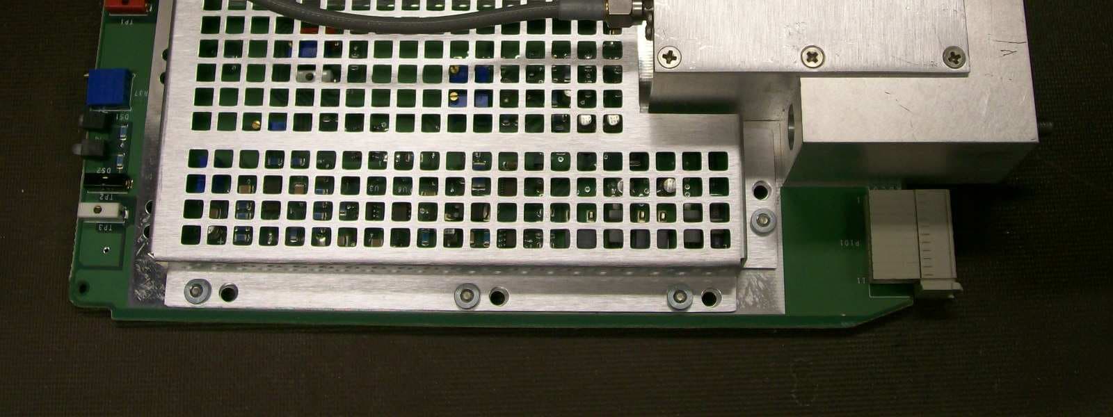
JF6-8702-50
Apr 26, 2010MDR-8000
Equipment Class
TNB - Licensed Non-Broadcast Station Transmitter
JF6-9558H
Jan 03, 2010MPT-HL Packet Terminal
Equipment Class
DTS - Digital Transmission System