JF69928RBLMDS Base Station Transceiver
Alcatel USA Marketing, Inc.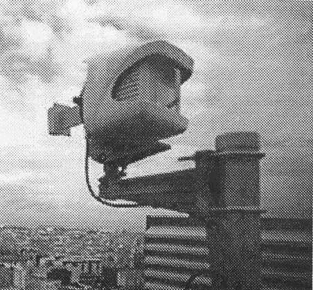
Click to zoom
Application Details
- Equipment Class
- TNB - Licensed Non-Broadcast Station Transmitter
- Date of Grant
- Mar 28, 2000
- Application Purpose
- Original Equipment
- Date of Application
- Jan 18, 2000
- Equipment Note
- LMDS Base Station Transceiver
- Frequency Range
- 28020.00000000 - 28335.00000000
- Company
- Alcatel USA Marketing, Inc.
- Country
- United States
Documents & Files
Document Text
Text extracted from the exhibit documents filed with the FCC. Open a document above to read the original.
Users Manual
document, use and communication of its contents not permitted without written authorization from ALCATEL All rights reserved. Passing on and copying of this Issue 02 -January, 10 20001/1363CC10875AAAA TQ BJA 02 ÄÄÄÄÄÄÄÄÄÄÄÄÄÄÄ ÄÄÄÄÄÄÄÄÄÄÄÄÄÄÄ ÄÄÄÄÄÄÄÄÄÄÄÄÄÄÄ ÄÄÄÄÄÄÄÄÄÄÄÄÄÄÄ ÄÄÄÄÄÄÄÄÄÄÄÄÄÄÄ Alcatel 9900 Multiservice broadband wireless access solution Base Station – release 2.0 USER MANUAL document, use and communication of its contents not permitted without written authorization from ALCATEL All rights reserved. Passing on and copying of this 2/1363CC10875AAAA TQ BJA 02 Issue 02 -January, 10 2000 PAGE INTENTIONALLY LEFT BLANK document, use and communication of its contents not permitted without written authorization from ALCATEL All rights reserved. Passing on and copying of this Issue 02 -January, 10 20003/1363CC10875AAAA TQ BJA 02 Table of contents 1 – Foreword7. . . . . . . . . . . . . . . . . . . . . . . . . . . . . . . . . . . . . . . . . . . . . . . . . . . . . . . . . . . . . . . . . . . . . . . . . . 1.1 – Structure of the manual7. . . . . . . . . . . . . . . . . . . . . . . . . . . . . . . . . . . . . . . . . . . . . . . . . . . . . . . . . 1.2 – Using the manual7. . . . . . . . . . . . . . . . . . . . . . . . . . . . . . . . . . . . . . . . . . . . . . . . . . . . . . . . . . . . . . 1.3 – Safety instructions8. . . . . . . . . . . . . . . . . . . . . . . . . . . . . . . . . . . . . . . . . . . . . . . . . . . . . . . . . . . . . 1.3.1 – General rules8. . . . . . . . . . . . . . . . . . . . . . . . . . . . . . . . . . . . . . . . . . . . . . . . . . . . . . . . . . 1.3.2 – Symbols on products8. . . . . . . . . . . . . . . . . . . . . . . . . . . . . . . . . . . . . . . . . . . . . . . . . . . 1.3.3 – Symbols used in the document9. . . . . . . . . . . . . . . . . . . . . . . . . . . . . . . . . . . . . . . . . . . 2 – Equipment overview11. . . . . . . . . . . . . . . . . . . . . . . . . . . . . . . . . . . . . . . . . . . . . . . . . . . . . . . . . . . . . . . 2.1 – Overview of the A9900 system11. . . . . . . . . . . . . . . . . . . . . . . . . . . . . . . . . . . . . . . . . . . . . . . . . . . 2.2 – Composition of the A9900 system12. . . . . . . . . . . . . . . . . . . . . . . . . . . . . . . . . . . . . . . . . . . . . . . . 2.3 – A9900 system specifications13. . . . . . . . . . . . . . . . . . . . . . . . . . . . . . . . . . . . . . . . . . . . . . . . . . . . . 2.3.1 – Frequency bands used13. . . . . . . . . . . . . . . . . . . . . . . . . . . . . . . . . . . . . . . . . . . . . . . . . . 2.3.2 – Radio transmission specifications13. . . . . . . . . . . . . . . . . . . . . . . . . . . . . . . . . . . . . . . . . 2.3.3 – Capacity14. . . . . . . . . . . . . . . . . . . . . . . . . . . . . . . . . . . . . . . . . . . . . . . . . . . . . . . . . . . . . . 2.4 – Simplified description of the Base Station (9900BS)16. . . . . . . . . . . . . . . . . . . . . . . . . . . . . . . . . 2.5 – Examples of configuration of the Base Station (9900BS)17. . . . . . . . . . . . . . . . . . . . . . . . . . . . 2.6 – Technical specifications of the Base Station (9900BS)18. . . . . . . . . . . . . . . . . . . . . . . . . . . . . . . 2.6.1 – RBS specifications18. . . . . . . . . . . . . . . . . . . . . . . . . . . . . . . . . . . . . . . . . . . . . . . . . . . . . 2.6.2 – DBS specifications18. . . . . . . . . . . . . . . . . . . . . . . . . . . . . . . . . . . . . . . . . . . . . . . . . . . . . 2.6.3 – Common characteristics of the RBS and DBS20. . . . . . . . . . . . . . . . . . . . . . . . . . . . . . 2.7 – Equipment power consumption21. . . . . . . . . . . . . . . . . . . . . . . . . . . . . . . . . . . . . . . . . . . . . . . . . . 2.7.1 – RBS21. . . . . . . . . . . . . . . . . . . . . . . . . . . . . . . . . . . . . . . . . . . . . . . . . . . . . . . . . . . . . . . . . . 2.7.2 – DBS21. . . . . . . . . . . . . . . . . . . . . . . . . . . . . . . . . . . . . . . . . . . . . . . . . . . . . . . . . . . . . . . . . . 3 – Installation of the Base Station23. . . . . . . . . . . . . . . . . . . . . . . . . . . . . . . . . . . . . . . . . . . . . . . . . . . . . 3.1 – Equipment delivery23. . . . . . . . . . . . . . . . . . . . . . . . . . . . . . . . . . . . . . . . . . . . . . . . . . . . . . . . . . . . . 3.1.2 – Checking the delivered configuration26. . . . . . . . . . . . . . . . . . . . . . . . . . . . . . . . . . . . . . 3.2 – Labels on the equipment28. . . . . . . . . . . . . . . . . . . . . . . . . . . . . . . . . . . . . . . . . . . . . . . . . . . . . . . . 3.3 – Installing the equipment29. . . . . . . . . . . . . . . . . . . . . . . . . . . . . . . . . . . . . . . . . . . . . . . . . . . . . . . . . 3.3.1 – Information required for installation29. . . . . . . . . . . . . . . . . . . . . . . . . . . . . . . . . . . . . . . 3.3.2 – Precautions29. . . . . . . . . . . . . . . . . . . . . . . . . . . . . . . . . . . . . . . . . . . . . . . . . . . . . . . . . . . 3.3.3 – Tools required29. . . . . . . . . . . . . . . . . . . . . . . . . . . . . . . . . . . . . . . . . . . . . . . . . . . . . . . . . 3.4 – Installation of outdoor equipment30. . . . . . . . . . . . . . . . . . . . . . . . . . . . . . . . . . . . . . . . . . . . . . . . . 3.4.1 – Definition of assemblies31. . . . . . . . . . . . . . . . . . . . . . . . . . . . . . . . . . . . . . . . . . . . . . . . . 3.4.2 – Installation and orientation of the mechanical system34. . . . . . . . . . . . . . . . . . . . . . . . 3.4.3 – Installation of the RBS radio antenna35. . . . . . . . . . . . . . . . . . . . . . . . . . . . . . . . . . . . . . 3.4.4 – Installation of the RBS Radio Unit (ODU)35. . . . . . . . . . . . . . . . . . . . . . . . . . . . . . . . . . 3.4.5 – Antenna alignment36. . . . . . . . . . . . . . . . . . . . . . . . . . . . . . . . . . . . . . . . . . . . . . . . . . . . . 3.4.6 – Grounding of the outdoor equipment38. . . . . . . . . . . . . . . . . . . . . . . . . . . . . . . . . . . . . . 3.5 – Installation of the link betw…
Text truncated - open the document above for the full version.
Block Diagram
9928RB: Radio Base Station 9928RB: Radio Base Station 9928RB: Radio Base Station 9928RB: Radio Base Station ARCHITECTURE ARCHITECTURE ARCHITECTURE ARCHITECTURE OMU OMU OMU OMU board board board board Feedthrough Feedthrough Feedthrough Feedthrough board board board board PSU PSU PSU PSU Tx/Rx Tx/Rx Tx/Rx Tx/Rx RF synthesizer RF synthesizer RF synthesizer RF synthesizer X3 X3 X3 X3 Coupler Coupler Coupler Coupler Detector Detector Detector Detector Detector Detector Detector Detector Adaptor Adaptor Adaptor Adaptor Antenna Antenna Antenna Antenna port port port port HPA HPA HPA HPA bias control bias control bias control bias control TX mixer TX mixer TX mixer TX mixer RX mixer RX mixer RX mixer RX mixer Diplexer Diplexer Diplexer Diplexer N connector N connector N connector N connector to DBS to DBS to DBS to DBS Exhibit 1 9928RB: Radio Base Station 9928RB: Radio Base Station 9928RB: Radio Base Station 9928RB: Radio Base Station BLOCK DIAGRAM BLOCK DIAGRAM BLOCK DIAGRAM BLOCK DIAGRAM LO 3 LO 3 LO 3 LO 3 LO 2 LO 2 LO 2 LO 2 LO 4 LO 4 LO 4 LO 4 LO 1 LO 1 LO 1 LO 1 On - On - On - On - 395 - 465 MHz 395 - 465 MHz 395 - 465 MHz 395 - 465 MHz 840 ±150 MHz 840 ±150 MHz 840 ±150 MHz 840 ±150 MHz 380 MHz 380 MHz 380 MHz 380 MHz Outdoor Monitoring Unit Outdoor Monitoring Unit Outdoor Monitoring Unit Outdoor Monitoring Unit Power Supply Power Supply Power Supply Power Supply 130 MHz 130 MHz 130 MHz 130 MHz TX IF TX IF TX IF TX IF RX IF RX IF RX IF RX IF RF Transceiver RF Transceiver RF Transceiver RF Transceiver 1305 1375 MHz 1305 1375 MHz 1305 1375 MHz 1305 1375 MHz LO 1 = 26660-27010 MHz or LO 1 = 26660-27010 MHz or LO 1 = 26660-27010 MHz or LO 1 = 26660-27010 MHz or 27760-27910 MHz 27760-27910 MHz 27760-27910 MHz 27760-27910 MHz LO 2 = 910 MHz LO 2 = 910 MHz LO 2 = 910 MHz LO 2 = 910 MHz LO 3 = 560 MHz LO 3 = 560 MHz LO 3 = 560 MHz LO 3 = 560 MHz Exhibit 2 TDM8 Bus ATM Cell Bus ANT Board TNT Board (x4) AMD Board(x4) I, Q I, Q STM-1/OC-3, (UNI 4.0) 16 x E1/T1 OBC OBC OBC LIU Craft Terminal (Ethernet 10BaseT) Ethernet Bus(10Base2) RS422/I2C BurstDemod. IF interface (Tx 140MHz & Rx 380MHz) IBS Board(x4) A NT: ATM Network Termination TNT: Telephony Network TerminationA MD: Air Modulator/Demodulator I BS: IF Base Station L IU: Line Interface Unit OBC: On-Board ControllerP ower supply blocks are not shown 9928RB: Digital Base Station 9928RB: Digital Base Station 9928RB: Digital Base Station 9928RB: Digital Base Station ARCHITECTURE ARCHITECTURE ARCHITECTURE ARCHITECTURE Exhibit 3
Cover Letter(s)
Page 1 of 1 January 24, 2000 TO: Federal Communications Commission Office of Engineering Technology Laboratory FROM: Jeffrey L. Zwiebel SUBJECT: Correction to Form 731 for FCC ID JF69928RB Please change Item 10 on Form 731 for FCC ID JF69928RB (Confirmation number EA96536) to indicate that the equipment will be operated under FCC Rule Part 101 only. The equipment is only required to conform to FCC Rule Part 15 as an unintentional radiator and is not operated under this rule as part of the transmitter certification.
Cover Letter(s)
Page 1 of 1 March 20, 2000 TO: Federal Communications Commission Office of Engineering Technology Laboratory FROM: Jeffrey L. Zwiebel Systems Development Staff Engineer Wireless Access SUBJECT: Equipment Specification Changes for FCC ID JF69928RB Please make the following changes to Item 12 on Form 731 for FCC ID JF69928RB (Confirmation number EA96536): • Change the frequency range to indicate operation is from 28020 to 28335 MHz. This change is to reflect the range of allowed center frequencies of operation instead of the nominal frequency band. This change also limits the range of operation in order to meet the emission mask requirements for the 27500 to 28350 MHz LMDS block. • Remove the indication of operation in the 29100 to 29350 MHz frequency band. Operation in this band has been suspended. • Change the emission designator to 23M7D7W. This change reflects the measured occupied bandwidth of the signal instead of the nominal full-power bandwidth. This designator also indicates that the carrier is amplitude and angle modulated by multiple digital channels of data, telephony, and telemetry information.
Cover Letter(s)
Page 1 of 1 March 20, 2000 TO: Federal Communications Commission Office of Engineering Technology Laboratory FROM: Jeffrey L. Zwiebel Systems Development Staff Engineer Wireless Access SUBJECT: Request for Confidentiality for FCC ID JF69928RB The Alcatel 9928RB certification application (FCC ID JF69928RB, confirmation number EA96536) was initially submitted without documents that require confidentiality. A cover letter dated January 24, 2000 requested changes to Form 731 to indicate that confidentiality is not requested. Schematic diagrams for the 9928RB and associated equipment were submitted on March 20, 2000 as part of the application. These documents contain information that is company confidential, may contain information pursuant to non-disclosure agreements, and of value to competitors. This information is not normally released to the general public. Pursuant to 47 CFR Part 0.459, Alcatel requests that all documents that are marked confidential remain confidential after the grant of certification is made. Please disregard the previous confidentiality letter dated January 24, 2000 and change Form 731, item 8, to indicate that a request for confidentiality is included in the application.
External Photos
9928RB: Radio Base Station 9928RB: Radio Base Station 9928RB: Radio Base Station 9928RB: Radio Base Station External Photos External Photos External Photos External Photos Exhibit 1 - Front View 9928RB: Radio Base Station 9928RB: Radio Base Station 9928RB: Radio Base Station 9928RB: Radio Base Station External Photos External Photos External Photos External Photos Exhibit 2 - Rear View 9928RB: Digital Base Station 9928RB: Digital Base Station 9928RB: Digital Base Station 9928RB: Digital Base Station External Photos External Photos External Photos External Photos Exhibit 3
ID Label/Location Info
Exhibit 1 - Example of FCC ID Label 9928RB 9928RB 9928RB 9928RB : Radio Base Station : Radio Base Station : Radio Base Station : Radio Base Station FCC ID Label FCC ID Label FCC ID Label FCC ID Label FCC ID Label 9928RB 9928RB 9928RB 9928RB : Radio Base Station : Radio Base Station : Radio Base Station : Radio Base Station FCC ID Label FCC ID Label FCC ID Label FCC ID Label Exhibit 2 - Location of FCC ID Label
ID Label/Location Info
2/23/2000 Exhibit 1 - Examples of ID Labels 9928RB : Radio Base Station ID Labels * Inc hesFCC ID Labe l Equipme nt ID Label 2/23/2000 Equipment ID Label 9928RB : Radio Base Station Labels Exhibit 2 - Location of ID Labels FCC ID Label
Internal Photos
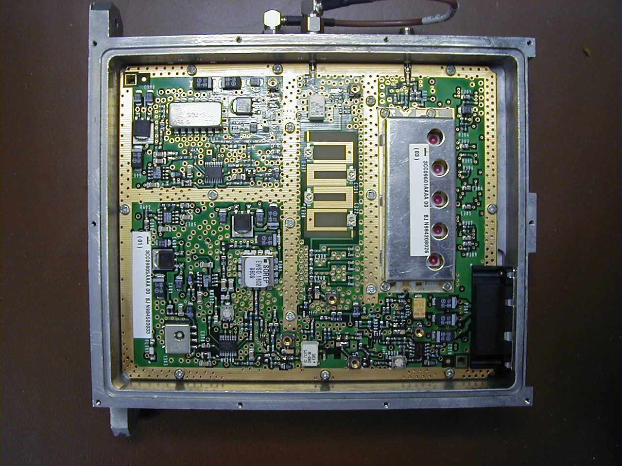
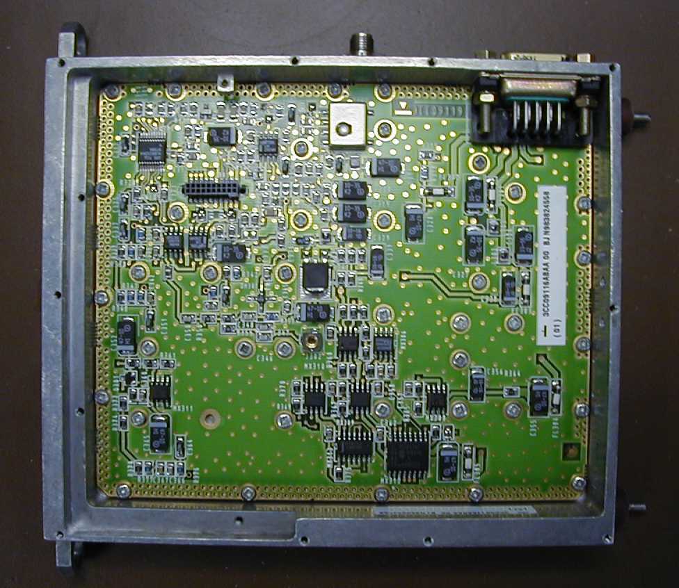
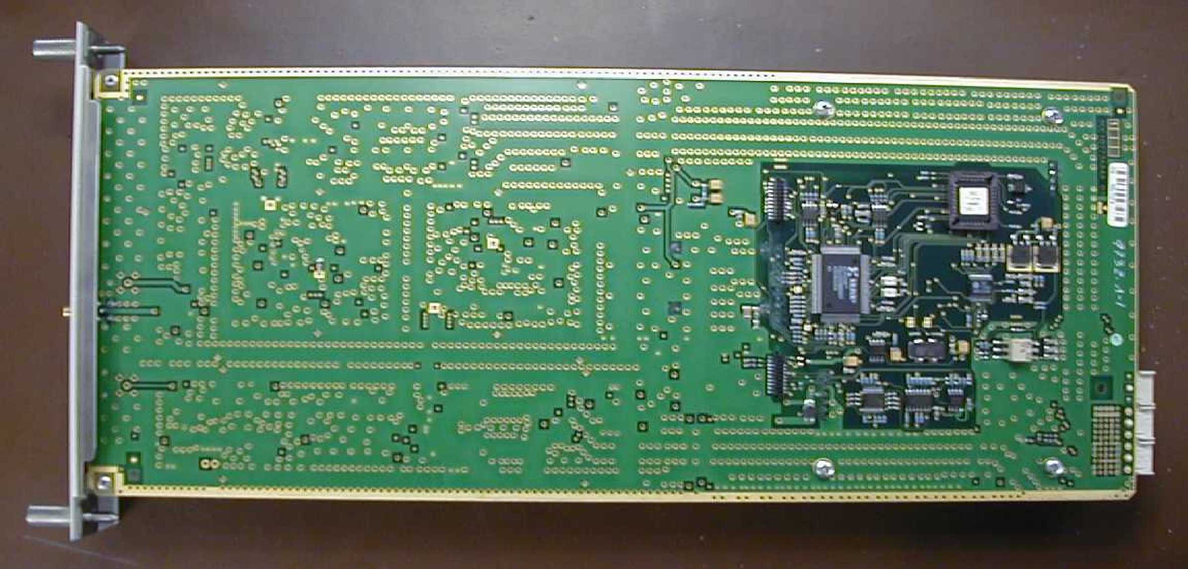
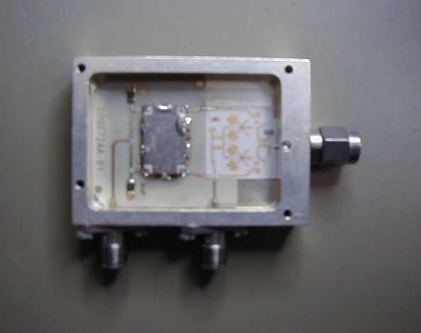
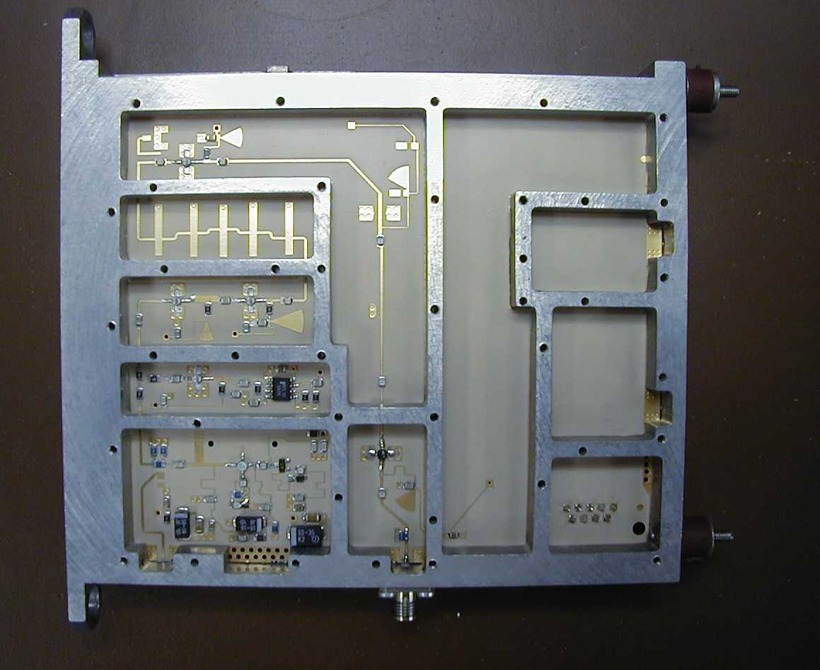
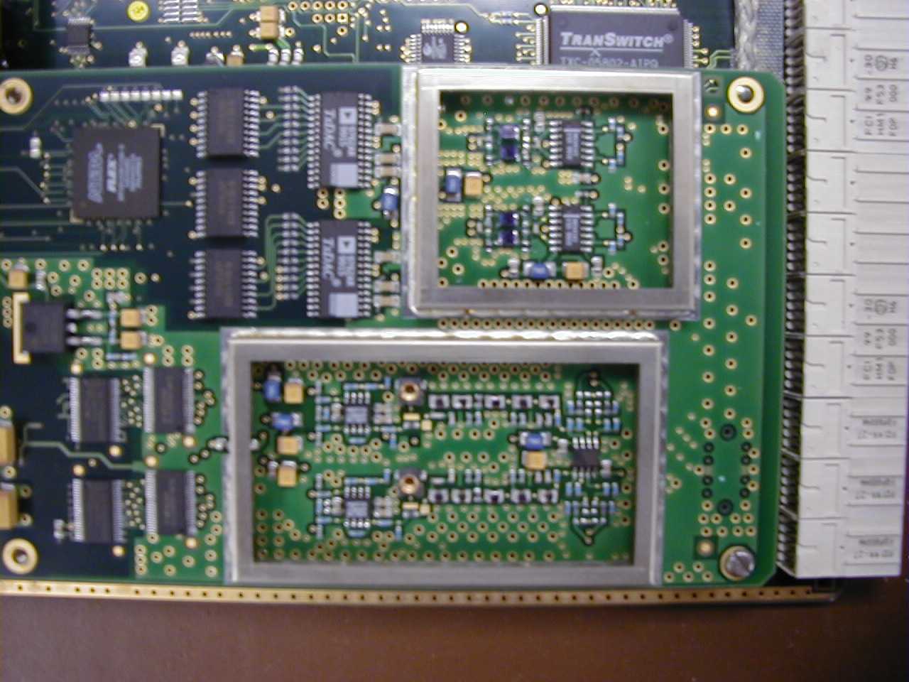
9928RB: Radio Base Station 9928RB: Radio Base Station 9928RB: Radio Base Station 9928RB: Radio Base Station Internal View Internal View Internal View Internal View Exhibit 1 - RBS Internal SYNTHESIZER SYNTHESIZER SYNTHESIZER SYNTHESIZER RF FRONT END RF FRONT END RF FRONT END RF FRONT END IF IF IF IF PSU PSU PSU PSU OMU board OMU board OMU board OMU board ( controller ) (co n t r o ll e r ) (co n t r o ll e r ) ( controller ) 9928RB: Radio Base Station 9928RB: Radio Base Station 9928RB: Radio Base Station 9928RB: Radio Base Station Internal View Internal View Internal View Internal View Exhibit 2 - RF Front End DIPLEXER DIPLEXER DIPLEXER DIPLEXER WR34 to WR28 taper WR34 to WR28 taper WR34 to WR28 taper WR34 to WR28 taper RX RF RX RF RX RF RX RF TX TX TX TX PA PA PA PA Bias control Bias control Bias control Bias control DAU DAU DAU DAU (TX level (TX level (TX level (TX level
Operational Description
04/27/011/3 FCC ID: 9900RB Operational Description Alcatel 9900 LMDS Base Station This is a summary of the operational description for the Alcatel 9900 LMDS Base Station transmitter as required for type certification under FCC Part 101. 04/27/012/3 System Overview The Alcatel 9900 is a Local Multipoint Distribution System (LMDS) that provides transport of packet data and telephony services between a central hub (base station) and multiple subscribers (terminal stations). The system operates in the 28000-28350 MHz and 29100-29250 MHz LMDS bands for downstream communications (hub to subscriber). The system operates in the 27500-28000 LMDS band for upstream communications (subscriber to hub). The base station is composed of two units, an indoor Digital Base Station (DBS) and an outdoor Radio Base Station (RBS). The DBS receives digital ATM and E1/T1 signals and modulates them to an IF TDM signal that is sent to the RBS. The RBS converts the IF signal to the downstream RF transmit frequency. The RBS receives burst TDMA signals from the terminal stations and converts them to IF receive signals. The DBS demodulates the IF signals and generates to digital data to be returned on the ATM and E1/T1 ports. Each RBS provides service for one quadrant of the LMDS cell. Each DBS provides support for up to four RBS transceivers for full cell coverage. The terminal station is also composed of two units, an indoor Network Termination (NT) and an outdoor Radio Termination (RT). The RT receives the RF signal from the base station and converts it to the receive IF frequency. The NT demodulates the IF signal and recovers the digital data to be provided to the subscriber interfaces. The NT also receives the digital data from the subscriber interfaces and modulates it into the transmit IF signal. This signal is only generated for specific time periods as authorized by the base station. The transmit IF signals are converted to the upstream RF frequency by the RT and transmitted as a narrow beam signal to the base station. Base Station Transmitter Description The DBS receives ATM packet data and E1/T1 telephony data and multiplexes it together into a TDM data stream. Reed-Solomon error correction is added to the TDM data. This data is then Viterbi and QPSK encoded and modulated to generate analog I/Q signals at 20.185 Mbaud. The I/Q modulator uses digital shaping filters with an α of 0.35. This results in a 27.25 MHz full power bandwidth signal. The I/Q signals are combined to generate a 130 MHz transmit IF signal. This signal is sent on a coaxial cable to the RBS along with 55 VDC for power and internal sub-carriers for RBS communication and control. The IF signal from the DBS is first amplified in the RBS using a programmable fixed gain stage to compensate for cable losses. It is then mixed to an IF frequency of 430 MHz. Filtering is used to remove unwanted sidebands and the signal is mixed to a second IF of 1340 MHz. This signal is amplified by a variable gain amplifier to maintain a programmed RF transmit level. This level is provisioned by the operator and has a 10 dB range. The IF signal is then filtered and mixed to the final RF transmit frequency. 04/27/013/3 All local oscillator frequencies are generated from programmable synthesizers that are phase locked to a 10 MHz TCXO reference. The frequencies are programmed by the DBS. An on-off control is provided to inhibit the transmit signal whenever any of the synthesizers are out-of-lock. The RF transmit signal is sent through a waveguide diplexer to the integral transmit antenna. This is a 90° sector antenna that has 15 dB of gain. Base Station Receiver Description The waveguide diplexer also directs the receive RF signals to the RBS receive circuits. The receive signals are amplified by an LNA and mixed to 840 MHz by the same LO as the final transmit stage. This IF is then filtered and mixed to 380 MHz. The IF signals are amplified by a programmable fixed gain amplifier to compensate for IF cable losses. The DBS receives the IF signals and recovers them using a burst TDMA demodulator. Up to four simultaneous signals may be received in each quadrant. Information about the receive signal level and frequency error is retained and used to signal the terminal stations for fine adjustment of their transmitter power and frequency. The digital data packets from the demodulator are buffered and routed as needed to the ATM and E1/T1 interface ports.
Test Report
922901/15 03/17/00 4:05 PM FCC ID: 9900RB Test Report Alcatel 9900 LMDS Base Station This is a summary of the test measurements performed on the Alcatel 9900 LMDS Base Station transmitter as required for type certification under FCC Part 101. Also included are measurements required for conformance with FCC Part 15 as a Class A unintentional radiator. 922902/15 03/17/00 4:05 PM Part 2.1045 - RF Power Output The Alcatel 9900 Base Station is made of two separate assemblies, an indoor Digital Base Station (DBS) and an outdoor Radio Base Station (RBS). The RBS uses internal circuitry to maintain a constant programmed transmitter output power. Losses generated in the cable between the RBS and the DBS are compensated for in the RBS. DC power for the RBS is supplied from the DBS through the connecting cable. Internal regulator circuits in the RBS generate the required bias currents and voltages for the transmitter devices. No operator adjustments are required other than to program the desired RBS output level. The RBS uses an integral 90° sector antenna. The transmitter power was measured with the antenna removed and a WR-28 to coaxial transition installed in its place. The transmitter power was then measured using an HP438A Power Meter with an HP8487A Power sensor. RBS part number:3CC10871AB Type design:solid state RBS DC Power:+55 VDC nominal 31 W nominal DC power Gain:10 to 31 dB Output Power:+7 to +17 dBm (nominal programmable output level) +16.5 dBm (measured output when programmed for maximum power) Antenna Gain:15 dB EIRP:1.4 W Test Setup: DBSRBS HP 438A P ower M eter HP 8487A Power Sensor +16.5 dBm 922903/15 03/17/00 4:05 PM Part 2.1047 - Modulation Characteristics The minimum attenuation limits for the modulated spectrum are defined in 101.111 (a)(2)(ii) by the following equation for frequencies removed from the center frequency by 50 to 250 percent of the authorized bandwidth: A = 11 + 0.4(P-50) + 10log(B). Maximum required attenuation is 56 dB. Measurements are to be made using a 1 MHz resolution bandwidth. The authorized bandwidth for the Base Station is the lower LMDS block from 27500 to 28350 MHz. This is an 850 MHz channel centered at 27295 MHz and translates into an attenuation mask defined by the following points: Frequency (MHz)Percent Attenuation (dB) 26862-25056 27160-9056 27500-5040 283505040 286909056 2898825056 Test Setup: DBSRBS FSEK20 Spectrum Analyzer 20 dB +16.5 dBm -10 dB m The RBS transmitter was set to its maximum nominal output and measured at the antenna output using the HP power meter as +16.5 dBm. The transmit spectrum was then measured with a Rhode&Schwarz FSEK20 spectrum analyzer using the power into the spectrum analyzer (including measurement cable losses) as the reference level. The Base Station operates on center frequencies between 28020 and 28335 MHz. The measurement results for each end of the operating range are shown in Exhibit 1 and Exhibit 2. Expanded measurements at the upper band edge are shown in Exhibit 3. The Base Station does not operate near the lower band edge. 922904/15 03/17/00 4:05 PM Exhibit 1 - Modulation Characteristics at 28020 MHz 922905/15 03/17/00 4:05 PM Exhibit 2 - Modulation Characteristics at 28335 MHz 922906/15 03/17/00 4:05 PM Exhibit 3 - Expanded Modulation Characteristics at 28335 MHz 922907/15 03/17/00 4:05 PM Part 2.1049 - Occupied Bandwidth The FSEK20 Spectrum Ana lyzer has the capability to calculate occupied bandwidth from a measured spectrum. The analyzer was set up to measure 99% bandwidth, resulting in the measurement of 23.63 MHz as shown in Exhibit 4. Exhibit 4 - Occupied Bandwidth 922908/15 03/17/00 4:05 PM Part 2.1051 - Emissions at the Antenna Port Emissions below 26862 MHz and above 28988 MHz are required by Part 101.111 (a)(2)(iii) to be attenuated from the transmitter output power by 43 + 10log(Power in watts) decibels. For a +17 dBm transmit power, this results in an attenuation of 30 dB. The RBS transmitter was set to its maximum nominal output and measured at the antenna output using the HP power meter as +16.5 dBm. The transmit spectrum was then measured with a Rhode&Schwarz FSEK20 spectrum analyzer using the power into the spectrum analyzer (including measurement cable losses) as the reference level. Measurements are to be made using a 4 kHz resolution bandwidth. Since this is not a standard spectrum analyzer bandwidth, a resolution bandwidth of 3 kHz was used with the reference level offset by -1 dB. Measurement results are shown in Exhibit 5. No significant spurious signals were found. 922909/15 03/17/00 4:05 PM Exhibit 5 - Emissions at the Antenna Port 9229010/15 03/17/00 4:05 PM Part 2.1053/15.109 - Field Strength of Spurious Radiation Measurements for spurious radiation were taken as part of the CISPR testing performed by CETECOM ICT Services. These results are shown in Exhibit 6, Exhibit 7, and Exhibit 8. Exhibit 6 - Spurious Radiation (horizontal) 9229011/15 03/17/00 4:05 PM Exhibit 7 - Spurious Radiation (vertical) 9229012/15 03/17/00 4:05 PM Exhibit 8 - Spurious Radiation (circular) 9229013/15 03/17/00 4:05 PM Part 2.1055 - Frequency Stability The RBS uses an ovenized crystal controlled oscillator to synthesize the frequencies required for IF/RF conversion. The RBS local oscillator frequency has a +/-8 ppm stability when operated over a temperature range of -33 ° to +55 ° C. The test unit transmit frequency was measured using the Rhode&Schwarz FSEK20 spectrum analyzer (equipped with a high stability time base that provides a measurement accuracy specified to be better than 0.1 ppm). The frequency was measured by monitoring the residual LO signal with the modulation removed. The results are shown in Exhibit 9. The base station transmitter is turned off whenever the RBS loses communication with the DBS or when the frequency synthesizers are out-of-lock. This prevents the base station from transmitting at the wrong frequency. 0.0 1.0 2.0 3.0 4.0 5.0 6.0 7.0 8.0 9.0 10.0 -30 -20 -10 0 10 20 30 40 5…
Text truncated - open the document above for the full version.
Test Report
933091/14 03/27/00 8:11 AM FCC ID: 9900RB Test Report Alcatel 9900 LMDS Base Station This is a summary of the test measurements performed on the Alcatel 9900 LMDS Base Station transmitter as required for type certification under FCC Part 101. Also included are measurements required for conformance with FCC Part 15 as a Class A unintentional radiator. 933092/14 03/27/00 8:11 AM Part 2.1045 - RF Power Output The Alcatel 9900 Base Station is made of two separate assemblies, an indoor Digital Base Station (DBS) and an outdoor Radio Base Station (RBS). The RBS uses internal circuitry to maintain a constant programmed transmitter output power. Losses generated in the cable between the RBS and the DBS are compensated for in the RBS. DC power for the RBS is supplied from the DBS through the connecting cable. Internal regulator circuits in the RBS generate the required bias currents and voltages for the transmitter devices. No operator adjustments are required other than to program the desired RBS output level. The RBS uses an integral 90° sector antenna. The transmitter power was measured with the antenna removed and a WR-28 to coaxial transition installed in its place. The transmitter power was then measured using an HP438A Power Meter with an HP8487A Power sensor. RBS part number:3CC10871AB Type design:solid state RBS DC Power:+55 VDC nominal 31 W nominal DC power Gain:10 to 31 dB Output Power:+7 to +17 dBm (nominal programmable output level) +16.5 dBm (measured output when programmed for maximum power) Antenna Gain:15 dB EIRP:1.4 W Test Setup: DBSRBS HP 438A P ower M eter HP 8487A Power Sensor +16.5 dBm 933093/14 03/27/00 8:11 AM Part 2.1047 - Modulation Characteristics The minimum attenuation limits for the modulated spectrum are defined in 101.111 (a)(2)(ii) by the following equation for frequencies removed from the center frequency by 50 to 250 percent of the authorized bandwidth: A = 11 + 0.4(P-50) + 10log(B). Maximum required attenuation is 56 dB. Measurements are to be made using a 1 MHz resolution bandwidth. The authorized bandwidth for the Base Station is the lower LMDS block from 27500 to 28350 MHz. This is an 850 MHz channel centered at 27925 MHz and translates into an attenuation mask defined by the following points: Frequency (MHz)Percent Attenuation (dB) 25800-25056 27167-89.356 27500-5040.3 283505040.3 2868389.356 3005025056 Test Setup: DBSRBS FSEK20 Spectrum Analyzer 20 dB +16.5 dBm -10 dB m The RBS transmitter was set to its maximum nominal output and measured at the antenna output using the HP power meter as +16.5 dBm. The transmit spectrum was then measured with a Rhode&Schwarz FSEK20 spectrum analyzer using the power into the spectrum analyzer (including measurement cable losses) as the reference level. The Base Station operates on center frequencies between 28020 and 28335 MHz. The measurement results for the high end of the operating range are shown in Exhibit 1 and Exhibit 2. The Base Station does not operate near the lower band edge of 27500 MHz. 933094/14 03/27/00 8:11 AM Exhibit 1 - Modulation Characteristics at 28335 MHz 933095/14 03/27/00 8:11 AM Exhibit 2 - Expanded Modulation Characteristics at 28335 MHz 933096/14 03/27/00 8:11 AM Part 2.1049 - Occupied Bandwidth The FSEK20 Spectrum Ana lyzer has the capability to calculate occupied bandwidth from a measured spectrum. The analyzer was set up to measure 99% bandwidth, resulting in the measurement of 23.63 MHz as shown in Exhibit 3. Exhibit 3 - Occupied Bandwidth 933097/14 03/27/00 8:11 AM Part 2.1051 - Emissions at the Antenna Port Emissions below 26862 MHz and above 28988 MHz are required by Part 101.111 (a)(2)(iii) to be attenuated from the transmitter output power by 43 + 10log(Power in watts) decibels. For a +17 dBm transmit power, this results in an attenuation of 30 dB. The RBS transmitter was set to its maximum nominal output and measured at the antenna output using the HP power meter as +16.5 dBm. The transmit spectrum was then measured with a Rhode&Schwarz FSEK20 spectrum analyzer using the power into the spectrum analyzer (including measurement cable losses) as the reference level. Measurements are to be made using a 4 kHz resolution bandwidth. Since this is not a standard spectrum analyzer bandwidth, a resolution bandwidth of 3 kHz was used with the reference level offset by -1 dB. Measurement results are shown in Exhibit 4. No significant spurious signals were found. 933098/14 03/27/00 8:11 AM Exhibit 4 - Emissions at the Antenna Port 933099/14 03/27/00 8:11 AM Part 2.1053/15.109 - Field Strength of Spurious Radiation Measurements for spurious radiation were taken as part of the CISPR testing performed by CETECOM ICT Services. These results are shown in Exhibit 5, Exhibit 6, and Exhibit 7. Exhibit 5 - Spurious Radiation (horizontal) 9330910/14 03/27/00 8:11 AM Exhibit 6 - Spurious Radiation (vertical) 9330911/14 03/27/00 8:11 AM Exhibit 7 - Spurious Radiation (circular) 9330912/14 03/27/00 8:11 AM Part 2.1055 - Frequency Stability The RBS uses an ovenized crystal controlled oscillator to synthesize the frequencies required for IF/RF conversion. The RBS local oscillator frequency has a +/-8 ppm stability when operated over a temperature range of -33 ° to +55 ° C. The test unit transmit frequency was measured using the Rhode&Schwarz FSEK20 spectrum analyzer (equipped with a high stability time base that provides a measurement accuracy specified to be better than 0.1 ppm). The frequency was measured by monitoring the residual LO signal with the modulation removed. The results are shown in Exhibit 8. The base station transmitter is turned off whenever the RBS loses communication with the DBS or when the frequency synthesizers are out-of-lock. This prevents the base station from transmitting at the wrong frequency. 0.0 1.0 2.0 3.0 4.0 5.0 6.0 7.0 8.0 9.0 10.0 -30 -20 -10 0 10 20 30 40 50 Temperature, deg C Frequency Error, ppm Exhibit 8 - RF Frequency Stability All frequency determining circuits are powered …
Text truncated - open the document above for the full version.
Test Setup Photos
9928RB: Radio Base Station 9928RB: Radio Base Station 9928RB: Radio Base S…
Text truncated - open the document above for the full version.
Contact Information
Applicant
Alfred Holland(R&D Manager)
Technical Contact
Alcatel Network Systems Inc.Jeffrey L Zwiebel
[email protected]972-996-7465
1225 N. Alma Road · Richardson, Texas · United States
Test Firm
Cetecom ICT Services GmbHRalf Hoehn
Technical Specifications
| # | Rule Parts | Frequency Range | Power Output | Emission | Tolerance |
|---|---|---|---|---|---|
| 1 | 101 | 28.02 GHz - 28.34 GHz | 50.00 mW | 23M7D7W | 8.0000000000 ppm |
Other Applications from Alcatel USA Marketing, Inc.
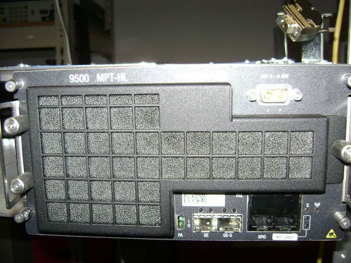
JF6-9558L-D
May 28, 20155 GHz rack-mounted point to point transceiver
Equipment Class
DTS - Digital Transmission System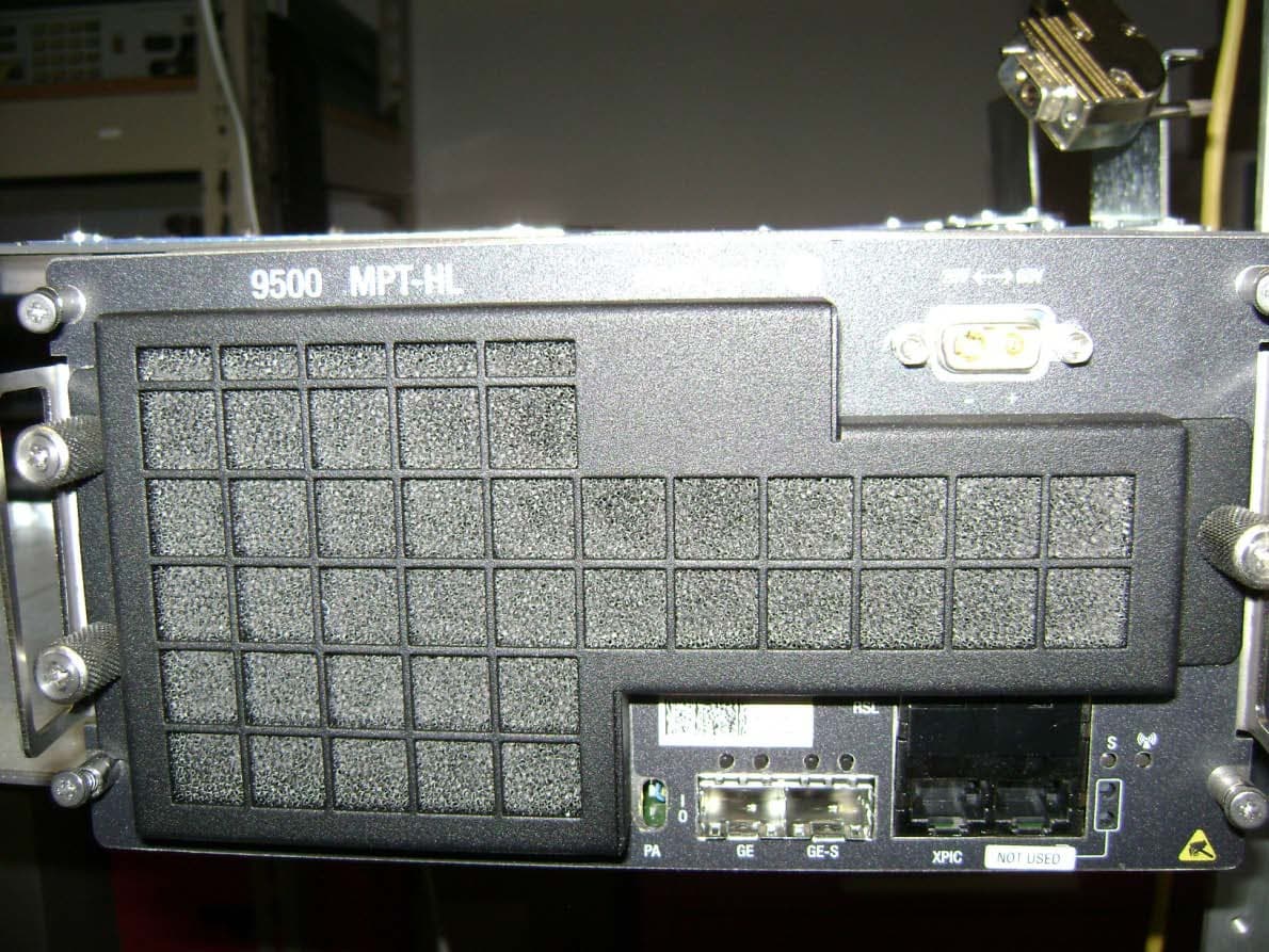
JF6-9558L
May 28, 20155 GHz rack-mounted point to point transceiver
Equipment Class
DTS - Digital Transmission System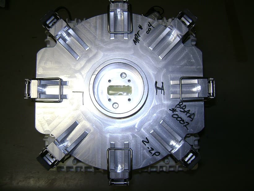
JF6-9558HC
Aug 06, 2012Microwave Packet Radio
Equipment Class
DTS - Digital Transmission System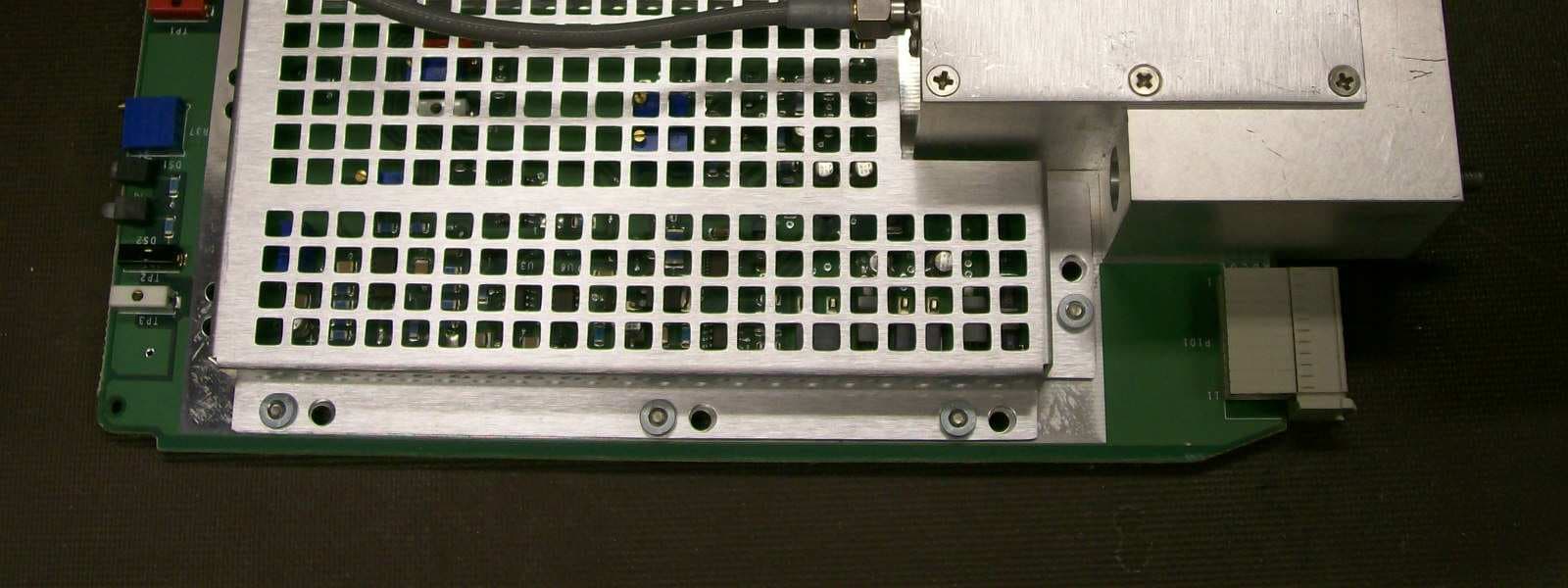
JF6-8702-50
Apr 26, 2010MDR-8000
Equipment Class
TNB - Licensed Non-Broadcast Station Transmitter
JF6-9558H
Jan 03, 2010MPT-HL Packet Terminal
Equipment Class
DTS - Digital Transmission System