JH5-70Level Radar
KROHNE, Inc
Click to zoom
Application Details
- Equipment Class
- DXX - Part 15 Low Power Communication Device Transmitter
- Date of Grant
- Apr 15, 2002
- Application Purpose
- Original Equipment
- Date of Application
- Apr 15, 2002
- Equipment Note
- Level Radar
- Frequency Range
- 8500.00000000 - 9500.00000000
- Company
- KROHNE, Inc
- Country
- United States
Documents & Files
Document Text
Text extracted from the exhibit documents filed with the FCC. Open a document above to read the original.
Users Manual
DIN A4: 7.02182.37.00 © KROHNE 11/2000US size: 7.02182.77.00 GR/LP Status: 05 -1998 Installation and operating instructions (Reference Manual) Level Radar BM 70 A / BM 70 P Non-contact level gauging using electromagnetic waves Variable area flowmeters Vortex flowmeters Flow controllers Electromagnetic flowmeters Ultrasonic flowmeters Mass flowmeters Level measuring instruments Communications engineering Engineering systems & solutions BM 70 A/P Montage- und BetriebsanleitungSeite: 211/00 Contents: General advice on safety................................3 Product liability and warranty .........................3 Items included with supply..............................3 Software history..............................................4 1. Range of application ................................6 2. Mode of operation and system structure.6 2.1 Operating principle ...................................6 2.2 Signal processing (digital).........................7 2.3 Modularity (signal converter, flange, antenna)....................................................7 3. Input...........................................................8 3.1 Measured variable (distance, level, volume, reflection) ....................................8 3.2 Measuring range [0.5-35/40 m (1.64-115/131 ft)] .....................................8 3.3 Block distance...........................................8 3.4 Out-of-range performance.........................8 4. Output........................................................9 4.1 Variants.....................................................9 4.2 Ex-e current output HART ® .................... 10 4.3 Ex-i current output HART ® (type of protection: Ex de [ia]) ................ 10 4.4 HART ® communication............................ 11 4.5 Current output (non-communicable) ....... 11 4.6 Digital interface RS 485 ......................... 11 4.7 Breakdown signal.................................... 13 4.8 Digital input............................................. 13 5. Measuring accuracy................................ 14 5.1 Reference conditions............................... 14 5.2 Error of measurement ............................ 14 5.3 Repeatability........................................... 15 5.4 Measured value resolution/hysteresis ..... 15 5.5 Transient recovery time .......................... 16 5.6 Turn-on drift / turn-on characteristics ...... 16 5.7 Long-term drift ....................................... 16 5.8 Effect of ambient temperature ................ 16 6. Operating conditions ............................. 17 6.1 Installation conditions ............................. 17 6.2 Ambient conditions.................................. 25 6.3 Product conditions................................... 26 6.4 Maintenance .......................................... 27 7. Design...................................................... 28 7.1 Models ..... ............................................. 28 7.2 Dimensions and weights ......................... 29 7.3 Replacement of the signal converter....... 30 7.4 Field assembly........................................ 30 7.5 Selection of antenna type and size.............. 31 7.6 Materials of construction......................... 32 7.7 Process connection................................. 32 7.8 Electrical connection............................... 33 7.9 Terminating resistor for the RS 485 interface..................................... 34 8. User interface..........................................35 8.1 Local display .........................................35 8.2 Function of the keys...............................36 8.3 Operator control concept........................37 8.4 Table fo settable functions (Version 3.00, 3.03, 4.02, 4.03) .............39 8.5 Configuration examples..........................42 8.6 Description of functions..........................44 8.7 Functional checks...................................55 8.8 Pointers and error messages during measurements.......................................56 8.9 Messages on start-up.............................58 8.10 Faults and symptoms during start-up and measurement .................................58 8.11 Calculation of the measured value .......61 8.12 User program PC-CAT for Windows .........................................62 9. Power supply ..........................................63 9.1 Options, technical data...........................63 9.2 Fuses ....................................................63 9.3 Changeover of operating voltage and replacement of fuses.............................63 9.4 Advice on safety.....................................64 10. Certificates and approvals....................66 10.1 Hazardous-duty approvals.....................66 10.2 Other approvals and certificates ...........66 10.3 Explosion proof acc. to ATEX ...............67 10.4 Radio approval .....................................68 10.5 CE manufacturer’s declaration...............69 11. Order information .................................70 12. External standards, codes and directives ..............................................71 13. Quality assurance.................................71 Annex Annex A: Technical Data ............................72 Annex B: Type code / nameplates...............74 Annex C: Spare parts .................................77 Annex D: Signed declaration to accompany a device returned to KROHNE....80 Annex E: Table on documentation of device configuration....................81 Annex F: Index............................................82 Installation and operating instructions BM 70 A/PPage: 311/00 General advice on safety: •To carry: the device will weigh between approx. 16 kg (35.5 lb) and 30 kg (66.1 lb) or more! To carry, use both hands to lift the device carefully by the converter housing. If necessary, use lifting gear. •Whenhandlingthe BM 70 A/P, avoid hard blows, jolts, impacts, etc. Product liability and warranty: The BM 70 A/P level gauge is designed solely for measu…
Text truncated - open the document above for the full version.
Users Manual
ADDENDUM TO LEVEL RADAR INSTALLATION AND OPERATION INSTRUCTIONS: 7.02182.77.00 Compliance with U.S.A. FCC Part 15 Rules (FCC ID JH5-70) and FCC Part 90 Rules (JH5BM70) The BM70A Level Radar complies with Part 15 of the FCC Rules when installed in totally enclosed metal tanks. A label is affixed to the instrument as shown below: ` When installing the metal, “horn” antenna versions with metal gaskets (all metal, metal-sheathed, or spiral-wound metal gaskets), only normal installation procedures should be observed. When installing a device with a “Wave-Stick” PTFE antenna or with a non- metallic gasket, the installation must include the shielding strip (item “C) and the strap retainer (item “S”) shown in Section “6.1.8 Ultimate installation on the tank “ on page 23. Also, the flange bolt holes, top and bottom, must be completely covered by the bolt heads and nuts which may require the use of flange bolts and flange nuts or appropriately-sized flat washers. The item referred to by the asterisk should read – “ * required for European radio approvals and United States FCC Part 15 approval for Wave-Stick version or FCC Part 15 approval when installed with non-metallic gaskets”. When installing the BM70A in other than totally enclosed metal tanks, a site- specific license under FCC Part 90 Rules must be obtained as Krohne’s FCC identifier - FCC ID JH5BM70. Contact Krohne for procedure to obtain license. Please note: changes or modifications not expressly approved by Krohne, could void the user’s authority to operate the equipment. FCC ID JH5-70 Krohne Level Radar When installed in totally enclosed metal tanks, this device complies with Part 15 of the FCC Rules. Operation is subject to the following two conditions: (1) This device may not cause harmful interference, and (2) this device must accept any interference received, including interference which may cause undesired operation.
Cover Letter(s)
Curtis-Straus LLC 527 Great Road Littleton, Massachusetts 01460 Tel: 978.486.8880 Fax: 978.486.8828 Web: www.curtis-straus.com e-mail: [email protected] Worldwide Regulatory Approvals Experts ® Federal Communications Commission 7435 Oakland Mills Road Columbia, MD 21046 Gentlemen: This letter is to comply with 47 CFR 0.457(d)(2) pertaining to confidential material. Krohne, Inc. requests that the following documents regarding this submission for FCC ID JH5-70 be kept confidential: 1. Schematic 2. Bill of Materials 3. Block Diagram 4. Circuit Description The material above contains technical data, which would customarily be guarded from competitors. We at Curtis-Straus LLC are acting as an Agent on behalf of Krohne, Inc. in requesting confidentiality with regards to the preceding documents. Sincerely, Michael Buchholz Senior EMC Manager Curtis-Straus LLC 527 Great Road Littleton, MA 01460
Cover Letter(s)
From: Robert J. Ungar To: '[email protected]' Cc: Terry Mahn Sent: Wednesday, April 10, 2002 4:34 PM Subject: BM70 As we discussed, this morning I spoke to both Julie Knapp, Deputy Chief of OET and, at his suggestion, Fred Thomas, the FCC's IRAC representative concerning the scope of the Part 15 restricted band waiver granted to Krohne for its BM70 and BM702 devices. The bottom line is that changes to these devices will still come under the waiver as long as: 1)testing shows variants of the BM70 devices to be within Part 15 limits and 2) variants of the BM702 operate in a manner consistent with the test data filed with the Krohne waiver request. Both devices can only be certificated under Part 15 for use in steel tanks. According to Barc Beahm the BM70A is just the lineal descendent of the BM70 with accumulated changes over the last ten years. It is essentially the same device which sweeps through the same restricted bands and which, as you know, still complies with the Part 15 technical standards. Please let me know if you have any questions.
External Photos
External Photos Model #: BM 70 A FCC ID: JH5-70 Model #: BM 70 A FCC ID: JH5-70 Model #: BM 70 A FCC ID: JH5-70 Model #: BM 70 A FCC ID: JH5-70 Model #: BM 70 A FCC ID: JH5-70 Model #: BM 70 A FCC ID: JH5-70 Model #: BM 70 A FCC ID: JH5-70 Model #: BM 70 A FCC ID: JH5-70
ID Label/Location Info
Label for BM 70A for FCC Part 15: Krohne FRN # 006-7986-64 FCC ID JH5-70 Krohne Level Radar When installed in totally enclosed metal tanks, this device complies with Part 15 of the FCC Rules. Operation is subject to the following two conditions: (1) This device may not cause harmful interference, and (2) this device must accept any interference received, including interference which may cause undesired operation. Label is rectangular, 7/8” H x 3 5/8” W, to be installed along the top circumference of the converter electronics housing. Label is fabricated of photo anodized aluminum with Scotch 468 High Performance Adhesive. Minimum character size is 8 pt..
Internal Photos
Internal Photos Model #: BM 70 A FCC ID: JH5-70 Model #: BM 70 A FCC ID: JH5-70 Model #: BM 70 A FCC ID: JH5-70 Model #: BM 70 A FCC ID: JH5-70 Model #: BM 70 A FCC ID: JH5-70 Model #: BM 70 A FCC ID: JH5-70 Model #: BM 70 A FCC ID: JH5-70 Model #: BM 70 A FCC ID: JH5-70
Test Report
MEASUREMENT/TECHNICAL REPORT Company: Krohne, Inc. FRN: 0006-7986-64 Model: BM 70 A FCC ID: JH5-70 Description: This is a report to support a request for an original grant of equipment authorization. Equipment Type: Radiolocation device Report prepared for: Krohne, Inc. 7 Dearborn Road Peabody, MA 01960 Phone: (978) 535-6060 Fax: (978) 535-1720 Report prepared by: Evan D. Gould Curtis-Straus LLC 527 Great Road Littleton, MA 01460 USA Phone: 978-486-8880 FAX: 978-486-8828 FCC Application for Krohne, Inc.••FCC ID: JH5-70 •• Report No. EB1249-1 5-Apr-02 ______________________________________________________________________ _____________________________ ________________________________ Curtis-Straus LLC •• 527 Great Road •• Littleton, MA •• TEL (978) 486-8880 •• FAX (978) 486-8828 page 2 of 19 Introduction This report is an application for Certification of a Transmitter operating pursuant to Part 15.209 of the FCC Rules, 47 CFR. The model number covered by this report is BM 70 A. This report is designed to demonstrate the compliance of this device with the requirements outlined in 47 CFR Part 15 using the methods outlined in 47 CFR Part 2. The BM 70 A, in its most general form, is an FCC Part 90 licensed device. This application is an attempt to gain certification as an unlicensed transmitter under Part 15 using a waiver for operation in the band 9-10GHz issued by the FCC to Krohne on October 26, 2001 (included). As per the conditions of the waiver, this application is only for those installations of the BM 70 A which are inside a steel tank. The BM 70 A Level-Radar level gauging system can be implemented in various different configurations, each consisting of a combination of certain options. The particular options considered in this application for certification are listed below: (those options used during testing are indicated with an asterisk) Power Supply: 1) 24V DC * 2) 115/230V AC * Antenna Type: 1) Wave-Stick * 2) 8” Horn (Type 4) 3) 6” Horn (Type 3) * 4) 4” Horn (Type 2) 5) 3” Horn (Type 1) Signal Output: 1) Ex-e current output HART® * 2) Ex-i current output HART® 3) Current output 4) RS 485 + current output * 5) PROFIBUS FMS/DP 6) PROFIBUS PA 7) Foundation Fieldbus (FF) * The following factors and assumptions were considered in producing a test plan which would conservatively cover the entire range of configurations: 1) It is unlikely that there would exist differences in emissions characteristics between... a) ...the two power supply options at frequencies above 1GHz. b) ...the seven signal output options at frequencies above 1GHz. c) ...the three antenna types at frequencies below 1GHz. 2) It has been determined that three of the seven signal output options would be representative of the entire group regarding emissions characteristics: Ex-e current output HART®, RS 485 + current output, and Foundation Fieldbus. The interface options do not impact the operation of the transmitter and the three samples chosen represent the most fully featured versions of the seven available variants. FCC Application for Krohne, Inc.••FCC ID: JH5-70 •• Report No. EB1249-1 5-Apr-02 ______________________________________________________________________ _____________________________ ________________________________ Curtis-Straus LLC •• 527 Great Road •• Littleton, MA •• TEL (978) 486-8880 •• FAX (978) 486-8828 page 3 of 19 3) With regards to the voltage variation measurements, (pursuant to 47 CFR 15.31(e)) it has been determined sufficient to test the DC power supply option only. This determination was based on the fact that the AC power option delivers 24VDC power to the same 24V DC module used in the DC only configuration. 4) The sample tank used for testing can accommodate only up to a 6” horn antenna. All horn antenna testing was performed using the 6” horn. As the horn size increases, so does the gain of the antenna. Since the output of the transmitter cannot be varied, the worst-case configuration would be with the 8” horn. To compensate for the use of the 6” horn during testing, an out of tank measurement was made with both the 6” and 8” horns. This allowed us to generate a correction factor to determine the compliance of the worst-case 8” horn configuration. The resultant test plan is shown below: 1) Determine a correction factor to be added to the emissions measurements taken at the fundamental operating frequency of the BM 70 A w/ 6” Horn, in order to represent the emissions at the fundamental operating frequency of a properly implemented BM 70 A w/ 8” Horn. Determine the correction factor by taking measurements at the fundamental operating frequency of both antennas operating in “open air” with identical (maximized) positions relative to the receiving antenna. 2) Perform radiated emissions scans from 1 to 40GHz of both the 6” Horn, and Wave-Stick antennas using either power option and any communication option. 3) Perform radiated emissions scans from 30MHz to 1GHz of the following three configurations: a) AC supply; Wave-Stick; Ex-e current output HART® b) DC supply; 6” Horn; Foundation Fieldbus c) DC supply; 6” Horn; RS 485 + current output 4) Perform six conducted emissions scans from 450kHz to 30MHz consisting of both the DC supply and AC supply each in conjunction with the three representative signal output alternatives. 5) Perform the voltage variation measurements with any configuration, which has DC as its power supply option. Calculation of Duty Cycle Correction Factor 47 CFR 15.35(c) provides for an alternative method of representing a measurement of an emission above 1000MHz. Under normal circumstances, measurements of emissions above 1000MHz are taken with an average detector. In cases where it is not possible to use an average detector, it is acceptable to use a peak detector, provided that a correction factor is determined which correlates a peak measurement and an average measurement by way of a duty cycle calculation. The worst-case duty cycle is given as the maximum percenta…
Text truncated - open the document above for the full version.
Test Setup Photos
Setup Photo
Contact Information
Applicant
Robert Senk
Test Firm
Curtis-Straus LLCJonathan Stewart
Technical Specifications
| # | Rule Parts | Frequency Range | Power Output |
|---|---|---|---|
| 1 | 15C | 8.50 GHz - 9.50 GHz | - |
Other Applications from KROHNE, Inc

JH5-FMCW2463
Mar 08, 2010Non-contact Radar (FMCW) Level Meter
Equipment Class
DXX - Part 15 Low Power Communication Device Transmitter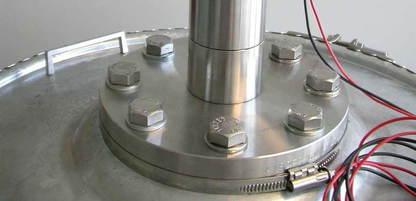
JH5OPTIWAVE7300CI
Oct 23, 2005Radar Level Meter
Equipment Class
DXX - Part 15 Low Power Communication Device Transmitter
JH5-OPTIWAVE7300C
Jul 29, 2004Radar Level Meter for operation within tanks
Equipment Class
DXX - Part 15 Low Power Communication Device Transmitter
JH5-702
Apr 17, 2002Level Radar
Equipment Class
DXX - Part 15 Low Power Communication Device Transmitter
JH5BM702
Oct 10, 2000Part 90.103 Fluid level sensor
Equipment Class
TNB - Licensed Non-Broadcast Station Transmitter