JH5-702Level Radar
KROHNE, Inc
Click to zoom
Application Details
- Equipment Class
- DXX - Part 15 Low Power Communication Device Transmitter
- Date of Grant
- Apr 17, 2002
- Application Purpose
- Original Equipment
- Date of Application
- Apr 17, 2002
- Equipment Note
- Level Radar
- Frequency Range
- 8500.00000000 - 9500.00000000
- Company
- KROHNE, Inc
- Country
- United States
Documents & Files
Document Text
Text extracted from the exhibit documents filed with the FCC. Open a document above to read the original.
Users Manual
© KROHNE 07/007.02230.31.00 Variable area flowmeters Vortex flowmeters Flow controllers Electromagnetic flowmeters Ultrasonic flowmeters Mass flowmeters Level measuring instruments Communications technology Engineering systems & solutions Installation and operating instructions Level-Radar BM 702 2 Installation and operating instructions BM 702 (07/00) Software History IntroductionSignal converterUser programInstructions Mth./YrHard- ware FirmwareHard- ware Operating system Soft- ware DeviceUser program 04/00BM 7027.00PREnnPCDOS 5.0 and higher PC-CAT 3.02 PRE01 05/007.02221.11+ Suppl. instruction Win95/98/NT PC-CAT Win 4.00 Online help Test versions for BM 702. 07/00BM 7027.00PCDOS 5.0 and higher PC-CAT 3.01 07/007.02221.11+ Suppl. instruction Win95/98/NT PC-CAT Win 4.00 Online help First series version for BM 702. Items included with supply The scope of supply includes, in the version as ordered: • Signal converter bolted to waveguide window and antenna; optionally: antenna extension, sunshade (with fastening material in each case) • Shielding material with tightening strap (not for the US market) • Installation and operating instructions plus instruction card • Report on factory settings for the signal converter • Certification and approval documents, unless reproduced in the device documentation Installation material (stud bolts, flange gasket and cabling) not supplied, to be provided by customer! 3 Installation and operating instructions BM 702 (07/00) Contents 1Handling and storage..................................................................................3 2Installation....................................................................................................4 2.1Field assembly..................................................................................................4 2.2Mechanical installation.....................................................................................5 3Electrical connection...................................................................................7 4Setting the parameters...............................................................................8 5Maintenance, error handling....................................................................18 6Safety information.....................................................................................19 7Technical data (extract)............................................................................20 8BM 702 Level-Radar Type code...............................................................22 9Parameter check list.................................................................................24 Product liability and warranty: The BM 702 level gauge is designed solely for measuring the level, distance, volume and reflection of liquids, pastes, slurries, particulate materials and solids. The BM 702 level gauge does not form part of an overfill protection system as defined in the WHG (= German water pollution regulation). Local codes and regulations apply to its use in hazardous areas. Responsibility as to suitability and intended use of these level gauges rests solely with the user. Improper installation and operation of our level gauges may lead to loss of warranty. In addition, the "General conditions of sale", form the basis of the purchasing contract. If you need to return the level gauge to the manufacturer or supplier, please refer to the information given in Section 5 i 1 Handling and storage Safety advice Depending on the version, the device will weigh between approx. 5 kg and 30 kg. To carry, use both hands to lift the device carefully by the converter housing. If necessary, use lifting gear. When handling the BM 702, avoid hard blows, jolts, impact, etc. When storing the "Wave-Stick" version, make sure that the device is not placed on its side on the PTFE antenna, as this may cause the rod to bend. 4 Installation and operating instructions BM 702 (07/00) 2 Installation Most of the BM 702 versions are supplied in fully assembled condition. In this case, you may skip this chapter. However, if a device should be delivered in parts, or parts are subsequently replaced, the following should be noted. 2.1 Field assembly • For any necessary field assembly of the BM 702, all parts are included with the supply (stud bolts, washers, etc.). • Bolt the waveguide window (flange mount) or distance piece, if supplied loose, to the BM 702. Torque for the sets of 4 Allen screws M (key size 5 mm): max. 8 Nm ∼ 0.8 kpm (5.8 ft lbf). • Note: Ensure the upper Teflon plug is kept absolutely dry and clean! Moisture and dirt will impair functionability of the BM 702! • Bolt antenna extension to the antenna; torque for the 3 stud bolts A: max. 8 Nm ∼ 0,8 kpm (5.8 ft lbf). Do not detach bolts H ! distance piece (for high-temperature version up to 250°C (482 °F) upper Teflon plug O-ring lower Teflon plug O-ring BM70 A connecting flange antenna extension antenna M H M A signal converter Version: Flange Stickplating (for Hastelloy, Stick GasketGasket Horn antenna Separation (Metaglass) Wave-StickWave-Stick (PP or PTFE) Flange system 96 with horn antenna LP flange system max. 2 bar max. 2 bar distance piece (optional) High temperature plate Horn antenna Flange Ti, Ta) PTFE w/o plate with horn antenna BM 702 converter 5 Installation and operating instructions BM 702 (07/00) 2.2 Mechanical installation Hazardous-duty systems: • The BM 702 Ex is certified in conformity with European Standard for use in Zone 0, 1 and 2 hazardous locations (dependent on version). • Attention is drawn to the data and information given on the nameplate of the converter, the nameplate of the flange and the specifications in the approval certificates. Safety: • Check material compatibility of antenna, extension, flange, gaskets, and PP or PTFE (used in all versions) with the product! See also section 8 "Type code"! Mounting on the tank nozzle a) Devices with horn antenna: The antenna should project out of the nozzle. …
Text truncated - open the document above for the full version.
Users Manual
ADDENDUM TO LEVEL RADAR INSTALLATION AND OPERATION INSTRUCTIONS: 7.02230.31.00 Compliance with U.S.A. FCC Part 15 Rules (FCC ID JH5-702) and FCC Part 90 Rules (JH5BM702) The BM702 Level Radar complies with Part 15 of the FCC Rules when installed in totally enclosed metal tanks. A label is affixed to the instrument as shown below: ` When installing the metal, “horn” antenna versions with metal gaskets (all metal, metal-sheathed, or spiral-wound metal gaskets), only normal installation procedures should be observed. When installing a device with a “Wave-Stick” PTFE antenna or with a non- metallic gasket, the installation must include the shielding strip (item “C) and the strap retainer (item “S”) shown in Section 2.2 - “Installation on the tank “ on page 6. Also, the flange bolt holes, top and bottom, must be completely covered by the bolt heads and nuts which may require the use of flange bolts and flange nuts or appropriately-sized flat washers. The item referred to by the asterisk should read – “ * required for European radio approvals and United States FCC Part 15 approval for Wave-Stick version or FCC Part 15 approval when installed with non-metallic gaskets”. When installing the BM702 in other than totally enclosed metal tanks, a site- specific license under FCC Part 90 Rules must be obtained as Krohne’s FCC identifier - FCC ID JH5BM702. Contact Krohne for procedure to obtain license. Please note: changes or modifications not expressly approved by Krohne, could void the user’s authority to operate the equipment. FCC ID JH5-702 Krohne Level Radar When installed in totally enclosed metal tanks, this device complies with Part 15 of the FCC Rules. Operation is subject to the following two conditions: (1) This device may not cause harmful interference, and (2) this device must accept any interference received, including interference which may cause undesired operation.
Cover Letter(s)
Curtis-Straus LLC 527 Great Road Littleton, Massachusetts 01460 Tel: 978.486.8880 Fax: 978.486.8828 Web: www.curtis-straus.com e-mail: [email protected] Worldwide Regulatory Approvals Experts ® Federal Communications Commission 7435 Oakland Mills Road Columbia, MD 21046 Gentlemen: This letter is to comply with 47 CFR 0.457(d)(2) pertaining to confidential material. Krohne, Inc. requests that the following documents regarding this submission for FCC ID JH5-702 be kept confidential: 1. Schematic 2. Bill of Materials 3. Block Diagram 4. Circuit Description The material above contains technical data, which would customarily be guarded from competitors. We at Curtis-Straus LLC are acting as an Agent on behalf of Krohne, Inc. in requesting confidentiality with regards to the preceding documents. Sincerely, Michael Buchholz Senior EMC Manager Curtis-Straus LLC 527 Great Road Littleton, MA 01460
External Photos
External Photos Model #: BM 702 FCC ID: JH5-702 Model #: BM 702 FCC ID: JH5-702 Model #: BM 702 FCC ID: JH5-702
ID Label/Location Info
\ Label for BM 702 for FCC Part 15: Krohne FRN # 006-7986-64 Label is rectangular, 7/8” H x 3 5/8” W, to be installed along the left side of the converter electronics housing. Label is fabricated of photo anodized aluminum with Scotch 468 High Performance Adhesive. Minimum character size is 8 pt.. FCC ID JH5-702 Krohne Level Radar When installed in totally enclosed metal tanks, this device complies with Part 15 of the FCC Rules. Operation is subject to the following two conditions: (1) This device may not cause harmful interference, and (2) this device must accept any interference received, including interference which may cause undesired operation.
Test Report
MEASUREMENT/TECHNICAL REPORT Company: Krohne, Inc. FRN: 0006-7986-64 Model: BM 702 FCC ID: JH5-702 Description: This is a report to support a request for an original grant of equipment authorization. Equipment Type: Radiolocation device Report prepared for: Krohne, Inc. 7 Dearborn Road Peabody, MA 01960 Phone: (978) 535-6060 Fax: (978) 535-1720 Report prepared by: Evan D. Gould Curtis-Straus LLC 527 Great Road Littleton, MA 01460 USA Phone: 978-486-8880 FAX: 978-486-8828 FCC Application for Krohne, Inc.••FCC ID: JH5-702 •• Report No. EB1249-2 8-Apr-02 ______________________________________________________________________ _____________________________ ________________________________ Curtis-Straus LLC •• 527 Great Road •• Littleton, MA •• TEL (978) 486-8880 •• FAX (978) 486-8828 page 2 of 10 Introduction This report is an application for Certification of a Transmitter operating pursuant to Part 15.209 of the FCC Rules, 47 CFR. The model number covered by this report is BM 702. This report is designed to demonstrate the compliance of this device with the requirements outlined in 47 CFR Part 15 using the methods outlined in 47 CFR Part 2. The BM 702, in its most general form, is an FCC Part 90 licensed device. This application is an attempt to gain certification as an unlicensed transmitter under Part 15 using a waiver for operation in the band 9-10GHz issued by the FCC to Krohne on October 26, 2001 (included). As per the conditions of the waiver, this application is only for those installations of the BM 702 which are inside a steel tank. The BM 70 A Level-Radar level gauging system can be implemented with different antennas. The particular antenna considered in this application for certification is the 6” Horn. A list of the different antenna types follows: Antenna Type: 1) Wave-Stick 2) 8” Horn (Type 4) 3) 6” Horn (Type 3) 4) 4” Horn (Type 2) 5) 3” Horn (Type 1) The sample tank used for testing can accommodate only up to a 6” horn antenna. All horn antenna testing was performed using the 6” horn. As the horn size increases, so does the gain of the antenna. Since the output of the transmitter cannot be varied, the worst-case configuration would be with the 8” horn. To compensate for the use of the 6” horn during testing, an out of tank measurement was made with both the 6” and 8” horns. This allowed us to generate a correction factor to determine the compliance of the worst-case 8” horn configuration. FCC Application for Krohne, Inc.••FCC ID: JH5-702 •• Report No. EB1249-2 8-Apr-02 ______________________________________________________________________ _____________________________ ________________________________ Curtis-Straus LLC •• 527 Great Road •• Littleton, MA •• TEL (978) 486-8880 •• FAX (978) 486-8828 page 3 of 10 Statement of Conformity The Krohne, Inc. BM 702 has been found to conform to the following parts of the 47 CFR as detailed below: Part 2 Part 15 Comments 15.15(b) The product contains no user accessible controls that increase transmission power above allowable levels. 2.925 15.19 The label is shown in the label exhibit. 15.21 Information to the user is shown in the instruction manual exhibit. 15.27 A section in the installation manual details the use of special accessories that are required for compliance. 15.31(e) Details of the voltage regulation circuit have been included in the application. 15.205 The fundamental operating frequency range includes two restricted bands from 15.205. (9.0-9.2GHz and 9.3-9.5GHz) Krohne has been granted a waiver by the FCC, which is included with this application. 15.209 All other emissions comply with the general emission limits of 15.209. 15.207 The unit complies with the conducted limits of 15.207. FCC Application for Krohne, Inc.••FCC ID: JH5-702 •• Report No. EB1249-2 8-Apr-02 ______________________________________________________________________ _____________________________ ________________________________ Curtis-Straus LLC •• 527 Great Road •• Littleton, MA •• TEL (978) 486-8880 •• FAX (978) 486-8828 page 4 of 10 Test Methodology Radiated emission testing was performed according to the procedures in ANSI C63.4 (1992). The testing was performed at an antenna to EUT distance of 3 meters below 1GHz, and at a distance of 0.1 meter above 1GHz. The test distance used is noted in the test data sheets. The device’s performance was investigated to 40GHz. The emissions were maximized around the vertical axis and the maximum reading was recorded. The antenna cannot be maximized separately. All other performance tests were made in accordance with the procedures outlined in 47 CFR Part 15. The applicable sections provided under Part 15 are provided in the measurement section of this report. FCC Application for Krohne, Inc.••FCC ID: JH5-702 •• Report No. EB1249-2 8-Apr-02 ______________________________________________________________________ _____________________________ ________________________________ Curtis-Straus LLC •• 527 Great Road •• Littleton, MA •• TEL (978) 486-8880 •• FAX (978) 486-8828 page 5 of 10 Test Facility Curtis-Straus LLC All radiated emissions testing in the range 30–40,000MHz was performed at Curtis-Straus (A2LA Certificate Number 1627-01). The open area test site used to collect the radiated data is located at 527 Great Road, Littleton, MA 01460. Site “M” was used. Test Equipment Used SPECTRUM ANALYZERS x Analyzer Model No. Company Serial No. Calibration Due X WHITE 9kHz-22GHz 8593E HP 3547U01252 25-JAN-2003 X GREEN 9kHz-26.5GHz 8593E HP 3829A03618 04-OCT-2002 X ORANGE 9kHz-26.5GHz E4407B HP US39440975 18-MAY-2002 LISNS x LISN Model No. Company Serial No. Calibration Due X YELLOW-BLACK 10kHz-30MHz 8012-50-R-24-BNC Solar 984735 02-OCT-2002 OPEN AREA TEST SITES (OATS) x Site FCC Code IC Code VCCI Code Calibration Due X “M” Maine 93448 IC 2762-M R-904/ C-480 23-JUN-2002 ANTENNAS x Antenna Model No. Company Serial No. Calibration Due X GREEN-BLACK Bilog: 30MHz-2GHz CBL6112B Chase 2412 28-JUN-2002 X BLACK Horn: 1-18GHz 3115 EM…
Text truncated - open the document above for the full version.
Test Setup Photos
Setup Photo
Contact Information
Applicant
Robert Senk
Test Firm
Curtis-Straus LLCJonathan Stewart
Technical Specifications
| # | Rule Parts | Frequency Range | Power Output |
|---|---|---|---|
| 1 | 15C | 8.50 GHz - 9.50 GHz | - |
Other Applications from KROHNE, Inc

JH5-FMCW2463
Mar 08, 2010Non-contact Radar (FMCW) Level Meter
Equipment Class
DXX - Part 15 Low Power Communication Device Transmitter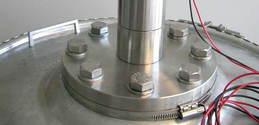
JH5OPTIWAVE7300CI
Oct 23, 2005Radar Level Meter
Equipment Class
DXX - Part 15 Low Power Communication Device Transmitter
JH5-OPTIWAVE7300C
Jul 29, 2004Radar Level Meter for operation within tanks
Equipment Class
DXX - Part 15 Low Power Communication Device Transmitter
JH5-70
Apr 15, 2002Level Radar
Equipment Class
DXX - Part 15 Low Power Communication Device Transmitter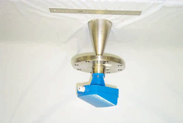
JH5BM702
Oct 10, 2000Part 90.103 Fluid level sensor
Equipment Class
TNB - Licensed Non-Broadcast Station Transmitter