JHICED1Remote Control
Graco Inc
Click to zoom
Application Details
- Equipment Class
- DSC - Part 15 Security/Remote Control Transmitter
- Date of Grant
- Apr 08, 2010
- Application Purpose
- Original Equipment
- Date of Application
- Feb 17, 2010
- Equipment Note
- Remote Control
- Frequency Range
- 433.92000000 - 433.92000000
- Company
- Graco Inc
- Country
- United States
Documents & Files
Document Text
Text extracted from the exhibit documents filed with the FCC. Open a document above to read the original.
Users Manual
Operation Drywall Feed Pump - For Water-Based Materials Only - Maximum Working Pressure 2500 psi (17.2 MPa, 172 bar) Model: 257100 Read all warnings and instructions 3A0245A ti14873a Warning 23A0245A Warning The following warnings are for the setup, use, grounding, maintenance, and repair of this equipment. The exclama- tion point symbol alerts you to a general warning and the hazard symbol refers to procedure-specific risk. Refer back to these warnings. Additional, product-specific warnings may be found throughout the body of this manual where applicable. WARNING FIRE AND EXPLOSION HAZARD Flammable fumes, such as solvent, in work area can ignite or explode. To help prevent fire and explo- sion: •Keep work area free of debris, including solvent, rags and gasoline. •Ground equipment in the work area. See Grounding instructions. •If there is static sparking or you feel a shock, stop spraying immediately. Do not use equipment until you identify and correct the problem. EQUIPMENT MISUSE HAZARD Misuse can cause death or serious injury. •Do not exceed the maximum working pressure or temperature rating of the lowest rated system component. See Technical Data in all equipment manuals. •Use water-based materials. Use fluids and solvents that are compatible with equipment wetted parts. SeeTechnical Data in all equipment manuals. Read fluid and solvent manufacturer’s warn- ings. •Check equipment daily. Repair or replace worn or damaged parts immediately. •Do not alter or modify equipment. •Use equipment only for its intended purpose. Call your Graco distributor for information. •Route hoses and cables away from traffic areas, sharp edges, moving parts, and hot surfaces. •Do not use hoses to pull equipment. •Keep children and animals away from work area. •Comply with all applicable safety regulations. PRESSURIZED EQUIPMENT HAZARD Fluid from the gun/dispense valve, leaks, or ruptured components can splash in the eyes or on skin and cause serious injury. •Follow Pressure Relief Procedure in this manual, when you stop spraying and before cleaning, checking, or servicing equipment. •Tighten all fluid connections before operating the equipment. •Check hoses, tubes, and couplings daily. Replace worn or damaged parts immediately. PERSONAL PROTECTIVE EQUIPMENT You must wear appropriate protective equipment when operating, servicing, or when in the operating area of the equipment to help protect you from serious injury, including eye injury, inhalation of toxic fumes, burns, and hearing loss. This equipment includes but is not limited to: •Protective eye wear •Clothing and respirator as recommended by the fluid and solvent manufacturer •Gloves •Hearing protection Warning 3A0245A3 MOVING PARTS HAZARD Moving parts can pinch or amputate fingers and other body parts. •Keep clear of moving parts. •Do not operate equipment with protective guards or covers removed. •Pressurized equipment can start without warning. Before checking, moving, or servicing equipment, follow the Pressure Relief Procedure in this manual. Disconnect power or air supply. WARNING Component Identification 43A0245A Component Identification 1Pump Module 2Prime/Tool Fill/Recirculation Valve 3Flow Knob 415/20 Amp Switch 5ON/OFF Switch 6Material Hoses 7Pump 8Pump Inlet Cover 9Hopper Plug 10Hopper 11Pump Connector 1 2 3 4 5 6 7 8 ti14874a 9 10 11 Finishing Tools 3A0245A5 Finishing Tools Corner Finisher 1. Press pin on top of corner finisher and install onto valve. 2. Work from bottom to top of vertical angles and from one end to other on ceiling angles. 3. Use drywall knife to detail corner and ceiling angle intersections. Flat Finishing Box 1. Install valve over two screws on box and tighten two wing nuts. 2. Place flat box at end of joint. 3. Lead with handle and draw the tool along the joint. 4. Near middle of the joint, remove flat box from joint surface with a sweeping motion. 5. Reverse hand positions and begin again at other end of joint. 6. Again draw flat box along joint up to previous stopping point and remove box from joint surface with a sweeping motion. 7. Use drywall knife to detail seams and overlap. Automatic Taping Tool NOTE: Fine flow rate adjustments can be made using buttons on valve handle. 1. Install trigger assembly and sanitary clamp. 2. Insert pin into trigger assembly. Pressure Relief Procedure 63A0245A 3. Insert cotter pin. 4. Place one hand on control tube and one hand at bottom of mud tub while in use. 5. Place tape at bottom of joint (slide tube forward to feed tape). 6. Lead with head of taper to make tracking easier. Large trigger feeds material through tool. Small trigger retracts creasing wheel. 7. Roll tape over seam with only one wheel in contact with wall until approximately three inches from end of seam. 8. Stop completely and pull tube back to cut tape. 9. Use drywall knife to detail seams and overlap. NOTE: Clean all tools thoroughly after every use. Use a brush and water to remove all joint compound from tools. Once tools have been cleaned, lightly oil using any light machine oil. Pressure Relief Procedure 1. Turn flow control knob OFF. 2. Point applicator into hopper and trigger to relieve pressure. 3. Fluid from pressure relief valve can splash in eyes or skin and cause serious injury. Keep hands clear of pressure relief valve. Wear safety glasses. Operation 3A0245A7 Operation FCC Notice (FCC ID: JHICED1) Model Number: DFS150 This device complies with Part 15 of the FCC rules. Operation is subject to the following two conditions: •This device may not cause harmful interference. •This device must accept any interference that may be received, including interference that may cause undesired operation. Changes or modifications not expressly approved by Graco, Inc. could void the user's authority to operate this equipment. IC Notice (IC: 4840ACED1) This product meets the applicable Industry Canada technical specifications/Le présent materiel est con- forme aux specifications techniques applicables d’Industrie C…
Text truncated - open the document above for the full version.
Cover Letter(s)
To: FCC Subject: Response to “Request for Administrative Info” Correspondence Reference Number: 38741 FCC ID: JHICED1 Date: 2010-04-07 1. Disregard earlier uploaded document “FCC Authorization for Resolution Engineering.pdf ”. Instead, please review the newly uploaded document “FCC Authorization for Resolution Engineering_2.pdf” that is signed by the contact listed in the 731 form. 2. Disregard earlier uploaded document “FCC Confidentiality Request Letter.pdf ”. Instead, please review the newly uploaded document “FCC Confidentiality Request Letter_2.pdf” that is signed by the contact listed in the 731 form. 3. Disregard earlier uploaded document “Exhibit A - Label.pdf ”. Instead, please review the newly uploaded document “Exhibit A - Label_2.pdf” that shows the label placement. Rob Hendrickson Resolution Engineering, Inc. Agent for Graco, Inc.
ID Label/Location Info
LABEL 293696C Connect to an Individual Branch Circuit. PSI / Bar / MPa SERIAL NO. SERIES PART NO. 2500 / 172.4 / 17.2 120 AC15 / 2060 HZAMPS VOLTS ̃ Graco Artwork Artwork Number: 293696 Revision: C Artwork Size: 1:1 Artwork Date: 2/2010 Project / ECO #: Z054517 Border is for reference only Color: All characters and border are black unless otherwise noted. GRACO INC. P.O. Box 1441 Minneapolis, MN 55440 FCC ID: JHICED1 IC: 4840ACED1 DFS150 MADE IN USA
Test Report
Frequency CE Regulations Transmit Power Limit CE Regulations Transmit Power Limit Power density 3 meters from a transmitter transmitting at the CE power limit Field strength 3 meters from a transmitter transmitting at the CE power limit Margin by which EUT passed CE test EUT field strength at 3 meters FCC 3 meter field strength limit Margin by which EUT passes FCC limit MHzdBmWattsWatts/m^2dBuV/mdBdBuV/mdBuV/mdB 433.920100.018.84194E-05105.228787525.879.43100.821.37 867.920-362.51189E-072.221E-0959.228787454.354.9380.825.87 1301.876-300.0000018.84194E-0965.228787458.756.537417.47 1735.826-300.0000018.84194E-0965.2287874548.816.4380.864.37 2169.782-300.0000018.84194E-0965.2287874548.416.8380.863.97 2603.738-300.0000018.84194E-0965.2287874549.216.0380.864.77 3037.695-300.0000018.84194E-0965.228787454619.2380.861.57 3471.651-300.0000018.84194E-0965.2287874543.321.9380.858.87 3905.608-300.0000018.84194E-0965.2287874546.318.937455.07 4339.564-300.0000018.84194E-0965.2287874544.620.637453.37 Permeability1.25664E-06 Newtons/amp^2 Speed of Light3.00E+08 m/s Measurements were taken using the substitution method with respect to CE limits so the below table calculates the FCC margin of passing based on the CE margin of passing.
Test Report
FCC Certification Test Report for FCC ID: JHICED1 Mfg: Graco, Inc. 20500 David Koch Ave Rogers, MN 55374 USA February 8, 2010 Contents 1. Introduction ...............................................................................................................................................................3 2. Statement of Compliance ...........................................................................................................................................3 2.1. FCC Part 2 §2.907 ..................................................................................................................................................3 2.2. FCC Part 2 §2.911 ..................................................................................................................................................3 2.3. FCC Part 2 §2.913 ..................................................................................................................................................3 2.4. FCC Part 2 §2.915 ..................................................................................................................................................3 2.5. FCC Part 2 §2.925 ..................................................................................................................................................3 2.6. FCC Part 2 §2.943, 2.945 .......................................................................................................................................3 2.7. FCC Part 2 §2.947 ..................................................................................................................................................3 2.8. FCC Part 2 §2.948 ..................................................................................................................................................4 2.9. FCC Part 2 §2.1033 ................................................................................................................................................5 3. Discussion of Laboratory Measurements and Rules Compliance ..............................................................................6 3.1. FCC Part 15 §15.231(a)(1) .....................................................................................................................................6 3.2. FCC Part 15 §15.231(a)(3) .....................................................................................................................................6 3.3. FCC Part 15 §15.231(a)(4) .....................................................................................................................................6 3.4. FCC Part 15 §15.231(a)(5) .....................................................................................................................................6 3.5. FCC Part 15 §15.231(b) .........................................................................................................................................6 3.5.1. Raw Field Strength Limits ...................................................................................................................................6 3.5.2. Duty Cycle Correction Factor and Resulting Limits ............................................................................................7 3.5.3. Measured Radiated Field Strength Data ..............................................................................................................7 3.6. FCC Part 15 §15.231(c)..........................................................................................................................................7 1. Introduction The JHICED1 is a transmitter used for controlling a sprayer. The unit is powered by a 3VDC battery. The transmitter is centered at 433.92MHz and is controlled by a SAW resonator. The device measures approximately 130 mm(L) x 60 mm(H) x 30 mm(W) and has mass approximately 100 grams. Certification is requested under FCC Rules, Part 15, Subpart C, Paragraph 15.231. 2. Statement of Compliance Specific sections of FCC Rules Part 2 that require information or listing are given below. 2.1. FCC Part 2 §2.907 This is an application for certification of original equipment 2.2. FCC Part 2 §2.911 a) This application has been filed electronically using form 731. b) All required information has been supplied in this application and its attachments. c) This applicant has signed the application electronically. d) The technical test data has been signed by the agency performing the testing. e) Signature supplied in appropriate block on form 731. f) Processing fee has been paid by credit card. g) Signatures have been supplied electronically. 2.3. FCC Part 2 §2.913 a) This application has been filed electronically. b) Appropriate fees have been filed electronically. c) Equipment samples shall be supplied as requested. 2.4. FCC Part 2 §2.915 We are requesting a grant of certification. This application shows compliance with the technical standards. 2.5. FCC Part 2 §2.925 A label shall be affixed to each piece of equipment, showing the FCC identifier. The label shall read “FCC ID: JHICED1”. See Exhibit A for a photograph showing the label and location on the back of the device. 2.6. FCC Part 2 §2.943, 2.945 Sample production equipment shall be submitted to the FCC upon request. 2.7. FCC Part 2 §2.947 a) Measurement procedure follows ANSI C63.4. b) A description of utilized test equipment is contained in the report. 2.8. FCC Part 2 §2.948 Radiated measurements were taken at the following FCC-approved facility: Rhein Tech Laboratories, Inc. 360 Herndon Pkwy, Suite 1400 Herndon, VA 20170 Contact: Rick McMurray Phone: 703-689-0368 A photograph of the test site is shown below: 2.9. FCC Part 2 §2.1033 a) Form 731 has been filed electronically. b) The technical report, along with its exhibits, contains the information as follows: (1) full name and mailing address of the manufacturer of the device and the applicant for certification: Graco Inc.…
Text truncated - open the document above for the full version.
Contact Information
Applicant
Kyle Somora(Product Safety and Compliance Engineer)
Test Firm
Rhein Tech Laboratories, Inc.Rick McMurray
Technical Specifications
| # | Rule Parts | Frequency Range | Power Output | Emission | Tolerance |
|---|---|---|---|---|---|
| 1 | 15.231 | 433.92 MHz - 433.92 MHz | 1.00 mW | A2D | 75000.0000000000 Hz |
Other Applications from Graco Inc

JHICED2
Jan 27, 202017U762
Equipment Class
DSC - Part 15 Security/Remote Control Transmitter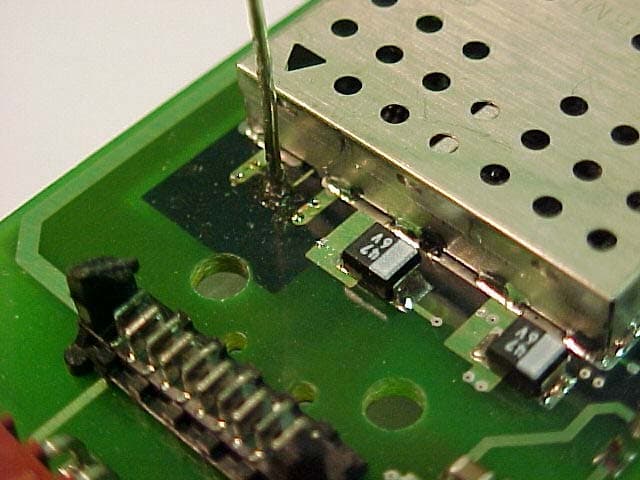
JHIGNET
Dec 05, 2005Transceiver Module
Equipment Class
DSS - Part 15 Spread Spectrum Transmitter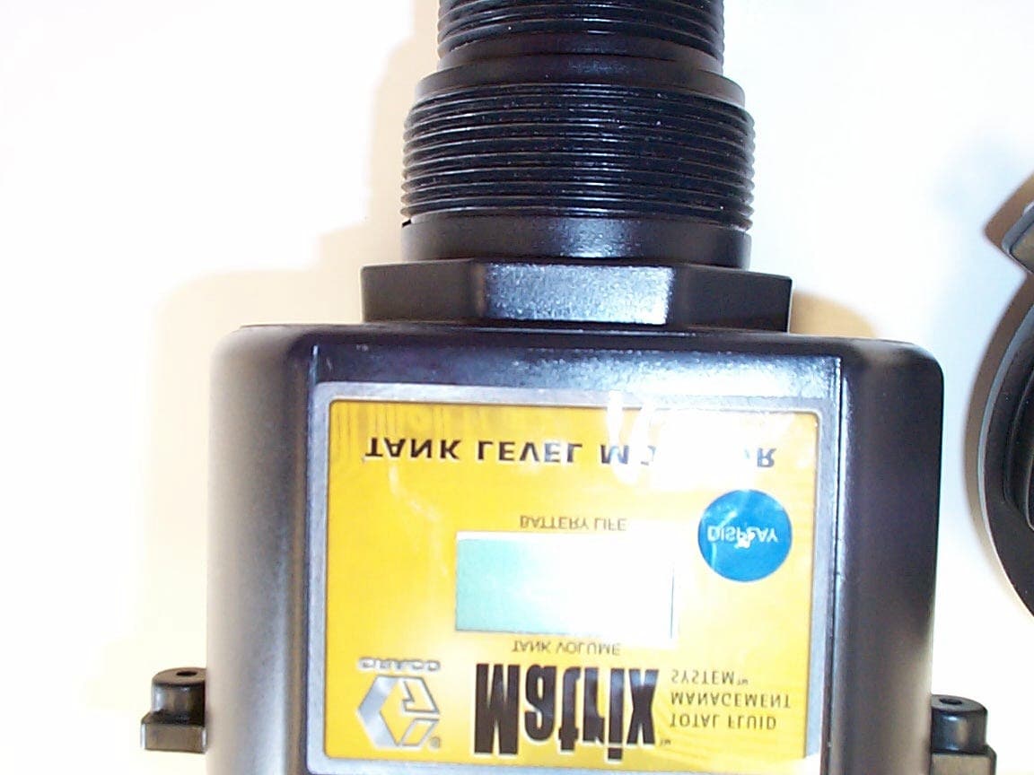
JHITANKTXRX
Sep 10, 2002Matrix Tank Level Monitor
Equipment Class
DXT - Part 15 Low Power Transceiver, Rx Verified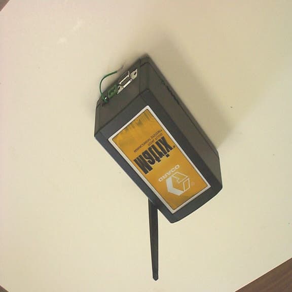
JHITXRX
Sep 09, 2002PC Transceiver or Repeater or Wall Buster
Equipment Class
DXT - Part 15 Low Power Transceiver, Rx Verified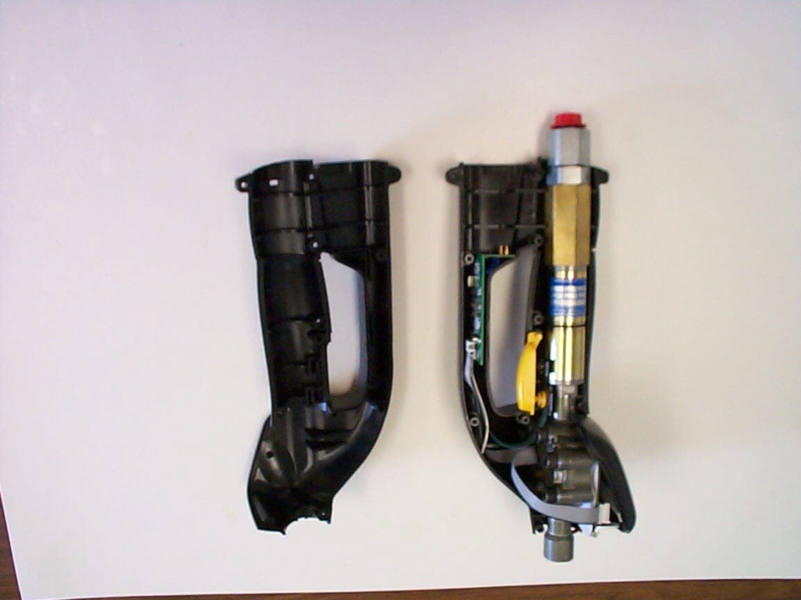
JHIMETERTXRX
Sep 09, 2002Matrix Meter
Equipment Class
DXT - Part 15 Low Power Transceiver, Rx Verified