JHIMETERTXRXMatrix Meter
Graco Inc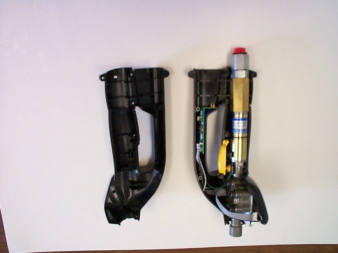
Click to zoom
Application Details
- Equipment Class
- DXT - Part 15 Low Power Transceiver, Rx Verified
- Date of Grant
- Sep 09, 2002
- Application Purpose
- Original Equipment
- Date of Application
- Jul 26, 2002
- Equipment Note
- Matrix Meter
- Frequency Range
- 915.00000000 - 915.00000000
- Company
- Graco Inc
- Country
- United States
Documents & Files
Document Text
Text extracted from the exhibit documents filed with the FCC. Open a document above to read the original.
External Photos
1100 Falcon Ave.Tele:320-864-4444 Glencoe, MN 55336Fax: 320-864-6611 “Your Agent to Product Certifications and Licenses Throughout the World” July 5, 2002 Graco Inc. & Subsidiaries Product: Matrix Meter P/N: 246008 EXTERNAL PHOTOS TOP VIEW: INTERNATIONAL CERTIFICATION SERVICES INC. International Certification Services, Inc. [email protected] SIDE VIEW: International Certification Services, Inc. [email protected] INTERNAL CONSTRUCTION:
ID Label/Location Info
1100 Falcon Ave.Tele:320-864-4444 Glencoe, MN 55336Fax: 320-864-6611 “Your Agent to Product Certifications and Licenses Throughout the World” July 5, 2002 Graco Inc. & Subsidiaries Product: Matrix Meter P/N: 246008 LOCATION OF THE FCC LABEL INTERNATIONAL CERTIFICATION SERVICES INC. FCC LABEL LOCATION International Certification Services, Inc. [email protected] FCC LABEL DRAWING: JHI METERTXRX
Internal Photos
1100 Falcon Ave.Tele:320-864-4444 Glencoe, MN 55336Fax: 320-864-6611 “Your Agent to Product Certifications and Licenses Throughout the World” July 5, 2002 Graco Inc. & Subsidiaries Product: Matrix Meter P/N: 246008 INTERNAL PHOTOS INTERNAL CONSTRUCTION VIEW: INTERNATIONAL CERTIFICATION SERVICES INC. Internal fixed Receive Antenna Display PC board assembly RF Transmitter PC assembly International Certification Services, Inc. [email protected] THREE PC BOARD ASSEMBLY LCD DISPLAY DISPLAY PC BOARD ASSEMBLY RF TRANSMITTER PC BOARD ASSEMBLY FIXED INTERNAL RECEIVING ANTENNA International Certification Services, Inc. [email protected] INTERNAL FIXED RECEIVING ANTENNA: INTERNAL FIXED RECEIVING ANTENNA International Certification Services, Inc. [email protected] TRANSMITTER ANTENNA (PC BOARD FOIL): TRANSMITTING ANTENNA FOIL
Test Report
TEST REPORT #280702 STANDARD: FCC PART 15 SUBPART C--INTENTIONAL RADIATORS SECTION 15.249 OPERATION WITHIN THE BANDS 902-928 MHZ, 2400-2483.5 MHZ, 5725-5875 MHZ, AND 24.0-24.25 GHZ. EQUIPMENT TESTED: GRACO INC. & SUBSIDIARIES MODEL: MATRIX METER P/N: 246008 TEST DATE: 28 JULY 2002 INTERNATIONAL CERTIFICATION SERVICES, INC. 1100 Falcon Avenue Glencoe, MN 55336 Tele: 320-864-4444 Fax: 320-864-6611 INTERNATIONAL CERTIFICATION SERVICES, INC. Prepared for: Test agent: Test location: Prepared by: . Graco Inc. & Subsidiaries PO Box 1441 Minneapolis, MN 55440-1441 International Certification Services, Inc. 1100 Falcon Avenue Glencoe, MN 55336 Tele: 320-864-4444 Fax: 320-864-6611 International Certification Services, Inc. 1100 Falcon Avenue Glencoe, MN 55336 Tele: 320-864-4444 Fax: 320-864-6611 International Certification Services, Inc. 1100 Falcon Avenue Glencoe, MN 55336 International Certification Services represents to the client that testing is done in accordance with standard procedures applicable and that reported test results are accurate within generally accepted commercial ranges of accuracy. This report only applies to the specific samples tested under stated test conditions. It is the manufacturer’s responsibility to assure that additional production units of this model are manufactured with identical electrical and mechanical components. International Certification Services shall have no liability for any deductions, inferences or generalizations drawn by the client or others from this report. This report is the confidential property of the client. As a mutual protection to our clients, the public and ourselves, extracts from the test report shall not be reproduced except in full without our written approval. INTERNATIONAL CERTIFICATION SERVICES, INC. 1.0 TEST SUMMARY TEST REPORT: #280702 COMPANY: AGENT:International Certification Services, Inc. PHONE:320-864-4444 TEST DATE: EQUIPMENT UNDER TEST: GENERAL TEST SUMMARY: VERIFICATION / CERTIFICATION STATUS: MODIFICATIONS NECESSARY: TESTED BYWRITTEN BY Duane R. BagdonsDuane R. Bagdons Graco Inc. & Subsidiaries 28 July, 2002 Matrix Meter, P/N: 246008 The testing was performed at International Certification Services, Inc. at 1100 Falcon Ave, Glencoe, MN 55336 The Matrix Meter, P/N: 246008 was found to be in compliance with the FCC Part 15 Subpart C, Section 15.249 requirements. None INTERNATIONAL CERTIFICATION SERVICES, INC. Applicable Standards 47 CFR Ch.1 (10-1-98 Edition) FCC Part 15Radio Frequency Devices Subpart CIntentional Radiators Section 15.249Operation within the Bands 902-928 Mhz, 2400- 2483.5 Mhz, 5725-5875 Mhz, and 24.0-24.25 Ghz 2.1Referenced Standards ANSI C63.4-1992Methods of Measurement of Radio-Noise Emissions from Low- Voltage Electrical and Electronic Equipment in the Range of 9 Khz to 40 Ghz. 2.2 Equipment Units Tested The equipment tested is a Handheld meter for dispensing liquids and monitoring the that was dispensed. The Receiver portion of the circuit is an integrated chip (Melixis TH71112 (868-915 Mhz FSK/FMIASK Receiver) which is preceded by a SAW filter. The Transmitter portion of the circuit is also a Melxis chip Type (TH71081 868-915 ASK Transmitter / LO Source). Information is generated from the internal sensor devices and then transmitted to the local base station via the internal wireless connection (Transmitter). When transmitting from the wireless transmitter link, the data is sent out in a serial data stream and pulse modulates the transmitter chip. The maximum transmitted burst is 83 ms worst case limited by the internal data buffer in the circuit. Each cell time is 832 uS long and the worst case duty cycle is 50%. The minimum spacing between the data bursts is 1.5 seconds. 2.3 Equipment and Cable Configuration See photos of the EUT PC board and schematic and test configuration setup in Attachment A 2.4 List of Test Equipment Test Equipment Spectrum Analyzer Preamp Log Periodic Antenna (200-1000 MHz) Horn Antenna (1-18 Ghz) Model Hewlett-Packard 8566B MiniCircuits ZKL-2R7 EMCO 3146 EMCO 3115 S/N 2421A00458 N/A 9101-2991 5697 Last Calibration Date 08/27/01 11/21/01 12/17/01 12/17/01 INTERNATIONAL CERTIFICATION SERVICES, INC. Measurement cable losses, and antenna correction factors are included in the Corrected Data column of the data sheet. Quasi Peak Detection was used for measuring the Fundamental frequency signal and Average detection method was used to measure the Harmonics since they were all above 1000 Mhz. The Resolution BW was set at 100 Khz and the Video BW was set at 1 Hz with a Span of 0 Hz to perform the correct average detected measurements. 2.5 Units of Measurement. All measurements were taken in dBuV/m with the antenna located at 3 meters distance from the EUT. Frequency measurements are recorded in Mhz. Input power to the intentional radiator was not recorded---only the radiated emissions with the internal transmitting antenna were recorded. 2.6 Location of Test Site The open area test site (OATS) and conducted measurement facility used to collect the data was International Certification Services, Inc. at 1100 Falcon Ave. in Glencoe, MN 55336. This site has been certified to be in compliance with the normalized site attenuation section of CISPR 16-1. (See FCC Registration number: 91103 and Industry Canada File number: IC 3701.) 2.7 Measurement Procedures The antenna was placed at a distance of 3 meters from the EUT. The EUT was set on an insulating table in the OATS site and rotated through 360 degrees to determine the worst case EUT orientation. The antenna was then positioned vertical and horizontal to determine which antenna polarity orientation was worst case. Then certification data was recorded at all the transmitter frequencies from the fundamental to the 10 th harmonic at an antenna height variation of from 1-4 meters. Since the transmitter is pulse modulated and the data burst is less than 100 mS, statement in 15.35 (c) applies. “When the radiated emissions limits are expressed …
Text truncated - open the document above for the full version.
Contact Information
Applicant
Kyle Somora(Product Safety and Compliance Engineer)
Test Firm
International Certification Services Inc.Duane Bagdons
Technical Specifications
| # | Rule Parts | Frequency Range | Power Output |
|---|---|---|---|
| 1 | 15C | 915 MHz - 915 MHz | - |
Other Applications from Graco Inc

JHICED2
Jan 27, 202017U762
Equipment Class
DSC - Part 15 Security/Remote Control Transmitter
JHICED1
Apr 08, 2010Remote Control
Equipment Class
DSC - Part 15 Security/Remote Control Transmitter
JHIGNET
Dec 05, 2005Transceiver Module
Equipment Class
DSS - Part 15 Spread Spectrum Transmitter
JHITANKTXRX
Sep 10, 2002Matrix Tank Level Monitor
Equipment Class
DXT - Part 15 Low Power Transceiver, Rx Verified
JHITXRX
Sep 09, 2002PC Transceiver or Repeater or Wall Buster
Equipment Class
DXT - Part 15 Low Power Transceiver, Rx Verified