JHIGNETTransceiver Module
Graco Inc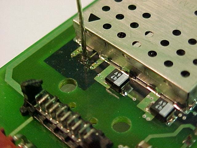
Click to zoom
Application Details
- Equipment Class
- DSS - Part 15 Spread Spectrum Transmitter
- Date of Grant
- Dec 05, 2005
- Application Purpose
- Original Equipment
- Date of Application
- Dec 05, 2005
- Equipment Note
- Transceiver Module
- Frequency Range
- 902.00000000 - 928.00000000
- Company
- Graco Inc
- Country
- United States
Documents & Files
Document Text
Text extracted from the exhibit documents filed with the FCC. Open a document above to read the original.
Users Manual
USER INSTALLATION MANUAL Graco GNET FHSS RF Transceiver Module TABLE OF CONTENTS 1.0 SCOPE.......................................................................................................3 2.0 REVISION CONTROL ...............................................................................3 3.0 APPLICABLE DOCUMENTS .....................................................................3 4.0 DESCRIPTION...........................................................................................4 5.0 ELECTRICAL SPECIFICATIONS ..............................................................4 6.0 CONNECTOR PINOUT..............................................................................4 7.0 MOUNTING LOCATION ............................................................................5 8.0 ANTENNAS................................................................................................5 9.0 LABELING REQUIREMENTS....................................................................6 10.0 RF EXPOSURE .........................................................................................6 11.0 FCC NOTIFICATIONS ...............................................................................7 1.0 SCOPE This manual covers the necessary items to install a Graco GNET FHSS RF Transceiver Module into a piece of host equipment. Antenna considerations, electrical specifications, and labeling requirements are addressed. 2.0 REVISION CONTROL DATE CHANGES REVISION 3/23/04 ORIGINAL RELEASE 0.0 3.0 APPLICABLE DOCUMENTS 248292 RF Board 248293 RF Daughter Board 4.0 DESCRIPTION The Graco GNET FHSS RF Transceiver Module is a frequency hopping spread spectrum transceiver capable of 2-way transportation of message packets in the 900 MHz ISM band. A standard serial interface operating at 3 volts CMOS levels is used to communicate with the host device. Exact protocol and messaging details are available in the Graco GNET FHSS RF Transceiver Module Host Interface Protocol document. The host device supplies power through the interface connector in accordance with the operating voltage and current requirements. 5.0 ELECTRICAL SPECIFICATIONS The module should be operated within the electrical limits provided in this section. Operation outside of these parameters may damage the unit. Parameter Min Typ Max Units Operating Voltage 8.6 9.6 10.6 VDC Transmit Current 150 200 mA Receive Current 15 mA Sleep Current N/A N/A μA Operating Temperature -40 +85 °C 6.0 CONNECTOR PINOUT J3-1 Power In (9.6 Volts typical) J3-2 Regulator Shutdown Control (Shutdown = 0 volts) J3-3 RX J3-4 TX J3-6 Gnd 7.0 MOUNTING LOCATION In order to maintain compliance with the FCC modular certification it is necessary to mount the module in such a way that user is never closer than 20 cm to the antenna. The manual for end users of the product must contain a warning about the 20 cm separation as outlined in Section 10.0. Additionally, the transceiver may not be co-located with any other antenna or transmitter. 8.0 ANTENNAS Compliance with FCC regulations may only be maintained using the specified antennas. The orientation of the antennas is controlled as a requirement on the engineering documentation. Re: 248292 RF Board 248293 RF Daughter Board The specified wire antenna will be attached at the factory and should not be altered. 9.0 LABELING REQUIREMENTS The FCC requires that the Part 15 statement be installed on the outside of the final product in a manner which allows it to be seen and read. The accepted statement and a sample label format are as follows: This device complies with Part 15 of the FCC Rules. Operation is subject to the following two conditions: 1. This device may not cause harmful interference, and 2. This device must accept any interference received, including interference that may cause undesired operation. Contains FCC ID: JHIGNET IC: 4840A-GNET MODEL: XXXXXX Graco Inc. P.O. Box 1441 Minneapolis, MN 55440, U.S.A. The label should be printed or molded into the case using a type front and size that is readable with the unaided eye. The FCC identification number is required. 10.0 RF EXPOSURE This module has been designed to comply with FCC RF exposure requirements outlined in Parts 2.1091, 2.1093, and 15.247(b)(4). Deviation from the recommended installation may violate RF exposure requirements. The Graco GNET RF Transceiver Module is limited in application to products “generally used in such a way that a separation distance of at least 20 centimeters is normally maintained between the transmitter’s radiating structure(s) and the body of the user and nearby persons.” 11.0 FCC NOTIFICATIONS The Graco GNET FHSS RF Transceiver Module generates radio frequency energy. It must be installed according to the manufacturer’s guidelines or it has the potential to cause interference with other radio devices. Testing has been performed to assure that it conforms to the FCC Part 15 rules for intentional and unintentional radiators. No further EMI compliance testing of the transmitter is required as long as the 20 cm separation and co-location requirements are observed. Each new use of the module will, however, always need to be scanned for unintentional radiation from digital clocks, etc. All necessary calibration has been performed at the time of manufacture. Any modification of the device after it leaves the factory is a violation of FCC rules. Compliance Statement (Part 15.19) This device complies with Part 15 of the FCC Rules and with RSS-210 of Industry Canada. Operation is subject to the following two conditions: 1. This device may not cause harmful interference, and 2. This device must accept any interference received, including interference that may cause undesired operation. Warning (Part 15.21) Changes or modifications not expressly approved by the party responsible for compliance could void the user’s authority to operate the equipment. RF Exposure (OET Bulletin 65) To comply with FCC RF exposure requirements for mobile transmittin…
Text truncated - open the document above for the full version.
Cover Letter(s)
GRACO INC. | P.O. Box 1441 | Minneapolis, Minnesota 55440-1441 | 612-623-6000 F C C CONFIDENTIALITY Date: 3/23/04 To: FEDERAL COMMUNICATIONS COMMISSION 7435 Oakland Mills Road Columbia, MD 21046 Subject: Request for Non-disclosure for FCC ID: JHIGNET . To Whom It May Concern: Pursuant to 47 CFR Section 0.459, Graco Inc. & Subsidiaries hereby requests non- disclosure and confidential treatment of the following materials submitted in support of FCC certification application for FCC ID # JHIGNET . a. Schematic Diagrams b. Operational Description c. Block Diagram Above materials contain trade secrets, proprietary and technical information which would customarily be guarded from competitors under 47 CFR section 0.457(d)(2). Disclosure or publication of any portion of this company confidential material to other parties could cause substantial competitive harm and provide unjustified benefits for competitors. Graco Inc. & Subsidiaries understands that pursuant to 47 CFR section 0.457(d)(1)(ii) disclosure of the applicant and all accompanying documentation will not be made before the date of the grant. Sincerely Yours, Douglas Rivord Product Safety and Compliance Administrator
Cover Letter(s)
Hello Jim, I have discussed this issue with Jon Curtis and he thinks that's a good idea to test the worst case. So we'll be okay if the testing was done with 3.0VDC so that it can produce maximum power output. A brief explanation in the report will be needed, so that it's noted officially. If you have more questions let us know please. Best Regards, Yunus Faziloglu Reviewing Engineer Curtis-Straus TCB ----- Original Message ----- From: "Jim Blaha" <[email protected]> To: <[email protected]> Sent: Tuesday, December 09, 2003 3:22 PM Subject: FW: Telecon with Curtis Strauss - Eunice 12/9/2003 > Per our Phone Discussions > > James Blaha > Sr. Vice-President > Quality Manager > L. S. Compliance, Inc. > W66 N220 Commerce Court > Cedarburg, Wisconsin 53012 > Phone: 262-375-4400 x104 > Fax: 262-375-4248 > > This message and the information contained herein are the proprietary > and confidential property of L. S. Compliance, Inc. and may be > privileged. If you are not the intended recipient, please do not read, > copy, disclose or > distribute its contents to any party, and notify the sender > immediately. > > > -----Original Message----- > From: Marc L Denis [mailto:[email protected] ] > Sent: Tuesday, December 09, 2003 9:42 AM > To: Jim Blaha > Subject: Telecon with Curtis Strauss - Eunice 12/9/2003 > > Jim, > > Here are my recollections of the telecon of this morning to Eunice. > > Our client wants a modular certification. Their design incorporates > our XETI core IP and adds a connector and a DC-DC Converter. The DC > Converter manages the conversion of a nominal 9.6 VDC battery voltage > to our nominal 3.0 VDC. Graco developed the DC-DC converter and > selected a design which is rated at 400 mA coninuous. > > In their application, the transmitter is active only briefly and so > even though the DC-DC converter is rated at 400 mA continuous duty, at > their duty cycle it can supply the current required to allow the > transmitter to reach the +27dBm potential of the design at 3.0 Vdc. > However, their continuous duty application presents a practical > problem in that we can't easily test the module to the worst case > emissions using their DC-DC converter. So, the question posed was, > "May we use a lab supply to provide the 3.0 VDC so that we can test > the module to its rated power output without suffering a sagging > supply.? > > As I understood Eunice's response, "Yes we may." We will need to > explain whay we bypassed the DC-DC converter in the test report. > > If you feel additions or clarifications are required to make these > minutes accurate, please do so. > > Regards, > > Marc Denis > x111 >
Cover Letter(s)
GRACO INC. | P.O. Box 1441 | Minneapolis, Minnesota 55440-1441 | 612-623-6000 15 July 2005 Federal Communications Commission 445 Twelfth St., SW Washington, D.C. 20554 Subject: Reason for Two Assembly Numbers, FCC ID: JHIGNET This letter is to communicate the reason for reference of two model numbers (248293, 248294) in the User Installation Manual. It is necessary to have separate model numbers for two distinct configurations to provide for different mounting requirements of the host products. The RF design and function of the two models are identical. It is intended that the application cover both configurations. Regards, Mark King Senior Project Engineer Lubrication Equipment Division cc: Jim Blaha, L.S. Compliance
Cover Letter(s)
GRACO INC. | P.O. Box 1441 | Minneapolis, Minnesota 55440-1441 | 612-623-6000 15 July 2005 Federal Communications Commission 445 Twelfth St., SW Washington, D.C. 20554 Subject: Confirmation of Module Design, FCC ID: JHIGNET This letter is to confirm the fact that, since assembly of the Test Report for our RF module in early 2004, no design, component or manufacturing changes have been made. The current unit for production is the same as the unit initially tested. Regards, Mark King Senior Project Engineer Lubrication Equipment Division cc: Jim Blaha, L.S. Compliance
Cover Letter(s)
To Whom it May Concern: The following is justification for Graco GNet Transceiver Module application for “Radio Module Approval”, set forth in the requirements and policies of the authorization of unlicensed, low power “transmitter modules” for operation under Part 15 of the Commission’s Rules. “Radio Module Approval” is sought with the understanding that the Graco GNet Transceiver Module is designed only with Graco products. Over the years, the Office of Engineering and Technology (OET) has, on a limited number of occasions, granted approval of modular transmitter circuitry that could be used in a variety of Part 15 devices without requiring those devices to obtain subsequent and separate FCC approvals. Such approvals have been granted in an effort to afford relief to equipment manufacturers by eliminating the requirement that a new equipment authorization be obtained for the same transmitter when it is installed in a new device. More recently, a number of manufacturers have requested information about the conditions under which such modular approvals might be granted. This Public Notice sets forth the requirements for approval of modular transmitter equipment designs. These requirements are in addition to what is normally required for an application for an intentional radiator. Several factors should be considered when seeking an equipment authorization for modular transmitters: (a) In order to be considered a transmitter module, the device must be a complete RF transmitter, i.e., it must have its own reference oscillator (e.g., VCO), antenna, etc. The only connectors to the module, if any, may be power supply and modulation/data inputs. The Graco GNet Transceiver Module is a single printed wiring board that implements a self contained, complete wireless interface module. The radio section utilizes a Xemics XE1203 radio chip which uses an on-board reference crystal of 39.000 MHz. The XE1203 chip drives an on-board power amplifier whose power output is regulated via a reference voltage controlled by the on-board microprocessor. The output of the amplifier is fed to an antenna switch and a low pass filter to the solder-attached wire antenna. The only connectors to the module are for DC power and serial data connectivity. (b) Compliance with FCC RF Exposure requirements may, in some instances, limit the output power of a module and/or the final applications in which the approved module may be employed. The Graco GNet Transceiver Module is limited in output power to 23 dBm max with a typical value of 22.5 dBm. This level is controlled via factory calibration. Calibration constants are stored in FLASH memory in the on-board microprocessor and are not accessible to the user. (c) While the applicant for a device into which an authorized module is installed is not required to obtain a new authorization for the module, this does not preclude the possibility that some other form of authorization or testing may be required for the device (e.g., a WLAN into which an authorized module is installed must still be authorized as a PC peripheral, subject to the appropriate equipment authorization). The Graco GNet Transceiver Module is designed to be mounted in a variety of plastic enclosures depending upon the device requiring wireless communication. The only variation in the module is the shape of the attached antenna. The antenna shape is specified in manufacture for the desired application. (d) In the case of a modular transceiver, the modular approval policy only applies to the transmitter portion of such devices. Pursuant to Section 15.101(b), the receiver portion will either be subject to Verification, or it will not be subject to any authorization requirements (unless it is a Scanning Receiver, in which case it is also subject to Certification, pursuant to Section 15.101(a)). (e) The holder of the grant of equipment authorization (Grantee) of the module is responsible for the compliance of the module in its final configuration, provided that the OEM, integrator, and/or end user has complied with all of the instructions provided by the Grantee which indicate installation and/or operating conditions necessary for compliance. The Graco GNet Transceiver Module is designed to be used internally only in Graco products. In order to obtain a modular transmitter approval, a cover letter requesting modular approval must be submitted and the numbered requirements identified below must be addressed in the application for equipment authorization. ______________________________________________________________________________________________________________ 1) The modular transmitter must have its own RF shielding. This is intended to ensure that the module does not have to rely upon the shielding provided by the device into which it is installed in order for all modular transmitter emissions to comply with Part 15 limits. It is also intended to prevent coupling between the RF circuitry of the module and any wires or circuits in the device into which the module is installed. Such coupling may result in non-compliant operation. The Graco GNet Transceiver Module is a completely self contained radio module which has its own RF shielding. No additional shielding is required or implemented. 2) The modular transmitter must have buffered modulation/data inputs (if such inputs are provided) to ensure that the module will comply with Part 15 requirements under conditions of excessive data rates or over-modulation. The Graco GNet Transceiver Module is a completely self contained module which modulates its own RF transmitter. It controls the data flow to the transmitter section compliant with Part 15 requirements. 3) The modular transmitter must have its own power supply regulation. This is intended to ensure that the module will comply with Part 15 requirements regardless of the design of the power supplying circuitry in the device into which the module is installed. The Graco GNet Transceiver Module has its own on-board…
Text truncated - open the document above for the full version.
External Photos
Graco Incorporated FHSS Module 902 - 928 MHz Digital Radio FCC ID#: JHI GNET Photo One – External Module configuration with Wire Antenna configured above PCB Graco Incorporated FHSS Module 902 - 928 MHz Digital Radio FCC ID#: JHI GNET Photo Two – External Module configuration with Wire Antenna configured extended parallel to PCB Graco Incorporated FHSS Module 902 – 928 MHz Digital Radio FCC ID#: JHIGNET Photo Three – External Close-up of FCC ID Label on the Modules Shielding Surface Graco Incorporated FHSS Module 902 - 928 MHz Digital Radio FCC ID#: JHI GNET Photo Four – External Another view of the Wire Antenna above the PCB Graco Incorporated FHSS Module 902 - 928 MHz Digital Radio FCC ID#: JHI GNET Photo Five – External Angle view of the Wire Antenna above the PCB Graco Incorporated FHSS Module 902 - 928 MHz Digital Radio FCC ID#: JHI GNET Photo Six – External Close up of Wire Antenna Attachment This applies for both Above and Parallel Antennas Graco Incorporated FHSS Module 902 - 928 MHz Digital Radio FCC ID#: JHI GNET Photo Seven – External Close up of Wire Antenna Attachment This represents the parallel Antenna Configuration
ID Label/Location Info
FCC ID: JHIGNET IC: 4840A-GNET F e d e r a l C o m m u n i c a t i o n C o m m i s s i o n U S A Scale - 4:1 FCC ID: JHIGNET IC: 4840A-GNET F e d e r a l C o m m u n i c a t i o n C o m m i s s i o n U S A Scale - 4:1 248292 248293
Internal Photos
Graco Incorporated FHSS Module 902 - 928 MHz Digital Radio FCC ID#: JHI GNET Photo One - Internal Open for Inspection – Shielding removed from RF Section Graco Incorporated FHSS Module 902 - 928 MHz Digital Radio FCC ID#: JHI GNET Photo Two - Internal Close up of Bottom of PCB Graco Incorporated FHSS Module 902 - 928 MHz Digital Radio FCC ID#: JHI GNET Photo Three - Internal Another Close up View of the Wire Antenna Connection
RF Exposure Info
Prediction of MPE limit at a given distance Equation from page 18 of OET Bulletin 65, Edition 97-01 where:S = power density P = power input to the antenna G = power gain of the antenna in the direction of interest relative to an isotropic radiator R = distance to the center of radiation of the antenna Maximum peak output power at antenna input terminal:23.00(dBm) Maximum peak output power at antenna input terminal:199.5262315(mW) Antenna gain(typical):0(dBi) Maximum antenna gain:1(numeric) Prediction distance:20(cm) Prediction frequency:915(MHz) MPE limit for uncontrolled exposure at prediction frequency:0.61(mW/cm^2) Power density at prediction frequency:0.039694(mW/cm^2) Maximum allowable antenna gain:11.8659969(dBi) Margin of Compliance at 20cm =15.04dB 2 4R PG S π =
Test Report
TITLE: GNet MODULE CONDUCTED TESTS PROJECT: Gnet RADIO MODULE DEVELOPMENT W66 N220 COMMERCE COURT CEDARBURG, WI 53012, USA (262)-375-4400 FAX: (262)-375-6731 email: [email protected], http://www.lsr.com DRAWN BY: MARC DENIS, SR RF ENG DATE: May 4, 2005 CHECKED BY: BRIAN PETTED, VP ENG DATE: May 4, 2005 APPROVED BY: BRIAN PETTED, VP ENG DATE: May 4, 2005 SIZE: A DRAWING NUMBER: GRC01ETP REVISION: 0.2 FILENAME, FILES AFFECTED: GRC01ETP_v0.2.doc SCALE: NOT TO SCALE SHEET: 1 OF 32 Graco Corporation GNet Transceiver Module CONDUCTED EMISSION TESTING TITLE: GNet MODULE CONDUCTED TESTS PROJECT: Gnet RADIO MODULE DEVELOPMENT W66 N220 COMMERCE COURT CEDARBURG, WI 53012, USA (262)-375-4400 FAX: (262)-375-6731 email: [email protected], http://www.lsr.com DRAWN BY: MARC DENIS, SR RF ENG DATE: May 4, 2005 CHECKED BY: BRIAN PETTED, VP ENG DATE: May 4, 2005 APPROVED BY: BRIAN PETTED, VP ENG DATE: May 4, 2005 SIZE: A DRAWING NUMBER: GRC01ETP REVISION: 0.2 FILENAME, FILES AFFECTED: GRC01ETP_v0.2.doc SCALE: NOT TO SCALE SHEET: 2 OF 32 TABLE OF CONTENTS 1.0 SIGNATURES............................................................................................3 2.0 SCOPE.......................................................................................................5 3.0 REVISION CONTROL ...............................................................................5 4.0 APPLICABLE DOCUMENTS .....................................................................6 5.0 EQUIPMENT UNDER TEST CONDITIONS (CONDUCTED EMISSIONS)8 5.1 Output Power and Occupied Bandwidths15.247(a) (b) (c) : .................9 5.1.1 Minimum Channel Separation (Part 15.247(a)(1)).........................10 5.1.2 Equal Channel Usage (Part 15.247(a)(1)) .....................................12 5.1.3 Pseudorandom Hopping Pattern (Part 15.247(a)(1)).....................12 5.1.4 Receiver Synchronization (Part 15.247(a)(1)) ...............................12 5.1.5 Receiver Input Bandwidth (Part 15.247(a)(1)) ...............................12 5.1.6 Number of Hopping Frequencies (Part 15.247(a)(1)(i)).................13 5.1.7 Dwell Time (Part 15.247(a)(1)(i)) ...................................................19 5.1.8 20dB Bandwidth (Part 15.247(a)(1)(i)) ...........................................20 5.1.9 Peak Output Power (Part 15.247(b)(2)..........................................21 5.1.10 EIRP Limit (Part15.247(b)(3))........................................................23 5.1.11 Maximum Permissible Exposure (Part 15.247(b)(4)))....................23 5.1.12 Spurious Emission at Band Edges (Part 15.247(c))......................24 5.1.13 Spurious Emission, Wideband (Part 15.247(c)) .............................26 5.1.14 Output Power versus Voltage Supply (Part 15.31 (e) )..................28 5.2 UTILIZATION OF ALL CHANNELS (Part 15.247 (g) )..........................31 5.3 NON-INCORPORATION OF INTELLIGENCE TO SET CHANNELS (Part 15.247 (h) ) .............................................................................................32 TITLE: GNet MODULE CONDUCTED TESTS PROJECT: Gnet RADIO MODULE DEVELOPMENT W66 N220 COMMERCE COURT CEDARBURG, WI 53012, USA (262)-375-4400 FAX: (262)-375-6731 email: [email protected], http://www.lsr.com DRAWN BY: MARC DENIS, SR RF ENG DATE: May 4, 2005 CHECKED BY: BRIAN PETTED, VP ENG DATE: May 4, 2005 APPROVED BY: BRIAN PETTED, VP ENG DATE: May 4, 2005 SIZE: A DRAWING NUMBER: GRC01ETP REVISION: 0.2 FILENAME, FILES AFFECTED: GRC01ETP_v0.2.doc SCALE: NOT TO SCALE SHEET: 3 OF 32 1.0 SIGNATURES Manufacturer: Graco Date(s) of Test: November 24, 2003, and May 4, 2005 Test Engineer: Marc Denis Model #: Serial #: 101 Operating Mode: Hopping / CW, as required per individual test Prepared By: Teresa A. White, Document Coordinator Date Tested By: signed by Marc L Denis, P.E. Marc L Denis, P.E., Sr. RF Engineer PE # 916164 Licensed Professional Engineer Registered in the State of Minnesota, United States Approved By: signed by Brian E. Petted Brian E. Petted, VP Engineering Date TITLE: GNet MODULE CONDUCTED TESTS PROJECT: Gnet RADIO MODULE DEVELOPMENT W66 N220 COMMERCE COURT CEDARBURG, WI 53012, USA (262)-375-4400 FAX: (262)-375-6731 email: [email protected], http://www.lsr.com DRAWN BY: MARC DENIS, SR RF ENG DATE: May 4, 2005 CHECKED BY: BRIAN PETTED, VP ENG DATE: May 4, 2005 APPROVED BY: BRIAN PETTED, VP ENG DATE: May 4, 2005 SIZE: A DRAWING NUMBER: GRC01ETP REVISION: 0.2 FILENAME, FILES AFFECTED: GRC01ETP_v0.2.doc SCALE: NOT TO SCALE SHEET: 4 OF 32 Approved By: Kenneth L. Boston, EMC Lab Manager Date PE # 31926 Licensed Professional Engineer Registered in the State of Wisconsin, United States TITLE: GNet MODULE CONDUCTED TESTS PROJECT: Gnet RADIO MODULE DEVELOPMENT W66 N220 COMMERCE COURT CEDARBURG, WI 53012, USA (262)-375-4400 FAX: (262)-375-6731 email: [email protected], http://www.lsr.com DRAWN BY: MARC DENIS, SR RF ENG DATE: May 4, 2005 CHECKED BY: BRIAN PETTED, VP ENG DATE: May 4, 2005 APPROVED BY: BRIAN PETTED, VP ENG DATE: May 4, 2005 SIZE: A DRAWING NUMBER: GRC01ETP REVISION: 0.2 FILENAME, FILES AFFECTED: GRC01ETP_v0.2.doc SCALE: NOT TO SCALE SHEET: 5 OF 32 2.0 SCOPE This report presents the results associated with the conducted emission tests of the Graco Gnet RF Transceiver Module. This particular module is configured for 902-928 MHz operation. This report presents conducted test results required for pre-compliance for authorization under FCC Part 15.247 as a potential frequency hopping device. 3.0 REVISION CONTROL DATE CHANGES REVISION 4/8/2004 ORIGINAL RELEASE 0.0 5/4/2005 EDIT SECTION 5.1.11 TO CHANGE DISTANCE TO 20 CM 0.1 5/4/2005 ADD SECTION 5.1.14 TO ADDRESS 15.31 (E) 0.1 5/4/2005 ADD SECTION 5.2 TO ADDRESS 15.247 (G) 0.1 5/4/2005 ADD SECTION 5.3 TO ADDRESS 15.247 (H) 0.1 5/4/2005 TEST EQUIPMENT LISTING ADDED 0.1 10/03/5 TCB REVISIONS 0.2 TITLE: GNet MODULE CONDUCTED TESTS PROJECT: Gnet RADIO MODULE DEVELOPMENT W66 N220 COMMERCE COURT CEDARBURG, WI 53012, USA (262)-375-4400 FAX: (262)-375-6731 email: [email protected], http://www.lsr.co…
Text truncated - open the document above for the full version.
Test Report
L.S. Compliance, Inc. W66 N220 Commerce Court Cedarburg, WI 53012 262-375-4400 Fax: 262-375-4248 COMPLIANCE TESTING OF: GNET PREPARED FOR: Graco, Inc. Minneapolis, MN 55440 TEST REPORT NUMBER: 304121 TCB Rev. 1 TEST DATE(S): February and March 2004 All results of this report relate only to the items that were tested. This report is not to be reproduced, except in full, without written approval of L. S. Compliance, Inc. L.S. Compliance, Inc. Page 2 of 27 Test Report Number: 304121 TCB Rev. 1 Prepared For: Graco, Inc. Table of Contents Section Description Test Type Page Index 2 1 L. S. Compliance in Review 3 2 A2LA Certificate of Accreditation 4 3 A2LA Scope of Accreditation 5 4 Validation Letter-U.S. Competent Body for EMC Directive 89/336/EEC 6 5 Signature Page 7 6 Product and General Information 8 7 Product Description 8 8 Test Requirements 8 9 Summary of Test Report 9 10 Introduction 9 11 Purpose 9 12 Radiated Emissions Test FCC 10-21 13 Conducted Emissions Test, AC Power Line 22-26 Appendix A Test Equipment List 27 B Conducted Emissions Test Report (LSR) Attached L.S. Compliance, Inc. Page 3 of 27 Test Report Number: 304121 TCB Rev. 1 Prepared For: Graco, Inc. 1. L. S. Compliance In Review Brief Review of L.S. Compliance Accreditations and Listing’s As an EMC Testing Laboratory, our Accreditation and Assessments are recognized through the following: A2LA – American Association for Laboratory Accreditation Accreditation based on ISO/IEC 17025 : 1999 with Electrical (EMC) Scope of Accreditation A2LA Certificate Number: 1255.01 Federal Communications Commission (FCC) – USA Listing of 3 Meter Semi-Anechoic Chamber based on Title 47 CFR – Part 2.948 FCC Registration Number: 90756 Listing of 3 and 10 meter OATS based on Title 47CFR – Part 2.948 FCC Registration Number: 90757 Industry Canada On file, 3 Meter Semi-Anechoic Chamber based on RSS-212 – Issue 1 File Number: IC 3088-A On file, 3 and 10 Meter OATS based on RSS-212 – Issue 1 File Number: IC 3088 U. S. Conformity Assessment Body (CAB) Validation Validated by the European Commission as a U. S. Competent Body operating under the U. S. /EU, Mutual Recognition Agreement (MRA) operating under the European Union Electromagnetic Compatibility –Council Directive 89/336/EEC, Article 10.2. Date of Validation: January 16, 2001 Validated by the European Commission as a U.S. Notified Body operating under the U.S./EU, Mutual Recognition Agreement (MRA) operating under the European Union Telecommunication Equipment – Council Directive 99/5/EC, Annex V. Date of Validation: November 20, 2002 Notified Body Identification Number: 1243 L.S. Compliance, Inc. Page 4 of 27 Test Report Number: 304121 TCB Rev. 1 Prepared For: Graco, Inc. 2. A2LA Certificate of Accreditation L.S. Compliance, Inc. Page 5 of 27 Test Report Number: 304121 TCB Rev. 1 Prepared For: Graco, Inc. 3. A2LA Scope of Accreditation L.S. Compliance, Inc. Page 6 of 27 Test Report Number: 304121 TCB Rev. 1 Prepared For: Graco, Inc. 4. Validation Letter – U.S. Competent Body for EMC Directive 89/336/EEC L.S. Compliance, Inc. Page 7 of 27 Test Report Number: 304121 TCB Rev. 1 Prepared For: Graco, Inc. 5. Signature Page Prepared By: May 1, 2005 Teresa A. White, Document Coordinator Date Tested By: May 1, 2005 Thomas T. Smith, EMC Engineer Date Tested By: May 1, 2005 Abtin Spantman, EMC Engineer Date Tested and Approved By: May 1, 2005 Kenneth L. Boston, EMC Lab Manager Date PE #31926 Licensed Professional Engineer Registered in the State of Wisconsin, United States L.S. Compliance, Inc. Page 8 of 27 Test Report Number: 304121 TCB Rev. 1 Prepared For: Graco, Inc. 6. Product and General Information Manufacturer: Graco, Inc. Model No.: GNET Serial No.: Pre-production Description: Transceiver module, 900 MHz F.H.S.S. 7. Product Description The Graco GNET Transceiver is a compact Frequency Hopping Spread Spectrum 900 MHz transceiver. It features low power consumption in receive or standby modes, 0.2 watt of RF output power, simple serial interface and is low cost. It is based on the XEMICS XE1203 transceiver chipset, and the T.I. MSP430 microprocessor. The transceiver is operated with 2 styles of a ¼ wave wire monopole antenna. 8. Test Requirements The above mentioned tests were performed in order to determi…
Text truncated - open the document above for the full version.
Contact Information
Applicant
Kyle Somora(Product Safety and Compliance Engineer)
Test Firm
LS Research, LLCRyan Urness
Technical Specifications
| # | Rule Parts | Frequency Range | Power Output |
|---|---|---|---|
| 1 | 15C | 902 MHz - 928 MHz | 190.00 mW |
Other Applications from Graco Inc
JHICED2
Jan 27, 202017U762
Equipment Class
DSC - Part 15 Security/Remote Control Transmitter
JHICED1
Apr 08, 2010Remote Control
Equipment Class
DSC - Part 15 Security/Remote Control Transmitter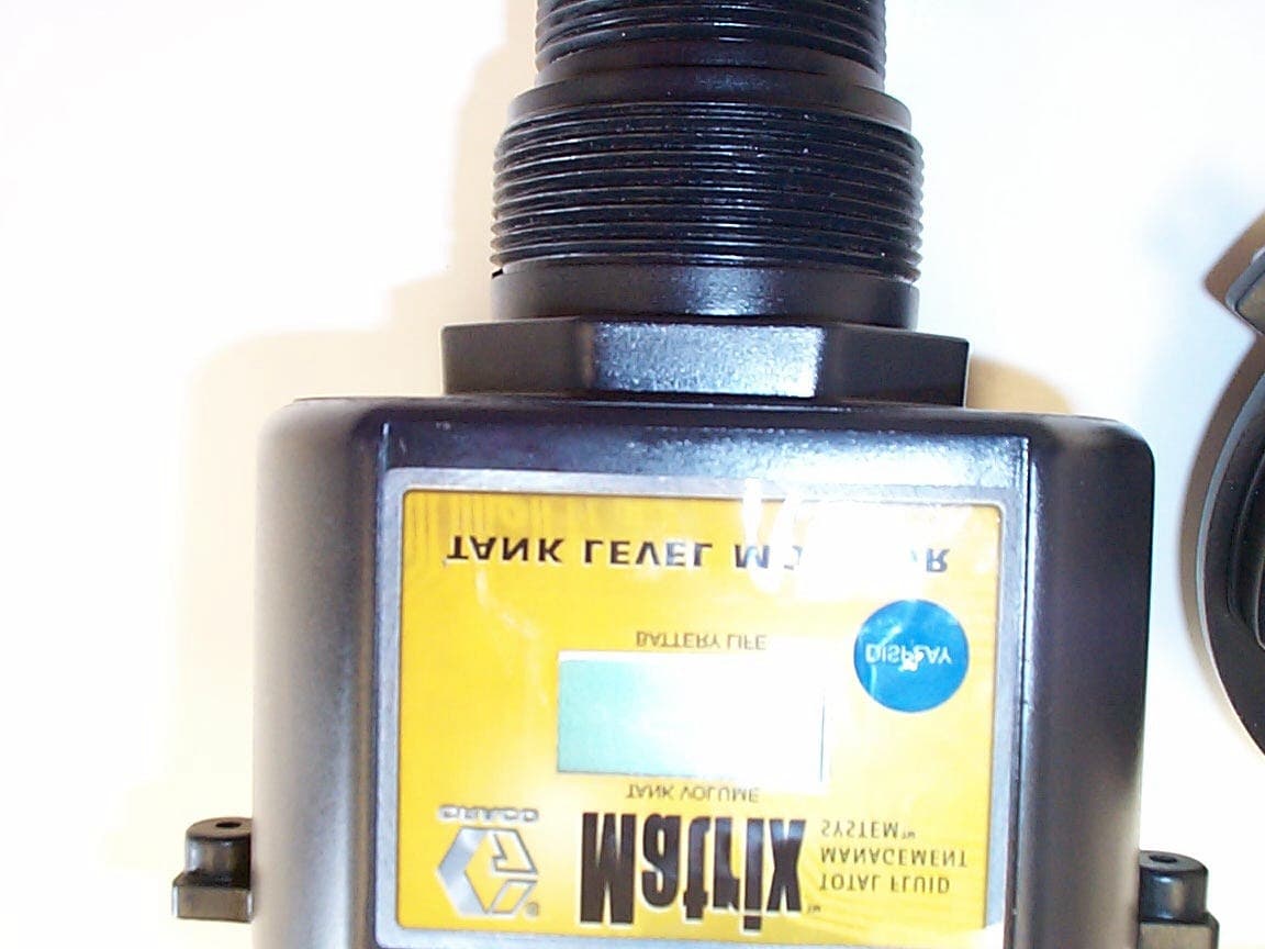
JHITANKTXRX
Sep 10, 2002Matrix Tank Level Monitor
Equipment Class
DXT - Part 15 Low Power Transceiver, Rx Verified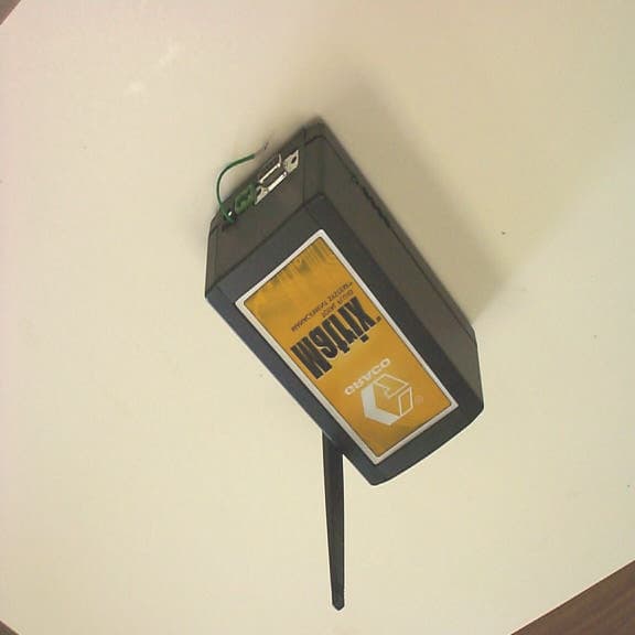
JHITXRX
Sep 09, 2002PC Transceiver or Repeater or Wall Buster
Equipment Class
DXT - Part 15 Low Power Transceiver, Rx Verified
JHIMETERTXRX
Sep 09, 2002Matrix Meter
Equipment Class
DXT - Part 15 Low Power Transceiver, Rx Verified