JRNMOBILINKPaging Transmitter
Scope Communications UK Ltd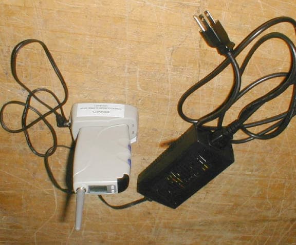
Click to zoom
Application Details
- Equipment Class
- TNT - Licensed Non-Broadcast Transmitter Worn on Body
- Date of Grant
- Jan 03, 2002
- Application Purpose
- Original Equipment
- Date of Application
- Jan 03, 2002
- Equipment Note
- Paging Transmitter
- Frequency Range
- 450.00000000 - 470.00000000
- Company
- Scope Communications UK Ltd
- Country
- United Kingdom
Documents & Files
Document Text
Text extracted from the exhibit documents filed with the FCC. Open a document above to read the original.
Users Manual
PREFACE Important Information It is the purchasers’ responsibility to determine the suitability of this equipment and its derivatives for any given application, Scope cannot give specific advice in this manual, as each use will require independent evaluation. Scope has, wherever possible, employed extra safeguards or designed optional equipment to further monitor the system’s performance. Certain system installations, operational requirements or budgets may, however, limit the effectiveness of these safeguards. Again, the suitability of the system for any given application must therefore be decided by the installer and their customer, relative to the application and risk. Licence This equipment is cleared for use within the USA under a license assigned to the exclusive importer, PIPS Holdings Inc. License No. 950415906. Certain restrictions apply in respect of power output and antenna installations. Alternative frequencies are available by formal license application (Form 600) via the FCC. These may not be subject to the same restrictions as the dockside frequencies. Before operation you should obtain and read the FCC Rules and Regulations, Title 47, Part 80 to End, including Parts 90 and 95, available from the US Government Printing Office, GPO Bookstore or FCC Office. Important Safety Information Scope products are designed to operate safely when installed and used according to general safety practices. The following requirements should be observed at all times. Do NOT subject this equipment to: Mechanical shock Excessive humidity or moisture Extremes of temperature Corrosive liquids This equipment must not be used in classified Hazardous Areas, including areas containing explosive or flammable vapors, unless express authorization has been given in writing by the manufacturer. If in doubt, consult your local product dealer for further information. Only use a damp cloth for cleaning (not liquid or aerosol based cleaners), and ensure that any power is removed from the unit(s) prior to beginning the cleaning operation. Important Safety Information Removal of covers from the equipment/chargers must only be undertaken by authorized service personnel, who must ensure that power is isolated prior to removal. Preface Equipment Applications It is the user’s responsibility to determine the suitability of the Scope products for any given application. Scope or any of its subsidiaries or Distributors, cannot provide specific advice within this manual, as each application will require independent evaluation. Common sense dictates that certain applications may require back up systems in place to cover in the event of mains or equipment failure and all applications should be thoroughly assed by the installer in conjunction with the customer so as to minimize risk. The following information, however, may be of benefit. Scope has no control of the use and application of the frequencies issued by the FCC. Some equipment that is individually licensed may have a greater degree of protection than other equipment that is operated on a FCC dockside frequency. Equipment Testing. Range tests should be carried out at least once a week on portable radio equipment, more often when critical criteria apply. They should involve testing the unit past the limit of its required working range. Good working practice dictates that a suitable system installation log, covering both portable and fixed equipment must be generated, together with a record of the dates when the system has been manually checked and/or serviced, (with the aid of suitable test equipment etc.) enabling the system performance to be compared with the original installation data. The frequency of the tests required will vary between applications. If portable equipment has been dropped or is worn by a person involved in an accident, the unit should be tested again before re-use. It must be stressed that the physical range tests are essential and any construction work or movement of plant or equipment could alter the signaling capability of the unit. Radio equipment like any other requires servicing from time to time to ensure that it is operating to its optimum performance. It is essential that equipment should be inspected and tested by authorized service centers at least once a year. Literature Distributors in conjunction with Scope Marketing, (Communications UK) Ltd., the manufacturer, operate a policy of continual improvement, and therefore reserve the right to modify or change the specifications without prior notice. While every possible care has been taken in the preparation of this manual, Scope shall not be liable for technical or typographical errors or omissions contained herein, nor for incidental or consequential damage arising from the use of this material. Installation Installation must only be undertaken by an Approved contractor, who shall ensure that all work is carried out in compliance with the appropriate State and Federal Regulations. For mains powered equipment, a readily accessible isolating fuse or socket must be located within 1 meter of the equipment. Liability Scope does not accept liability for any damage or injury, howsoever caused as the result of misuse of this equipment. It is the responsibility of the user to ensure that the equipment is operated in the manner for which it was intended and that it is the correct item of equipment for the required task. Warranty This product is warranted as free from defects of workmanship and materials for a period of one year from the original purchase date. During this time, if there is a defect or malfunction of this product, Scope will, with proof of purchase, repair or replace at its discretion any defective parts, free of charge. This does not include where the adjustments, parts and repair are necessary due to circumstances beyond the control of Scope, including but not limited to fire or other casualty, accident, neglect, abuse, abnormal use or battery leakage damage. There are no …
Text truncated - open the document above for the full version.
Cover Letter(s)
American Telecommunications Certification Body Inc. 6731 Whittier Ave, McLean, VA 22101 November 18, 2001 RE: Scope Marketing FCC ID: JRNMOBILINK Your comments have been addressed in the exhibits referred to below, in bold-face type. Thank you, Greg Snyder I have the following comments on this Application. 1.) No parts list was supplied. This is required for any transmitter certified in the licensed services. Please see file “HHUTX Parts List 101.pdf” 2.) RF Exposure report must be broken out separately for uploading to the Commission. Please see file “MPE Report.pdf” 3.) Transient Frequency Response seems to indicate failing data up until T3. FYI: If applying under 90.217, 90.214 would not be required. Please see file “Test Report REV 1.pdf” 4.) Conducted power output does not match 731. Please advise. If antenna is permanent and non-detachable rated power output can be in ERP if so specified on 731. Please see file “Revised Form 731.pdf” 5.) Reference level on Occupied Bandwidth does not match any conducted or radiated power output. Please re-do reference level and Occupied Bandwidth Measurement. Please include appropriate masks as necessary. Please see file “Test Report REV 1.pdf” 6.) Please note the spectrum efficiency standards of 90.203(3). As such, it must meet all of the Rules for 12.5 KHz equipment (Tx Spurious = 50 + 10logP, 90.210 masks for 12.5 KHz equipment, etc.). The only exception would be if the Applicant is applying for Exemption from Technical Standards of 90.217; but it is not clear from the Report this is what you wish to accomplish. Please see file “Test Report REV 1.pdf” 7.) No description of modulation characteristics as required by Part 2 is included in Test Report. Please see file “Test Report REV 1.pdf” 8.) No justification for the requested emission designator using 2M +2DK as required by Part 2 is included in the Test Report. Please see file “Test Report REV 1.pdf” 9.) Transmitter is adjustable to either 2.5 or 4.5 KHz deviation. Please provide Occupied Bandwidth using each setting. Please adjust emission designators as needed. Revise 731. Please see file “Test Report REV 1.pdf” 10.) No RF warning information is given to the end user in manual. No installation instructions. I am unable to determine if I should evaluate this as a Mobile or Portable device according to the definitions of 2.1091 or 2.1093. l Page 2 November 29, 2001 Please see file “Revised Draft of User Manual.pdf” William H. Graff Examining Engineer President and Director of Engineering mailto:[email protected] The items indicated above must be submitted before processing can continue on the above referenced application. Failure to provide the requested information may result in application termination. Correspondence should be considered part of the permanent submission and may be viewed from the Internet after a Grant of Equipment Authorization is issued. Please do not respond to this correspondence using the email reply button. In order for your response to be processed expeditiously, you must submit your documents through the AmericanTCB.com website. Also, please note that partial responses increase processing time and should not be submitted. Any questions about the content of this correspondence should be directed to the sender.
Cover Letter(s)
American Telecommunications Certification Body Inc. 6731 Whittier Ave, McLean, VA 22101 November 29, 2001 RE: Scope Marketing FCC ID: JNRMOBILINK Please review my comments on this revised Application. Please see responses in Bold Face Type. 1.) Please provide FRN for this Applicant. Please see file "Form 731 w FRN.pdf" 2.) Mask C is used on 25 KHz equipment with 4.5 KHz deviation, while Mask D is used on 12.5 KHz equipment with 2.5 KHz deviation. Mask D is not drawn correctly. You will find it much easier if you use a 50 KHz span with 100Hz RBW. Please correct. Please see file "New Plots.pdf" 3.) Transient Frequency Behavior must be done with both 12.5 KHz and 25 KHz settings. Please submit. Be sure to indicate the deviation of the reference signal generator, and filters used in the test receiver for each plot you provide. Please see file "New Plots.pdf" 4.) FYI: Radiated and Conducted transmitter spur data uses the wrong spurious limit. Since the 12.5 KHz limit of 50 + 10log (P) is stricter, you should be using the -20dBm limit. Your test data still shows passing data but your presentation is wrong. William H. Graff President and Examining Engineer mailto: [email protected] The items indicated above must be submitted before processing can continue on the above referenced application. Failure to provide the requested information may result in application termination. Correspondence should be considered part of the permanent submission and may be viewed from the Internet after a Grant of Equipment Authorization is issued. Please do not respond to this correspondence using the email reply button. In order for your response to be processed expeditiously, you must submit your documents through the AmericanTCB.com website. Also, please note that partial responses increase processing time and should not be submitted. Any questions about the content of this correspondence should be directed to the sender.
Cover Letter(s)
American Telecommunications Certification Body Inc. 6731 Whittier Ave, McLean, VA 22101 November 18, 2001 RE: Scope Marketing FCC ID: JRNMOBILINK I have the following comments on this Application. 1.) No parts list was supplied. This is required for any transmitter certified in the licensed services. 2.) RF Exposure report must be broken out separately for uploading to the Commission. 3.) Transient Frequency Response seems to indicate failing data up until T3. FYI: If applying under 90.217, 90.214 would not be required. 4.) Conducted power output does not match 731. Please advise. If antenna is permanent and non-detachable rated power output can be in ERP if so specified on 731. 5.) Reference level on Occupied Bandwidth does not match any conducted or radiated power output. Please re-do reference level and Occupied Bandwidth Measurement. Please include appropriate masks as necessary. 6.) Please note the spectrum efficiency standards of 90.203(3). As such, it must meet all of the Rules for 12.5 KHz equipment (Tx Spurious = 50 + 10logP, 90.210 masks for 12.5 KHz equipment, etc.). The only exception would be if the Applicant is applying for Exemption from Technical Standards of 90.217; but it is not clear from the Report this is what you wish to accomplish. 7.) No description of modulation characteristics as required by Part 2 is included in Test Report. 8.) No justification for the requested emission designator using 2M +2DK as required by Part 2 is included in the Test Report. 9.) Transmitter is adjustable to either 2.5 or 4.5 KHz deviation. Please provide Occupied Bandwidth using each setting. Please adjust emission designators as needed. Revise 731. 10.) No RF warning information is given to the end user in manual. No installation instructions. I am unable to determine if I should evaluate this as a Mobile or Portable device according to the definitions of 2.1091 or 2.1093. William H. Graff Examining Engineer President and Director of Engineering mailto:[email protected] The items indicated above must be submitted before processing can continue on the above referenced application. Failure to provide the requested information may result in application termination. Correspondence should be considered part of the permanent submission and may be viewed from the Internet after a Grant of Equipment Authorization is issued. Please do not respond to this correspondence using the email reply button. In order for your response to be processed expeditiously, you must submit your documents through the AmericanTCB.com website. Also, please note that partial responses increase processing time and should not be submitted. Any questions about the content of this correspondence should be directed to the sender.
Cover Letter(s)
American Telecommunications Certification Body Inc. 6731 Whittier Ave, McLean, VA 22101 November 29, 2001 RE: Scope Marketing FCC ID: JNRMOBILINK Please review my comments on this revised Application. 1.) Please provide FRN for this Applicant. 2.) Mask C is used on 25 KHz equipment with 4.5 KHz deviation, while Mask D is used on 12.5 KHz equipment with 2.5 KHz deviation. Mask D is not drawn correctly. You will find it much easier if you use a 50 KHz span with 100Hz RBW. Please correct. 3.) Transient Frequency Behavior must be done with both 12.5 KHz and 25 KHz settings. Please submit. Be sure to indicate the deviation of the reference signal generator, and filters used in the test receiver for each plot you provide. 4.) FYI: Radiated and Conducted transmitter spur data uses the wrong spurious limit. Since the 12.5 KHz limit of 50 + 10log (P) is stricter, you should be using the -20dBm limit. Your test data still shows passing data but your presentation is wrong. William H. Graff President and Examining Engineer mailto: [email protected] The items indicated above must be submitted before processing can continue on the above referenced application. Failure to provide the requested information may result in application termination. Correspondence should be considered part of the permanent submission and may be viewed from the Internet after a Grant of Equipment Authorization is issued. Please do not respond to this correspondence using the email reply button. In order for your response to be processed expeditiously, you must submit your documents through the AmericanTCB.com website. Also, please note that partial responses increase processing time and should not be submitted. Any questions about the content of this correspondence should be directed to the sender.
External Photos
EUT Overall System, including Cradle and Charger Front View Back View Side View Top View
ID Label/Location Info
IIIIIIIIIIIIIIIIIIIIIIIIII 123456 Scope Marketing (Comms UK) Ltd MODEL: HHTXU1 FCC ID: JRNMOBILINK Scope Marketing (Comms UK) Ltd Ref: HHFCCLABIssue 1 Made in UK Synergie This device complies with part 15 of the FCC Rules. Operation is subject to the following two conditions: (1) this device may not cause harmful interference, and (2) this device must accept any interference received, including interference that may cause undesired operation. Artwork: reduce 2:1 Black lettering on Cool Grey 1C background
Internal Photos
EUT, Cover Removed PCB Top View PCB Bottom View PCB Top, Shield Removed View PCB Bottom, Shield Removed View
Operational Description
HAND-HELD TRANSMITTER CIRCUIT DESCRIPTION AND OPERATING INSTRUCTIONS This transmitter is crystal controlled on a single channel, and can be set up to operate anywhere between approximately 450 and 470 MHz without component changes. The radio frequency generator is a cascade of four transistors. It consists of a third overtone crystal oscillator followed by two frequency tripler stages, driver and power amplifier. The crystal runs at approximately 51 MHz, and subsequent stages are tuned to approximately 153 MHz and 459 MHz. All interstage coupling networks are double tuned band pass filters, and the power amplifier is followed by an eight element low pass network. The entire RF lineup is enclosed in its own screening can to eliminate spurious radiated interference. The output power is fed directly to the base of a shortened helical aerial, and the effective radiated power is estimated to be around 80 milliwatts. The transmitter runs from two internal nickel hydride cells, and is entirely software controlled. Logic signals from the microcontroller are level shifted and low pass filtered before being applied to the frequency modulator. The deviation is internally adjustable, and is normally set to ± 2.5 kHz or ± 4.5 kHz dependent on channel spacing requirements. The data format is non return to zero, frequency shift keying, so that with no modulation the transmitter frequency is offset from the nominal by approximately half the deviation. The transmitter is manually controlled from two blue buttons at the side and two on the top adjacent to the display. Using the current software, the upper blue button cycles through 1. Software and microcontroller running. 2. RF carrier on. 3. Continuous modulation on. To switch off, press the button adjacent to the loudspeaker symbol in the display. The nominal battery capacity is 1.6 ampere hours and given a full charge, should provide three to four hours of continuous carrier for test purposes. However, if it becomes necessary to recharge the battery, place the transmitter in its charger which is supplied. K Jessop 20.06.01
RF Exposure Info
Maximum Permissible Exposure Test Report for Scope Marketing, Ltd. Wills Road, Totnes Industrial Estate Totnes Devon TQ95XN England FCC ID: JRNMOBILINK November 19, 2001 WLL PROJECT #: 6670X This report may not be reproduced, except in full, without the prior written consent of Washington Laboratories, Ltd. Scope Marketing, Ltd FCC ID: JRNMOBILINK WLL Project #: 6670X 1 Maximum Permissible Exposure Test Report for FCC ID: JRNMOBILINK 1.0 Introduction This report has been prepared on behalf of Scope Marketing, Ltd. Model: HHTXU1 transmitter to show compliance with the RF exposure requirements as defined in FCC Part 1.1307. 1.1 Radio Frequency Radiation Exposure The highest RF output power of the unit was measured at 26.2 dBm at 458.7 MHz. According to §1.1310 of the FCC rules, the limit for occupational/controlled RF exposure is defined as S=f/300. For the frequency of 458.7 MHz, the Power Density limit is calculated to be 1.529 mW/cm 2 . The gain of the antenna is –6 dBi. To comply with the exposure limits for this section, humans must maintain a safe distance from the transmit antenna. The following formula was used to calculate the minimum distance: 2 4R PG S π = Where: S = Power Density P = Output Power at the Antenna Terminals G = Gain of Transmit Antenna (linear gain) R = Distance from Transmitting Antenna For this device, the calculation is as follows: S = FCC Limit = 1.529 mW/cm 2 P = Output Power = 426.6 mW G = Worst Case Gain = -6 dBi = INVLOG(-6/10) = 0.251 1.529mW/ cm 2 = (426.6mW)(0.251)/(4π R 2 ) Solving for the required minimum safe distance using the following formula: S PG R π4 = 529.14 251.06.426 ×× × = π R = 2.36 cm (Based on continuous transmission) However, based on the usage of the device, and taking the duty cycle into account, the EUT will transmit a maximum of 600mS in a 6 minute period. Therefore, averaging the power over a 6 minute period gives: 426.6mW x 0.00167 = 0.711mW 529.14 251.0711.0 ×× × = π R = 0.096 cm (Averaging over 6 minutes) Based on the calculation above, the device complies with the minimal permissible exposure requirements using the current antenna-housing configuration.
Test Report
Document 6670-01, Rev. 1 FCC Certification Test Report Washington Laboratories, Ltd November 2001 FCC Certification Test Report for Scope Marketing, Ltd. JRNMOBILINK November 26, 2001 Prepared for: Scope Marketing, Ltd. Wills Road, Totnes Industrial Estate Totnes Devon TQ95XN England Prepared By: Washington Laboratories, Ltd. 7560 Lindbergh Drive Gaithersburg, Maryland 20879 FCC Certification Test Report Document 6670-01, Rev. 1 FCC Certification Test Report Washington Laboratories, Ltd November 2001 FCC Certification Test Program FCC Certification Test Report for the Scope Marketing, Ltd. HHTXU1 Paging Transmitter JRNMOBILINK November 26, 2001 WLL JOB# 6670 Prepared by: Brian J. Dettling Documentation Specialist Reviewed by: Gregory M. Snyder Chief EMC Engineer Document 6670-01, Rev. 1 FCC ID: JRNMOBILINK FCC Certification Test Report Washington Laboratories, Ltd November, 2001 ii Abstract This report has been prepared on behalf of Scope Marketing, Ltd. to support the attached Application for Equipment Authorization. The test report and application are submitted for a Paging Transmitter under Part 90 of the FCC Rules and Regulations. This Federal Communication Commission (FCC) Certification Test Report documents the test configuration and test results for a Scope Marketing, Ltd. HHTXU1 Paging Transmitter. Testing was performed on an Open Area Test Site (OATS) of Washington Laboratories, Ltd, 7560 Lindbergh Drive, Gaithersburg, MD 20879. Site description and site attenuation data have been placed on file with the FCC's Sampling and Measurements Branch at the FCC laboratory in Columbia, MD. Washington Laboratories, Ltd. has been accepted by the FCC and approved by NIST NVLAP (NVLAP Lab Code: 200066-0) as an independent FCC test laboratory. The Scope Marketing, Ltd. HHTXU1 Paging Transmitter complies with the limits for a Paging Transmitter device under Part 90 of the FCC Rules and Regulations. Document 6670-01, Rev. 1 FCC ID: JRNMOBILINK FCC Certification Test Report Washington Laboratories, Ltd November, 2001 iii Table of Contents 1 INTRODUCTION....................................................................................................1 1.1 COMPLIANCE STATEMENT..................................................................................1 1.2 TEST SCOPE.........................................................................................................1 1.3 CONTRACT INFORMATION...................................................................................1 1.4 TEST DATES........................................................................................................1 1.5 TEST AND SUPPORT PERSONNEL..........................................................................1 1.6 ABBREVIATIONS..................................................................................................1 2 EQUIPMENT UNDER TEST..................................................................................2 2.1 EUT IDENTIFICATION & DESCRIPTION.................................................................2 2.2 TEST CONFIGURATION AND TESTING ALGORITHM................................................3 2.3 TEST LOCATION...................................................................................................3 2.4 MEASUREMENTS.................................................................................................3 2.4.1 References..................................................................................................3 2.5 MEASUREMENT UNCERTAINTY............................................................................4 3 TEST EQUIPMENT.................................................................................................4 4 TEST RESULTS.......................................................................................................5 4.1 RF POWER OUTPUT: (FCC PART §2.1046).........................................................5 4.2 OCCUPIED BANDWIDTH: (FCC PART §2.1049)...................................................6 4.3 SPURIOUS EMISSIONS AT ANTENNA TERMINALS (FCC PART §2.1051)...............9 4.4 RADIATED SPURIOUS EMISSIONS: (FCC PART §2.1053)...................................17 4.4.1 Test Procedure.........................................................................................17 4.5 FREQUENCY STABILITY: (FCC PART §2.1055)..................................................19 4.6 TRANSIENT FREQUENCY BEHAVIOR (PART 90.214)............................................20 5 TRANSMITTER ENVIRONMENTAL ASSESSMENT, MAXIMUM PERMISSIBLE EXPOSURE (MPE)............................................................................23 5.1 SCOPE................................................................................................................23 Document 6670-01, Rev. 1 FCC ID: JRNMOBILINK FCC Certification Test Report Washington Laboratories, Ltd November, 2001 iv List of Tables TABLE 1. DEVICE SUMMARY................................................................................................2 TABLE 2: TEST EQUIPMENT LIST.........................................................................................4 TABLE 3. RF POWER OUTPUT.............................................................................................5 TABLE 4. RADIATED SPURIOUS EMISSIONS LIMITS............................................................17 TABLE 5: RADIATED EMISSION TEST DATA (SUBSTITUTION METHOD).............................18 TABLE 6. FREQUENCY DEVIATION AS A FUNCTION OF TEMPERATURE................................19 TABLE 7. FREQUENCY DEVIATION AS A FUNCTION OF VOLTAGE........................................20 List of Figures FIGURE 1. OCCUPIED BANDWIDTH.......................................................................................7 FIGURE 2. CONDUCTED SPURIOUS EMISSIONS, EMISSION MASK C....................................12 FIGURE 3. CONDUCTED SPURIOUS EMISSIONS, 30MHZ TO 470MHZ..................................13 FIGURE …
Text truncated - open the document above for the full version.
Test Report
Conducted Spurious Emissions, Emission Mask D 12.5 KHz Channel, 2.5 KHz Deviation Transient Frequency Behavior, Turn “On”, 12.5 KHz Channel Transient Frequency Behavior, Turn “Off”, 12.5 KHz Channel
Contact Information
Applicant
Simon R Fidler(Managing Director)
Technical Contact
Washington Laboratories, Ltd.Gregory M Snyder
[email protected]301 417 0220
7560 Lindbergh Drive · Gaithersburg, Maryland · United States
Technical Specifications
| # | Rule Parts | Frequency Range | Power Output | Emission | Tolerance |
|---|---|---|---|---|---|
| 2 | 9 | 450 MHz - 470 MHz | 427.00 mW | 6K2F1D | 2.5 ppm |
Other Applications from Scope Communications UK Ltd
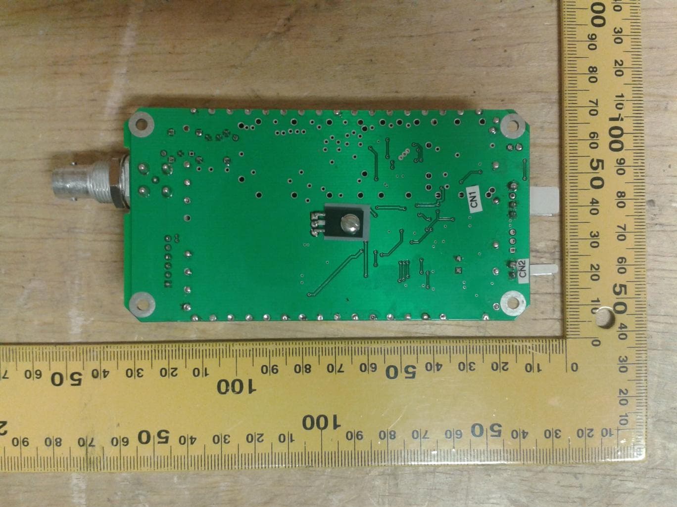
JRNUSA1WTX
Nov 17, 20141 Watt Synthesized UHF Transmitter
Equipment Class
TNB - Licensed Non-Broadcast Station Transmitter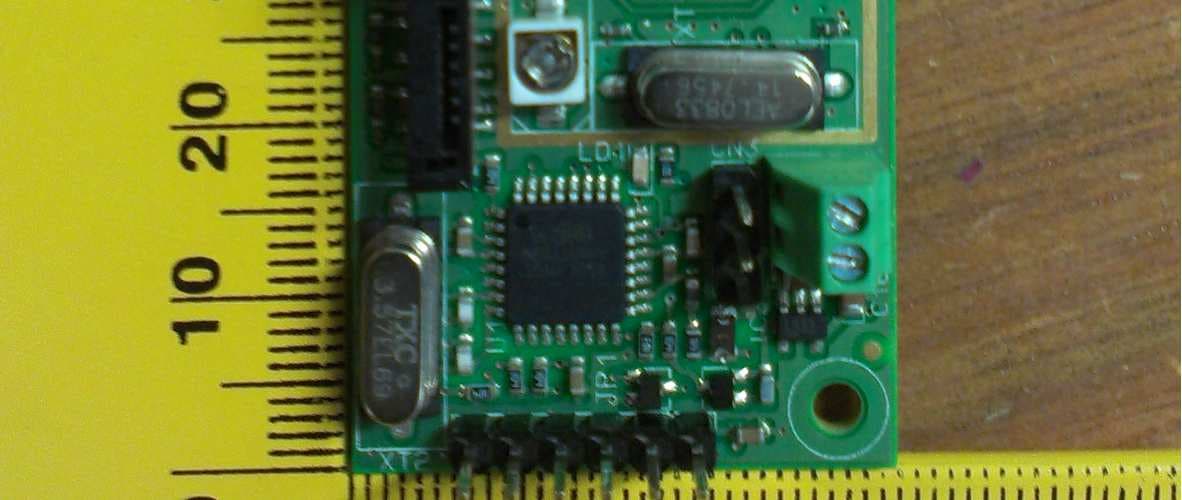
JRNUSAWAVETRACK
Apr 03, 2013LTX1 10mW Lite Transmitter MK1
Equipment Class
TNT - Licensed Non-Broadcast Transmitter Worn on Body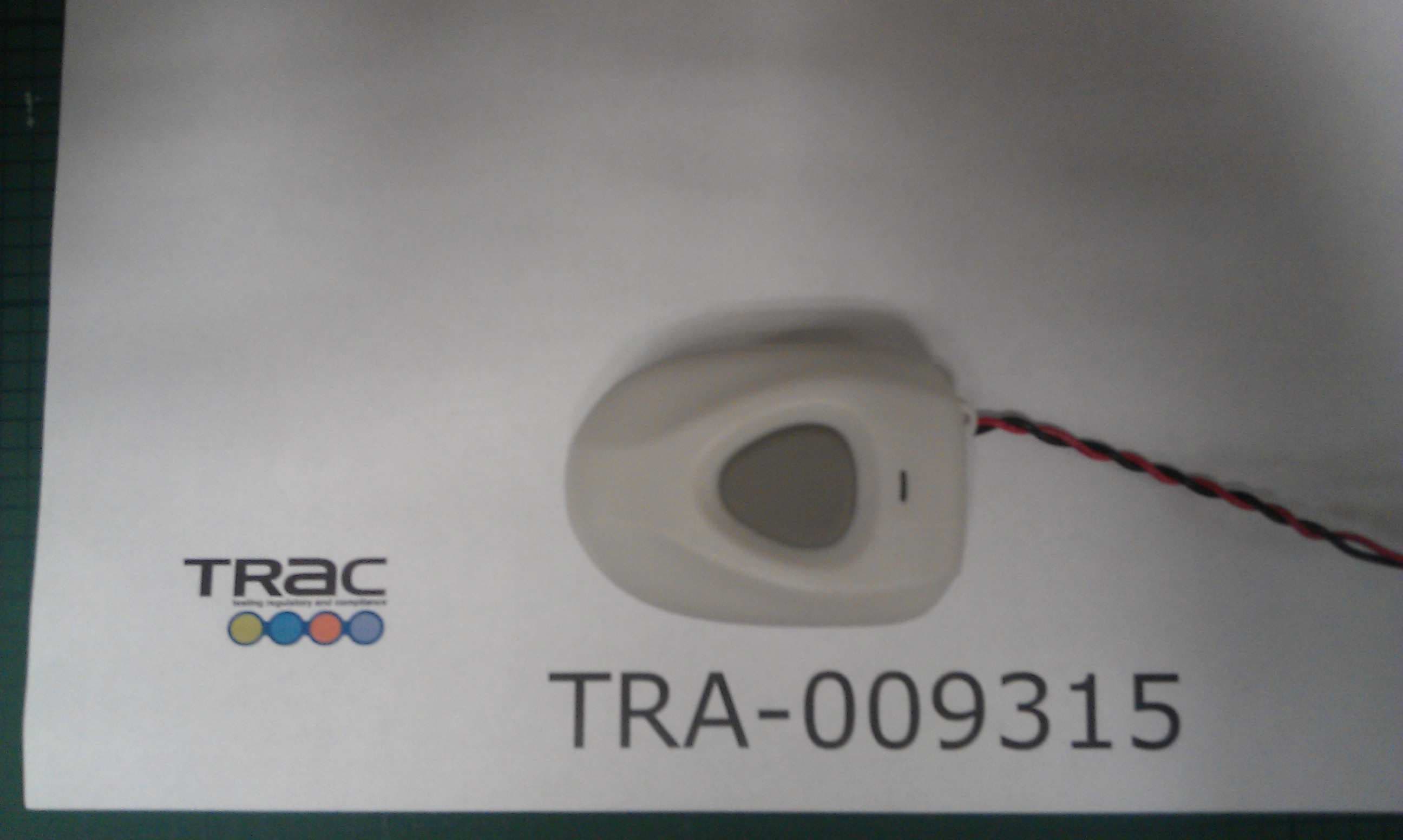
JRNUSAPENLINK
Feb 04, 2013MPA3 Pendant Alarm Transmitter
Equipment Class
TNT - Licensed Non-Broadcast Transmitter Worn on Body
JRNUSAECOLINK
Jan 31, 2007UHF Paging System
Equipment Class
TNB - Licensed Non-Broadcast Station TransmitterJRNUSAAMP1-10
Apr 28, 1997Rated Input Power .465 Watts
Equipment Class
TNB - Licensed Non-Broadcast Station Transmitter