JRNUSAWAVETRACKLTX1 10mW Lite Transmitter MK1
Scope Communications UK Ltd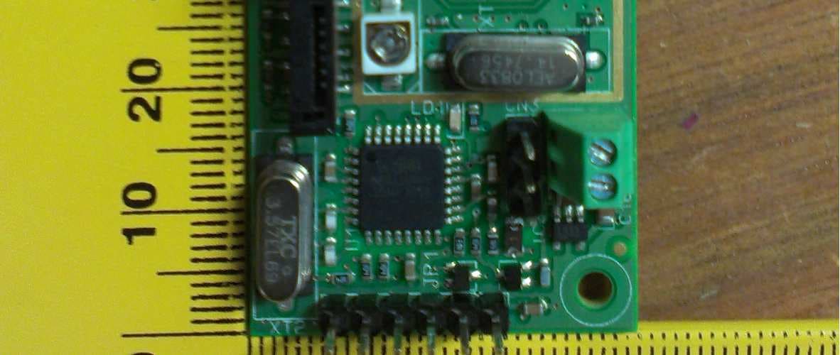
Click to zoom
Application Details
- Equipment Class
- TNT - Licensed Non-Broadcast Transmitter Worn on Body
- Date of Grant
- Apr 03, 2013
- Application Purpose
- Original Equipment
- Date of Application
- Apr 03, 2013
- Equipment Note
- LTX1 10mW Lite Transmitter MK1
- Frequency Range
- 430.00000000 - 470.00000000
- Company
- Scope Communications UK Ltd
- Country
- United Kingdom
Documents & Files
Document Text
Text extracted from the exhibit documents filed with the FCC. Open a document above to read the original.
Users Manual
Scope Communications UK Ltd LPAMAN Issue 1 LTX1 Transmitter User Manual Scope Communications UK Ltd LTX1 Transmitter User Manual LTX1MAN Page 2 of 10 Issue 2 PREFACE Important Installation Information It is the purchasers’ responsibility to determine the suitability of this equipment and its derivatives for any given application, Scope cannot give specific advice in this manual, as each use will require independent evaluation. Scope has, wherever possible, employed extra safeguards to monitor the system’s performance. Certain system installations, operational requirements or budgets may, however, limit the effectiveness of these safeguards. Again, the suitability of the system for any given application must therefore be decided by the installer and their customer, relative to the application and risk. Good working practice dictates that a suitable system installation log must be generated, together with a record of the dates when the system has been manually checked, (with the aid of signal strength meters etc.) enabling the system performance to be compared with the original installation data. For UK equipment, Scope has no control of the use and application of the frequencies issued by OFCOM. Some equipment that is licensed may have greater protection than other equipment which is operated on a WT Act License Exempt basis. The supply of this equipment is governed by our standard terms and conditions of sale, which can be found on the reverse of all order acknowledgements*, proforma invoices*, delivery notes, price lists and invoices. Alternatively, these can be provided on request. * Faxed proforma invoices and quotations refer to “conditions available upon request”. Licence For the UK, this equipment is intended for use on the 433 and 458 MHz Short Range Device licence exempt radio frequencies and programming has been restricted to these ranges. For use in the USA, this equipment will require a licence. Consult your dealer for further advice. For further technical rules governing the use of this equipment you should obtain the FCC Rules and Regulations, Title 47 Part 80 to end, including parts 90 and 95 available from the US Gov Printing Office, GPO Book store, FCC Office or www.fcc.gov/oet/info/rules/ . The FCC ID for this equipment is: JRNUSAWAVETRACK Important Safety Information Scope products are designed to operate safely when installed and used according to general safety practices. The following requirements should be observed at all times. Do NOT subject this equipment to: Mechanical shock Excessive humidity Extremes of temperature Corrosive liquids This equipment is designed primarily for indoor use in a temperature controlled environment. It must not be used in classified Hazardous Areas, including areas containing explosive or flammable vapours. If in doubt, consult your local product dealer for further information. Scope Communications UK Ltd LTX1 Transmitter User Manual LTX1MAN Page 3 of 10 Issue 2 PREFACE Equipment Applications It is the user’s responsibility to determine the suitability of the Scope products for any given application. Scope, including its subsidiaries and Distributors, cannot provide specific advice within this manual, as each application will require independent evaluation. Common sense dictates that certain applications may require back up systems to cover in the event of mains or equipment failure. All applications should be thoroughly assessed by the installer in conjunction with the customer so as to minimize risk. Scope has no control of the use and application of the frequencies issued by the FCC or OFCOM. Some equipment that is individually licensed may have a greater degree of protection than other equipment that is operated on a FCC License Assignment basis. The following information, however, may be of benefit. Equipment Testing Range tests should be carried out at least once a week on portable radio equipment, more often when critical criteria apply. This should involve testing the unit past the limit of its required working range. Good working practice dictates that a suitable system installation log, covering both portable and fixed equipment must be generated, together with a record of the dates when the system has been manually checked and/or serviced, (with the aid of suitable test equipment etc.) enabling the system performance to be compared with the original installation data. The frequency of the tests required will vary between applications. If portable equipment has been dropped or is worn by a person involved in an accident, the unit should be tested again before re-use. It must be stressed that the physical range tests are essential and that any construction work or movement of plant or equipment could alter the signalling capability of the unit. Radio equipment, like any other requires servicing from time to time to ensure that it is operating to its optimum performance. It is therefore essential that equipment is inspected and tested by authorized service centres at least once a year. Literature Scope Communications UK Ltd, the manufacturer, in conjunction with its distributors operates a policy of continual improvement, and therefore reserve the right to modify or change any specifications without prior notice. While every possible care has been taken in the preparation of this manual, Scope does not accept any liability for technical or typographical errors or omissions contained herein, nor for incidental or consequential damage arising from the use of this material. Liability Scope does not accept liability for any damage or injury, howsoever caused as the result of misuse of this equipment. It is the responsibility of the user to ensure that the equipment is operated in the manner for which it was intended and that it is the correct item of equipment for the required task. Scope Communications UK Ltd LTX1 Transmitter User Manual LTX1MAN Page 4 of 10 Issue 2 Warranty This product is warranted as free from defects of workma…
Text truncated - open the document above for the full version.
ID Label/Location Info
LTX1 Transmitter FCC ID Label Position JRNUSAWAVETRACK Underside of pcb shown Ref: FCCW avetrack Issue 1
Test Report
RADIO TEST REPORT FOR SCOPE COMMUNICATIONS UK LTD ON LTX UNIT DOCUMENT NO. TRA-013040-47-00-A Total number of pages: 42 TRaC Wireless Test Report : TRA-013040-47-00-A Applicant : Scope Communications UK Ltd Apparatus : LTX UNIT Specification(s) : CFR47 Part 90.217 Purpose of Test : Certification FCCID : JRNUSAWAVETRACK Authorised by : : Radio Product Manager Issue Date : 1 st March 2013 Authorised Copy Number : PDF TRaC Global Test Report: TRA-013040-47-00-A Contents Section 1: Introduction 4 1.1 General 4 1.2 Tests Requested By 5 1.3 Manufacturer 5 1.4 Apparatus Assessed 5 1.5 Test Result Summary 6 1.6 Notes Relating To The Assessment 7 1.7 Deviations from Test Standards 7 Section 2: Measurement Uncertainty 8 2.1 Measurement Uncertainty Values 8 Section 3: Modifications 10 3.1 Modifications Performed During Assessment 10 Appendix A: Formal Emission Test Results 11 A1 Maximum Radiated Output Power (Effective Radiated Power) 12 A2 Radiated Transmitter Spurious Emissions (ERP) 14 A3 Unintentional Radiated Emissions (Electric Field Strength) 17 A4 Power Line Conducted Emissions 19 A5 Occupied Bandwidth 21 Appendix B: Supporting Graphical Data 25 Appendix C: Additional Test and Sample Details 30 Appendix D: Additional Information 36 Appendix E: Photographs and Figures 37 Appendix F: MPE Calculation 41 3 TRaC Global Test Report: TRA-013040-47-00-A Section 1: Introduction 1.1 General This report contains an assessment of an apparatus against Electromagnetic Compatibility Standards based upon tests carried out on samples submitted to the Laboratory. Test performed by: TRaC Global [ ] Unit E South Orbital Trading Park Hedon Road Hull, HU9 1NJ. United Kingdom. Telephone: +44 (0) 1482 801801 Fax: +44 (0) 1482 801806 TRaC Global [X] Unit 1 Pendle Place Skelmersdale West Lancashire, WN8 9PN United Kingdom Telephone: +44 (0) 1695 556666 Fax: +44 (0) 1695 577077 Email: [email protected] Web site: http://www.tracglobal.com Tests performed by: D Winstanley Report author: D Winstanley This report must not be reproduced except in full without prior written permission from TRaC Global. 4 TRaC Global Test Report: TRA-013040-47-00-A 1.2 Tests Requested By This testing in this report was requested by : Scope Communications UK Ltd Quantum House Totnes Devon TQ9 5AL 1.3 Manufacturer As above. 1.4 Apparatus Assessed The followin g apparatus was assessed between 15 th – 20 th February 2013: LTX UNIT The apparatus is a pendant transmitter for use with an alarm system. The apparatus is designed to transmit between 430 MHz and 470 MHz with a carrier power below 120 mW to allow exemption from the full 47CFR Part 90 technical requirements. 5 TRaC Global Test Report: TRA-013040-47-00-A 1.5 Test Result Summary Full details of test results are contained within Appendix A. The following table summarises the results of the assessment. The statements relating to compliance with the standards below apply ONLY as qualified in the notes and deviations stated in sections 1.6 to 1.7 of this test report. Full details of test results are contained within Appendix A. The following table summarises the results of the assessment. Test Type Regulation Measurement standard Result Maximum Radiated Output Power Title 47 of the CFR: Part 90.217 ASNI/TIA-603-C- 2004 Pass Transmitter Spurious Emissions Radiated (ERP) Title 47 of the CFR: Part 2.1051 ASNI/TIA-603-C- 2004 Pass Unintentional Radiated Spurious Emissions (REFE) Title 47 of the CFR: Part 15 Subpart (b) 15.109 ANSI C63.10:2009 Pass AC Power conducted emissions Title 47 of the CFR: Part 15 Subpart (c) 15.207 ANSI C63.10:2009 N/A Occupied bandwidth/ Frequency Stability Title 47 of the CFR: Part 90.217 (b). ASNI/TIA-603-C- 2004 Pass Abbreviations used in the above table: ANSI C 63.10:2009 and ASNI/TIA-603-C-2004 is outside the scope of the laboratories UKAS accreditation. CFR : Code of Federal Regulations ANSI : American National Standards Institution REFE : Radiated Electric Field Emissions PLCE : Power Line Conducted Emissions 6 TRaC Global Test Report: TRA-013040-47-00-A 1.6 Notes Relating To The Assessment With regard to this assessment, the following points should be noted: The results contained in this report relate only to the items tested and were obtained in the period between the date of initial receipt of samples and the date of issue of the report. The apparatus was set up and exercised using the configurations, modes of operation and arrangements defined in this report only. Particular operating modes, apparatus monitoring methods and performance criteria required by the standards tested to have been performed except where identified in Section 1.7 of this test report (Deviations from Test Standards). For emissions testing, throughout this test report, “Pass” indicates that the results for the sample as tested were below the specified limit (refer also to Section 2, Measurement Uncertainty). Where relevant, the apparatus was only assessed using the monitoring methods and susceptibility criteria defined in this report. All testing was performed under the following environmental conditions: Temperature : 17 to 23 C Humidity : 45 to 75 % Barometric Pressure : 86 to 106 kPa All dates used in this report are in the format dd/mm/yy. This assessment has been performed in accordance with the requirements of ISO/IEC 17025. 1.7 Deviations from Test Standards There were no deviations from the standards test ed to. 7 TRaC Global Test Report: TRA-013040-47-00-A Section 2: Measurement Uncertainty 2.1 Measurement Uncertainty Values For the test data recorded the following measurement uncertainty was calculated: Radio Testing – General Uncertainty Schedule All statements of uncertainty are expanded standard uncertainty using a coverage factor of 1.96 to give a 95% confidence where no required test level exists. [1] Adjacent Channel Power Uncertainty in test result = 1.86dB [2] Carrier Power Uncertainty in test result (Power Meter) = 1.08dB Uncertainty in test result (Spectrum Analyse…
Text truncated - open the document above for the full version.
Test Setup Photos
TRA-013040-02 Test set-up photos
Contact Information
Applicant
Simon R Fidler(Managing Director)
Test Firm
Element Materials Technology Warwick LtdStewart Barrowclough
Technical Specifications
| # | Rule Parts | Frequency Range | Power Output | Emission | Tolerance |
|---|---|---|---|---|---|
| 1 | 90.217 | 430 MHz - 470 MHz | 4.90 mW | 4K08F1D | 1041.0000000000 Hz |
Other Applications from Scope Communications UK Ltd
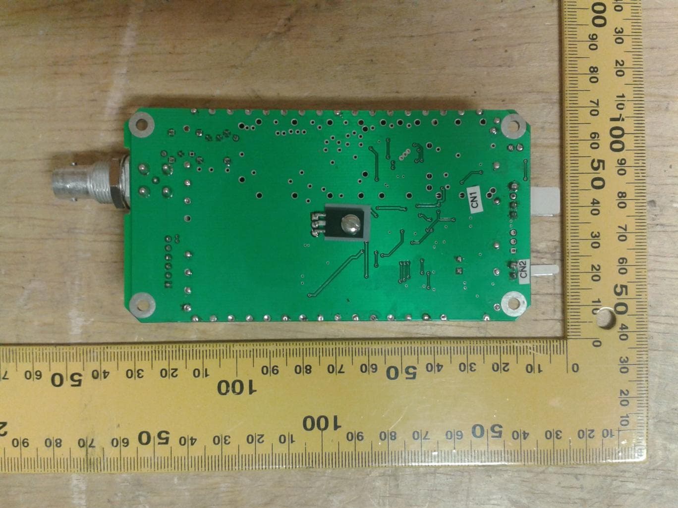
JRNUSA1WTX
Nov 17, 20141 Watt Synthesized UHF Transmitter
Equipment Class
TNB - Licensed Non-Broadcast Station Transmitter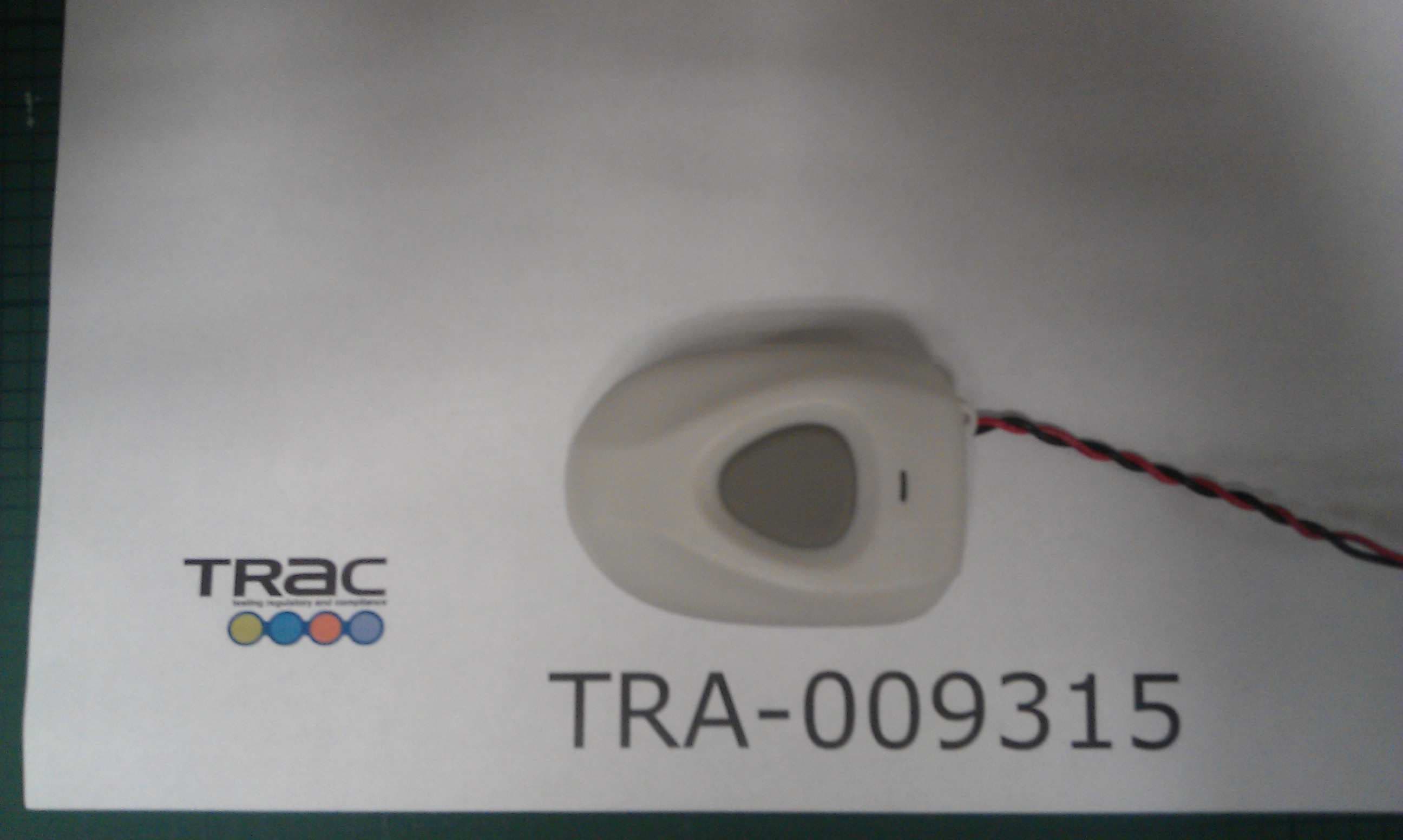
JRNUSAPENLINK
Feb 04, 2013MPA3 Pendant Alarm Transmitter
Equipment Class
TNT - Licensed Non-Broadcast Transmitter Worn on Body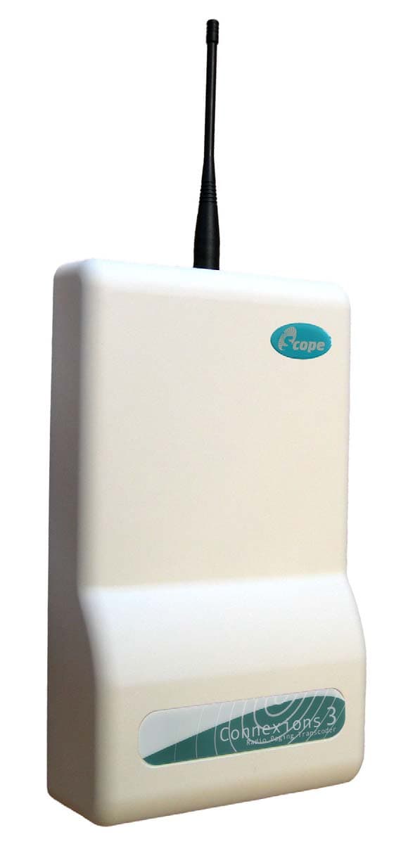
JRNUSAECOLINK
Jan 31, 2007UHF Paging System
Equipment Class
TNB - Licensed Non-Broadcast Station Transmitter
JRNMOBILINK
Jan 03, 2002Paging Transmitter
Equipment Class
TNT - Licensed Non-Broadcast Transmitter Worn on BodyJRNUSAAMP1-10
Apr 28, 1997Rated Input Power .465 Watts
Equipment Class
TNB - Licensed Non-Broadcast Station Transmitter