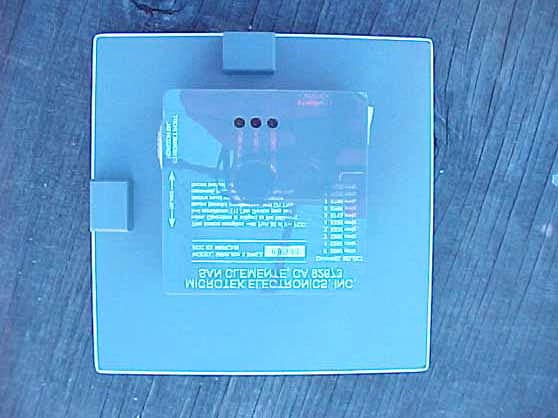
JRR24TA-900TICVideo Transmitter
Microtek Electronics Inc
Click to zoom
Application Details
- Equipment Class
- TNB - Licensed Non-Broadcast Station Transmitter
- Date of Grant
- Feb 26, 2007
- Application Purpose
- Original Equipment
- Date of Application
- Feb 25, 2007
- Equipment Note
- Video Transmitter
- Frequency Range
- 2474.00000000 - 2474.00000000
- Company
- Microtek Electronics Inc
- Country
- United States
Documents & Files
Document Text
Text extracted from the exhibit documents filed with the FCC. Open a document above to read the original.
Users Manual
Microtek Electronics, Inc. 25691 Atlantic Ocean Drive, Suite B3, Lake Forest, CA 92630 Information Hotline 888-36-MICRO Jan 2000 M INI L INK 24TA-900TIC Video Transmitter The Minilink transmitter system allows transmissions of wireless signals from a remote location to a monitor or a VCR. The system uses advanced micro circuitry for a compact miniature design, all packaged within a rugged metal case. The Minilink transmitter’s output frequency is user selectable to one of two frequencies on the 2400-MHz band. FCC NOTICE This equipment has been tested and found to comply with the limits of a Class B device, pursuant to PART 90 of the FCC Rules. These limits are designed to provide reasonable protection against harmful interference. This equipment generates, uses and can radiate radio frequency energy, and, if not installed and used in accordance with the instructions, may cause harmful interference to radio communications. However, there is no guarantee that interference will not occur in a particular installation. If this equipment does cause harmful interference to radio or television reception, which can be determined by turning the equipment off and on, the user is encouraged to try to correct the interference by one or more of the following measures: • Reorient or relocate the receiving antenna. • Increase the separation between the equipment and receiver. • Connect the equipment into an outlet on a circuit different from that to which the receiver is connected. • Consult your dealer or an experienced radio/TV technician for help. Any changes or modifications not expressly approved by the manufacturer could void the user’s authority to operate the equipment. M ICROTEK L IMITED W ARRANTY Microtek Electronics extends the following LIMITED WARRANTY to the original owner/purchaser of this product: 1) If, within one year after date of initial sale, this product, or any part or p ortion thereof, shall prove upon examination by MICROTEK, to be defective in material or workmanship, MICROTEK will repair or replacesuch part or portion at MICROTEK’s option. The warranty period on therepaired or replaced part or portion of this product shall be limited to theunexpired term of the original warranty. The buyer shall be responsible for all shipping and transportation of the product to MICROTEK for an y performance under this warranty. 2) Conditions and Exceptions: a) Any accident to this product, any misuse or abuse, alternation, use in modified form, or any attempt to repair this product shall void this warranty. These conditions to the warranty include, but are no t limited to, incorrect power connections, physical damage due tomechanical shock, exposure to moisture, and circuit modification. b) SHOULD THIS PRODUCT PROVE DEFECTIVE FOLLOWING PURCHASE, THE BUYER, NOT THE MANUFACTURER,DISTRIBUTOR, OR RETAILER, ASSUMES THE ENTIRE COSTOF ALL SERVICING OR REPAIR, EXCEPT AS OTHERWISEPROVIDED BY THE TERMS OF THIS WARRANTY. c) FOR BREACH OF ANY WRITTEN OR IMPLIED WARRANTY ON THIS PRODUCT, THE BUYER IS LIMITED TO THEFOLLOWING DAMAGES. (1) THE COST OF LABOR TOREPAIR OR REPLACE DEFECTIVE PARTS OR PORTIONS OFTHIS PRODUCT, AND (2) THE COST OF THE REPAIRED O R REPLACE PARTS OR PORTIONS OF THIS PRODUCT. d) N O OTHER EXPRESSED OR IMPLIED WARRANTIES HAVE BEEN MADE OR WILL BE MADE ON BEHALF OF MICROTE K WITH RESPECT TO THE SALE, REPAIR, INSTALLATION,OPERATION, OR REPLACEMENT OR THIS PRODUCT.MICROTEK DISCLAIM ANY IMPLIED WARRANTY OFMERCHANTABILITY OF THIS PRODUCT OR ITS FITNESSFOR ANY PURPOSE, AND THE BUYER AGREES THAT THIS PRODUCT IS SOLD “AS IS” AND THAT THE ENTIRE RISK OFQUALITY AND PERFORMANCE OF THIS PRODUCT IS WITHTHE BUYER, EXCEPT AS OTHERWISE PROVIDED BY THETERMS OF THIS WARRANTY. e) Some states/jurisdictions do not allow exclusions or limitations o f incidental or consequential damages, or limitations on how long a n implied warranty lasts, so the above exclusions or limitations may notapply to you. 3) Contact your dealer regarding return authorization for out of warrant y repairs and any further product information. Operation The Minilink video transmitter is designed to be used in conjunction with a compatible receiver. Refer to the instructions accompanying your receiver for proper installation of that unit. LOCATION: • The Minilink has been designed to be mounted against a flat surface for support and stability. ( Note: The location selected for mounting the Minilink should be protected form immersion in water unless the Minilink is enclosed in a watertight enclosure, and should have a moderate shock protection.) POWER: • The Minilink is powered by a 8.5-13.8VDC power supply connected through the 4-pin connector harness protruding from the side of the Minilink case. Pin 1) Video In. Pin 2) Video Ground Pin 3) Power Ground Pin 4) Power Positive SETUP & OPERATION: • Connect Power and video. • Select Frequency MAINTENANCE Your Microtek Electronics product is an example of superior design and craftsmanship. The following suggestions will help you care for the systems so that you can enjoy it for years. • Keep the product dry. If it does get wet, wipe it dry immediately. Liquids might contain minerals than can corrode the electronic circuits. • Use and store the system only in normal room temperature environments. High temperatures can shorten the life of electronic devices, damage batteries, and distort or melt plastic parts. • Handle the system gently and carefully. Dropping it can damage the circuit board and case. Moving or tampering with the system’s internal components can cause a malfunction and invalidate the system’s warranty and void your FCC authorization to operate it. If your system is not performing, as it should, contact your dealer. They can assist you and arrange for service, if needed. SPECIFICATIONS 24TA-900TIC* Dimensions: 2.25”x1.5”x .43” Weight: 1.7 oz. Power Requirements: 8.5-13.8 VDC @ 380 mA Operating Temperature: -10 ° F to 180 ° F Case Temperature Power Output: +30.4 dBm (1.096 W) …
Text truncated - open the document above for the full version.
RF Exposure Info
MPE Calculations For RF Exposure Requirements Video Transmitter Model: 24TA-900TIC Page 1 of 1 MAXIMUM PERMISSIBLE EXPOSURE FOR SUBPART C 2.4 GHz BAND Calculations Power density at the specific separation: S = PG/(4R 2 π) S = (1099 * 1.585) / (4 * 20 2 * π) S = 0.34654 mW/cm 2 (at 1 cm) Limit = 1 mW/cm 2 where S = Maximum power density (mW/cm 2 ) P = Power input to the antenna (mW) – (30.41) dBm G = Numeric power gain of the antenna R = distance to the center of the radiation of the antenna (20 cm = limit for MPE) The maximum permissible exposure (MPE) for the general population is 1 mW/cm 2 . The power density at 1 cm does not exceed the 1 mW/cm 2 . Therefore, the exposure condition is compliant with FCC rules. The numeric gain (G) of the antenna with a gain specified in dB is determined by: G = Log -1 (dB antenna gain/10) G = Log -1 (2 dBi/10) G = 1.585
Test Report
Report Number: B70131X1 FCC Part 90 and FCC Part 15 Class B Test Report Video Transmitter Model: 24TA-900TIC 114 OLINDA DRIVE, BREA, CALIFORNIA 92823 PHONE: (714) 579-0500 FAX: (714) 579-1850 Page 1 of 21 FCC PART 90 and PART 15, SUBPART B TEST REPORT for VIDEO TRANSMITTER Model: 24TA-900TIC Prepared for MICROTEK ELECTRONICS, INC. 25691 ATLANTIC OCEAN DRIVE, SUITE B3 LAKE FOREST, CALIFORNIA 92630 Prepared by:_____________________ KYLE FUJIMOTO Approved by:____________________ MICHAEL CHRISTENSEN COMPATIBLE ELECTRONICS INC. 114 OLINDA DRIVE BREA, CALIFORNIA 92823 (714) 579-0500 DATE: FEBRUARY 6, 2007 REPORT APPENDICES TOTAL BODY A B C D E PAGES 21 2 2 2 15 22 64 This report shall not be reproduced except in full, without the written approval of Compatible Electronics. Report Number: B70131X1 FCC Part 90 and FCC Part 15 Class B Test Report Video Transmitter Model: 24TA-900TIC 114 OLINDA DRIVE, BREA, CALIFORNIA 92823 PHONE: (714) 579-0500 FAX: (714) 579-1850 Page 2 of 21 TABLE OF CONTENTS Section / Title PAGE GENERAL REPORT SUMMARY 4 SUMMARY OF TEST RESULTS 5 1. PURPOSE 6 2. ADMINISTRATIVE DATA 7 2.1 Location of Testing 7 2.2 Traceability Statement 7 2.3 Cognizant Personnel 7 2.4 Date Test Sample was Received 7 2.5 Disposition of the Test Sample 7 2.6 Abbreviations and Acronyms 7 3. APPLICABLE DOCUMENTS 8 4. DESCRIPTION OF TEST CONFIGURATION 9 4.1 Description of Test Configuration - EMI 9 4.1.1 Cable Construction and Termination 10 5. LISTS OF EUT, ACCESSORIES AND TEST EQUIPMENT 11 5.1 EUT and Accessory List 11 5.2 EMI Test Equipment 12 6. TEST SITE DESCRIPTION 14 6.1 Test Facility Description 14 6.2 EUT Mounting, Bonding and Grounding 14 7. TEST PROCEDURES 15 7.1 Radiated Emissions (Spurious and Harmonics) Test for Part 90 15 7.2 Radiated Emissions (Spurious and Harmonics) Test for Part 90 (continued) 16 7.3 Radiated Emissions (Spurious and Harmonics) Limit for Part 90 17 7.4 RF Power Output of the EUT 18 7.5 Modulation Characteristics – Audio Frequency Response 18 7.6 Modulation Characteristics – Audio Frequency Response 18 7.7 Occupied Bandwidth for the EUT 18 7.8 Spurious Emissions at the Antenna Terminal 19 7.9 Frequency Stability 19 8. EMISSION DESIGNATOR 20 9. CONCLUSIONS 21 Report Number: B70131X1 FCC Part 90 and FCC Part 15 Class B Test Report Video Transmitter Model: 24TA-900TIC 114 OLINDA DRIVE, BREA, CALIFORNIA 92823 PHONE: (714) 579-0500 FAX: (714) 579-1850 Page 3 of 21 LIST OF APPENDICES APPENDIX TITLE A Laboratory Recognitions B Modifications to the EUT C Additional Models Covered Under This Report D Diagrams, Charts and Photos • Test Setup Diagrams • Radiated Emissions Photos • Antenna and Effective Gain Factors E Data Sheets LIST OF FIGURES FIGURE TITLE 1 Plot Map And Layout of Test Site Report Number: B70131X1 FCC Part 90 and FCC Part 15 Class B Test Report Video Transmitter Model: 24TA-900TIC 114 OLINDA DRIVE, BREA, CALIFORNIA 92823 PHONE: (714) 579-0500 FAX: (714) 579-1850 Page 4 of 21 GENERAL REPORT SUMMARY This electromagnetic emission test report is generated by Compatible Electronics Inc., which is an independent testing and consulting firm. The test report is based on testing performed by Compatible Electronics personnel according to the measurement procedures described in the test specifications given below and in the "Test Procedures" section of this report. The measurement data and conclusions appearing herein relate only to the sample tested and this report may not be reproduced without the written permission of Compatible Electronics, unless done so in full. This report must not be used to claim product endorsement by NVLAP or any other agency of the U.S. Government. Device Tested: Video Transmitter Model: 24TA-900TIC S/N: N/A Product Description: See Expository Statement. Modifications: The EUT was not modified during the testing. Emission Designator 16MOF3F (see section 8 of this test report) Manufacturer: Microtek Electronics, Inc. 25691 Atlantic Ocean Drive Lake Forest, California 92630 Test Dates: January 29, 30, and 31, 2007 Test Specifications: EMI requirements CFR Title 47, Part 90, Subpart I; and CFR Title 47, Part 15, Subpart B Test Procedure: ANSI C63.4 and ANSI/TIA-603-C Test Deviations: The test procedure was not deviated from during the testing. Report Number: B70131X1 FCC Part 90 and FCC Part 15 Class B Test Report Video Transmitter Model: 24TA-900TIC 114 OLINDA DRIVE, BREA, CALIFORNIA 92823 PHONE: (714) 579-0500 FAX: (714) 579-1850 Page 5 of 21 SUMMARY OF TEST RESULTS TEST DESCRIPTION RESULTS 1 Conducted RF Emissions, 150 kHz - 30 MHz This test was not performed because the EUT operates on battery power only and cannot be plugged into the AC public mains. 2 RF Power Output of the EUT Complies with the limits of CFR Title 47, Part 90, Section 90.205 (n) 3 Modulation Characteristics – Audio Frequency Response This test was not performed because this test is not applicable to the EUT 4 Modulation Characteristics – Modulation Limiting Response This test was not performed because this test is not applicable to the EUT 5 Occupied Bandwidth for the EUT Complies with the limits of CFR Title 47, Part 90 Section 90.210 (b) 6 Radiated RF Emissions on the Digital Portion 30 MHz – 25000 MHz Complies with the Class B limits of CFR Title 47, Part 15, Subpart B 7 Radiated Spurious Emissions on the Transmitter portion – 10 kHz to 25000 MHz Complies with the limits of CFR Title 47, Part 90 Section 90.210 (b) 8 Spurious Emissions at the Antenna Terminal Complies with the limits of CFR Title 47, Part 90 Section 90.210 (b) 9 Frequency Stability Complies with the limits of CFR Title 47, Part 90 Section 90.213 Report Number: B70131X1 FCC Part 90 and FCC Part 15 Class B Test Report Video Transmitter Model: 24TA-900TIC 114 OLINDA DRIVE, BREA, CALIFORNIA 92823 PHONE: (714) 579-0500 FAX: (714) 579-1850 Page 6 of 21 1. PURPOSE This document is a qualification test report based on the Electromagnetic Interference (EMI) tests performed on the Video Transmitter Model: 24TA-90…
Text truncated - open the document above for the full version.
Contact Information
Applicant
Michael L. Henkoski(VP, Engineering)
Technical Contact
Compatable ElectronicsKyle Fujimoto
[email protected]714 5790500
114 Olinda Drive · Brea · United States
Test Firm
Compatible Electronics, Inc.Michael Christensen
Technical Specifications
| # | Rule Parts | Frequency Range | Power Output | Emission | Tolerance |
|---|---|---|---|---|---|
| 2 | 9 | 2.47 GHz - 2.47 GHz | 1.093 W | 16M0F3F | 19.8 ppm |
Other Applications from Microtek Electronics Inc
JRRWES
Jun 14, 2005MiniLink Wireless Ethernet System
Equipment Class
DTS - Digital Transmission System
JRR-PHIL2-11
Mar 02, 2003Video Transmitter
Equipment Class
TNB - Licensed Non-Broadcast Station Transmitter
JRR-1JOHN4-14
Feb 23, 2003Video Transmitter
Equipment Class
TNB - Licensed Non-Broadcast Station Transmitter
JRR-PHL4-13
Nov 11, 2002Video/Audio Transmitter Module
Equipment Class
DXX - Part 15 Low Power Communication Device Transmitter
JRR-PS37-4
Aug 06, 2002Video and Audio Transmitter
Equipment Class
DXX - Part 15 Low Power Communication Device Transmitter