JRRWESMiniLink Wireless Ethernet System
Microtek Electronics Inc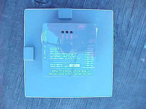
Click to zoom
Application Details
- Equipment Class
- DTS - Digital Transmission System
- Date of Grant
- Jun 14, 2005
- Application Purpose
- Original Equipment
- Date of Application
- Jun 14, 2005
- Equipment Note
- MiniLink Wireless Ethernet System
- Frequency Range
- 5745.00000000 - 5825.00000000
- Company
- Microtek Electronics Inc
- Country
- United States
Documents & Files
Document Text
Text extracted from the exhibit documents filed with the FCC. Open a document above to read the original.
Users Manual
OPERATIONS MANUAL MiniLink® Wireless Ethernet System MicroTek Electronics, Inc. 25691 Atlantic Ocean Drive, Suite B-3; Lake Forest, CA 92630 Information Hotline 888-36-MICRO www.microtekelectronics.com IMPORTANT SAFETY INSTRUCTION For your protection, please read and observe all safety instructions before operating this system and keep this sheet and any additional instructions for future reference. INSTALLATION & USE OBSERVE WARNINGS: All warnings in the operating instructions should be carefully followed. WATER AND MOISTURE: The Wireless Ethernet Modules used in this system are weatherproof provided they are installed correctly. The Power Injection Modules used in this system are NOT weatherproof. None of the modules in this system are waterproof and should never be submerged. Severe electrical shock, personal injury or damage to the equipment may result. POWER SOURCE: Connect the equipment to a power source only of the type described on the operating instructions or as marked on the equipment. ATTACHMENTS: Use only MicroTek supplied or recommended Power Injection Modules, Power Supplies, CAT5 Cables and weather seals and plugs. WHEN NOT IN USE: Unplug the power if the equipment is left unattended or unused for long periods of time or during lightning storms REPLACEMENT PARTS: When replacement parts are required, use only replacement parts specified by MicroTek Electronics, Inc. Unauthorized substitutions may result in damage to the system and will void the warranty. FCC-Required Information Federal Communications Commission Radio Frequency Interference Statement for Class A Digital Devices This equipment has been tested and found to comply with the limits for a Class A digital device, pursuant to Part 15 of the FCC Rules. These limits are designed to provide reasonable protection against harmful interference when the equipment is operated in a commercial environment. This equipment generates, uses, and can radiate radio frequency energy and, if not installed and used in accordance with the instruction manual, may cause harmful interference to radio frequencies. Operation of this equipment in a residential area is likely to cause harmful interference in which case the user will be required to correct the interference at his own expense. This equipment is designed to be professionally installed exclusively for fixed point-to-point applications. These products must be controlled due to radio frequency power output levels emitted with special consideration given to antenna placement as it relates to human exposure. Compliance is the responsibility of the installer and user. Radio Frequency Interface Statement This equipment has been tested and found to comply with the limits for an intentional radiator, pursuant to Part 15, Subpart C of the FCC Rules. This equipment generates, uses, and can radiate radio frequency energy. If not installed and used in accordance with the instructions, it may cause interference to radio communications. The limits are designed to provide reasonable protection against such interference in a residential situation. However, there is no guarantee that interference will not occur in a particular installation. If this equipment does cause interference to radio or television reception, which can be determined by turning the equipment on and off, the user is encouraged to try to correct the interference by one or more of the following measures: • Reorient or relocate the receiving antenna of the affected radio or television. • Increase the separation between the equipment and the affected receiver. • Connect the equipment and the affected receiver to power outlets on separate circuits. • Consult the dealer or an experienced radio/TV technician for help. Shielded cables must be used with this unit to ensure compliance with Class A FCC limits. Changes or modifications to this unit not expressly approved by the party responsible for compliance could void the users authority to operate the equipment. Changes or modifications not expressly approved by MicroTek could void the users authority to operate the equipment. - ( i ) - FCC Output Power Restrictions The FCC does not require licensing to implement this device. License-free operation in the industrial, scientific, and medical band is documented in FCC Rules Part 15.247. It is the responsibility of the individuals designing and implementing the radio system to assure compliance with any pertinent FCC Rules and Regulations. This device must be professionally installed. Exposure to Radio Frequency Fields The Minilink 5.8WES is designed to operate at 5.8 GHz with up to 20 Watts EIRP maximum transmit power. This level of RF energy is above the Maximum Permissible Exposure (MPE) levels specified in FCC OET65:97-01. The following precautions must be taken during installation of this equipment: • The installed antenna must not be located in a manner that allows exposure of the general population to the direct beam path of the antenna at a distance less than 1 Meter. Installation on towers, masts, or rooftops not accessible to the general population is recommended; or • Mount the antenna in a manner that prevents any personnel from entering the area within 1 Meter from the front of the antenna. • It is recommended that the installer place radio frequency hazard warnings signs on the barrier that prevents access to the antenna. • During installation and alignment of the antenna, do not stand in front of the antenna assembly. • During installation and alignment of the antenna, do not handle or touch the front of the antenna. These simple precautions must be taken to prevent general population and installation personnel from exposure to RF energy in excess of specified MPE levels. Industry Canada Restrictions This device is in compliance with the applicable sections of the Industry Canada RSS-210 Spectrum Management and Telecommunications Radio Standard Specification that governs Low Power License-Exempt Radiocommunication Devic…
Text truncated - open the document above for the full version.
Cover Letter(s)
25691 ATLANTIC OCEAN DRIVE, SUITE B3, LAKE FOREST, CA 92630 PHONE: (888) 366-4276 FACSIMILE: (949) 297-4933 www.microtekelectronics.com June 14, 2005 Federal Communications Commission 7435 Oakland Mills Road Columbia, MD 21046 Subject: Professional Installation Requirement Gentlemen: With regard to the MiniLink Wireless Ethernet System (WES), the following three points apply: a) Marketing – These products are sold through an authorized network of security distributors, integrators and dealers only. They are not available through retail outlets or mail order. b) Professional Installation – These products require professional installation and must be controlled due to radio frequency power output levels emitted with special consideration given to antenna placement as it relates to human exposure. c) Application – Due to the extended range capability of these products, they are intended for use in industrial/commercial environments only. They are not intended for use by the general public in consumer applications. If you have any questions, please contact us at (949) 297-4930. Sincerely, Steve Kuntz Vice President Sales & Marketing MicroTek Electronics, Inc.
Cover Letter(s)
114 OLINDA DRIVE • •• • BREA, CALIFORNIA 92823 • •• • (714) 579-0500 • •• • FAX (714) 579-1850 May 20, 2005 FCC-ID: JRRWES 1) The block diagram should show the frequencies of all oscillators in the TX device (CFR 2.1033(a)(5)), unless this portion of the device is an OEM part from a different manufacturer. Please provide either the block diagram for the TX portion, or alternatively provide a parts list that shows that this part is provided by another manufacturer. Please update the list of confidential exhibits if necessary. Response: Uploaded is the block diagram for the Tx portion. 2) The schematics do not include the RF mini-PCI card. Note that a schematic for the TX portion of the device is required as specified 2.1033(b)(5) for the RF section. Please provide either a schematic for the mini-PCI card or as an alternative, you may provide a parts list that lists that shows that this part is provided by another manufacturer. Please provide either a schematic or parts list as specified. If necessary, please update the confidentiality letter to include the parts list. Response: Uploaded will be the schematics for the Tx portion. 3) 2 antennas are integrated, while one is external. Please provide information regarding 15.203 for the external antenna. Response: The dish (external) antenna uses a passive reflector with no electrical connection. 4) Maximum gain of antennas appears to be 24 dBi, while MPE uses a higher number. Note that all information in the application must be consistent. Please review, explain, and correct as necessary. Response: The MPE Calculations has been revised to show 24 dBi, which is what the maximum gain of the dish antenna is. 5) It appears that one of the emails correct the antenna gain of the larger panel antenna. Kindly update the reports for the correct gain of the antenna. Response: The UNII Report has been revised to show the correct gain for the larger panel antenna, which is 12.2 dBi. The E-mail does NOT correct any gains for the DTS portion. 6) Peak to average measurements made for both reports show as much as 30 dB apart (for the DTS portion - Dish Antenna, Bandedge for UNII band - page 74). This delta is considered very excessive and suggests that the device may have been transmitting with a duty cycle associated with the carrier instead of the carrier having a 100% on time during testing (which is specified by the recommended test procedures from the FCC). Additionally, please note that certain plots (i.e. bandwidth plots) support that the carrier was not on 100% during test and did have an associated duty cycle associated with the modulation. Note that the use of VBW = 10 Hz is only considered valid if the duty cycle associated with any duty cycle is VBW > 1/Ton time. You may need to provide information regarding carrier Ton vs. Toff time and increase the VBW to be considered valid. Please review, correct, or remeasure as necessary as it appears that average measurement may not have been correctly taken and if so, this can significantly affect the results reported. Response: This is still being discussed with the Client. We are sending these responses so that we can clear up the other issues except this one so we know how to proceed with this issue. 114 OLINDA DRIVE • •• • BREA, CALIFORNIA 92823 • •• • (714) 579-0500 • •• • FAX (714) 579-1850 May 20, 2005 FCC-ID: JRRWES 7) Given the high level of the digital emissions meeting the Class A limits, please explain what precautions were taken to measure Transmitter emissions < 1 GHz to meet Class B levels given the dynamic range of the digital device emissions exceeds class B levels. Response: Any emission that was tested to Class A was done with the transmitter turned off. The transmitter was then turned on and the emission investigated again to insure the emission did not go higher. 8) The application mentions different power levels for different antennas, but it does not appear to address or document what these levels are with what antennas. Please explain. Response: The 731 form only shows the highest power allowed. Let us know if you want us to revise the 731 form to show the highest power for each individual antenna. 9) Operation in the 5725-5850 MHz bands does not appear to require power reduction (15.247(b)(4)(ii). However, bandedge emissions within the DTS report appear to have been performed at 2 power level. Was reduction necessary for this band? If so, please explain. Response: The bandedge emissions did not require a reduction of power for the DTS. These bandedges were performed radiated with each antenna (Small Panel, Medium Panel, and Dish Antenna) for both Normal and Turbo Modes. 10) It is not certain that receiver emissions were measured up to 3 times the fundamental an/or local oscillator (RSS-210, section 7). Tables in both DTS and UNII do not clearly identify frequency bands investigated. Please provide or explain where this information may be found. Response: The Receive Mode was checked from 30 MHz to 40 GHz. The data sheets have been revised to show the frequency range and that they were checked in both vertical and horizontal polarization. 11) Please explain compliance to 15.407(c). Response: This same question was asked of the OEM manufacturer of the RF module (Later granted FCC ID, NKRCM9) in a letter from ATCB dated May 27, 2004. The Microtek WES design uses the same firmware code for implementation of this requirement. Answer: "Data transmission is always initiated by software, which is then passed through the MAC, through the digital and analog baseband, and finally to the RF chip. Several special packets(ACKs, CTS, PSPoll, etc...) are initiated by the MAC. These are the only ways by which the digital baseband portion will turn on the RF transmitter, which it then turns off at the end of the packet. Therefore, the transmitter will be on only while one of the aforementioned packets is being transmitted." 114 OLINDA DRIVE • •• • BREA, CALIFORNIA 92823 • •• • (714) 579-0500 • •• •…
Text truncated - open the document above for the full version.
Cover Letter(s)
114 OLINDA DRIVE • •• • BREA, CALIFORNIA 92823 • •• • (714) 579-0500 • •• • FAX (714) 579-1850 June 6, 2005 FCC-ID: JRRWES Please Note: All of the other questions have already been responded to on May 20, 2005. 6) Peak to average measurements made for both reports show as much as 30 dB apart (for the DTS portion - Dish Antenna, Bandedge for UNII band - page 74). This delta is considered very excessive and suggests that the device may have been transmitting with a duty cycle associated with the carrier instead of the carrier having a 100% on time during testing (which is specified by the recommended test procedures from the FCC). Additionally, please note that certain plots (i.e. bandwidth plots) support that the carrier was not on 100% during test and did have an associated duty cycle associated with the modulation. Note that the use of VBW = 10 Hz is only considered valid if the duty cycle associated with any duty cycle is VBW > 1/Ton time. You may need to provide information regarding carrier Ton vs. Toff time and increase the VBW to be considered valid. Please review, correct, or remeasure as necessary as it appears that average measurement may not have been correctly taken and if so, this can significantly affect the results reported. Response: This portion of the test has been redone so that VBW > 1/Ton time. This means the VBW was 30 kHz for Normal Mode, and the VBW was 50 kHz for Turbo Mode. Please see the Revised Test Reports. To allow the EUT to pass using these revised test procedures, the client will be removing the low channel (5260 MHz) and moving the Turbo Mode channel from 5280 MHz to 5300 MHz. Please see the revised Label, 731 Form, RSP-100 Form, and the Owners Manual that reflect these changes.
Cover Letter(s)
114 OLINDA DRIVE • •• • BREA, CALIFORNIA 92823 • •• • (714) 579-0500 • •• • FAX (714) 579-1850 June 14, 2005 FCC-ID: JRRWES 1) The internal TX appears to be capable of transmitting on 2.4 GHz and 5150 – 5250 MHz bands. Please explain how the device is compliant to 15.15 of the rules given this capability. Response: Only the 5250 MHz to 5350 MHz and 5825 MHz to 5850 MHz bands can be used by the user. This is because the 10 position switch only allows the user to select these bands. Please see the label attached. Also, each channel has been verified with an EMI Receiver to insure that none of the positions on the switch cause the unit to transmit in the 2.4 GHz or the 5150 MHz to 5250 MHz band. Also, the software will not support frequency selection outside of the band that were tested. 2) Regarding your response to item 12 & 13, please explain if the users are provided any information on how to change jumper settings, and if the manufacturer expects the end user to be able to adjust these settings. Response: The manufacturer does NOT expect the end user to be able to adjust these settings. The jumper is set depending on what type of antenna the customer wants. So if the customer purchases a unit with a small antenna, both jumper positions will be open. If the customer purchases a unit with a patch antenna, the “17.7 dBi” (per the PCB layout on the unit) jumper will be shorted. If the customer purchases a unit with a dish antenna, the “25.5 dBi” (per the PCB layout on the unit) jumper will be shorted. The jumpers are NOT readily accessible nor are intended to be accessible to the user. The unit is sealed and the label covers the mounting screws. 3) Your response to item 7 mentions you investigated again to insure the emissions did not go higher than class A with the radio turned on. The concern here is that the limits for TX spurious are equivalent to Class B levels. In the < 1 GHz band, how is compliance to Class B levels for TX spurious determined given the digital devices emissions exceeded Class B levels. Note that the FCC does not simply accept that a Class A digital device + TX spurious are < Class A levels. Any levels exceeding class B thresholds must be determined not to be from the TX portion of the device. This sometimes creates rather complicated or difficult test methods in order to insure proper compliance of TX spurious. Please explain how this was done in this case. Response: The EUT was re-verified with the transmitter on. Any reading that was over the Class B limit was then re-checked by turning off the transmitter. The transmitter portion of the EUT is then turned off by disconnecting the accessory unit that is used to generate throughput with the EUT. This then causes the green LED “signal level” to turn off on the EUT. An EMI Receiver is then used to verify that the transmitter has stopped transmitting. Next, the readings that were over the Class B limit with the transmitter still on were re-verified again to see they did not go lower or disappear with the transmitter off (which would indicate those emissions came or where being contributed to by the transmitter portion). Then, those readings were measured to the Class A limits. 114 OLINDA DRIVE • •• • BREA, CALIFORNIA 92823 • •• • (714) 579-0500 • •• • FAX (714) 579-1850 4) Regarding item 8, the test report and/or application should adequately document the power levels utilized for each antenna, especially when power reductions are necessary for various configurations. This also goes for channel selection as well. Please provide a table/matrix as necessary to adequately document each antenna configuration, and channel/power settings for each configuration as well. Additionally, the manual states the system must be professionally installed. Does it need to be professionally installed for channel or power setting reasons? Does the user have access to power settings after installation? Please provide information as necessary to explain compliance to 15.15 given power selections. Additionally, how is compliance to 15.15 ensured for the final device given the different power levels necessary for each antenna. Response: The customer is given a unit based on what type of antenna he or she wants. In other words, the customer will not be able to change the antenna. The power levels are controlled by what jumper is shorted. For the small antenna, no jumpers are shorted, for the patch antenna, the “17.7 dBi” jumper is shorted, for the dish antenna, the “25.5 dBi” jumper is shorted. Again, the customer will not have any access to the jumpers. Please note that the power level changes are only for the 5250 MHz to 5350 MHz band and not for the upper 5 GHz band. The upper 5 GHz band has only 1 power setting used for all antennas (in other words the jumper settings do not cause the power to change in the upper 5 GHz band). 114 OLINDA DRIVE • •• • BREA, CALIFORNIA 92823 • •• • (714) 579-0500 • •• • FAX (714) 579-1850 5) Regarding your response to 12 & 13, is this explained to the user? The label on the back of the device suggests they can change the channel to other listed on the label. Response: The user can change the channel using the rotary switch on the unit. Please note that if the user tries to use the 5150 MHz to 5250 MHz band for the dish antenna, the software will not allow this and will automatically set the unit for 5745 MHz. Also, positions 0, 1, and 2 on the switch will cause the unit to go to 5280 MHz for the small and dish antennas. Let us know if we need to explain in the owner’s manual that if a user goes to a frequency in the 5150 MHz to 5250 MHz band for the dish antenna, that the unit will default to 5745 MHz. 6) If the installer is capable of adjusting power for certain antenna installations, does the installer manual adequately explain this to the installer. If so, then a copy of the installer manual should also be provided. Response: The installer is NOT capable of adjusting the power. The power is pre determined…
Text truncated - open the document above for the full version.
Operational Description
Kyle, Each of the antenna systems used with the three versions of the 5.8WES product are manufactured by MicroTek Electronics, Inc. Single patch (small) gain is: 7.8 dBi @ 5.8 gHz and 7.5 dBi @ 5.3 gHz Planar patch array (medium) gain is: 16.7 dBi @ 5.8 gHz and 14.6 dBi @ 5.3 gHz 18" dish (large) gain is: 24 dBi @ 5.8 & 5.3 gHz Mike From: "Mike Henkoski" <[email protected]> To: [email protected] Date: 04/13/2005 03:57 PM Subject: 5.8WES antenna gains Page 1 of 1WorldClient 4/19/2005https://www.celectronics.com:3001/WorldClient.dll?Session=EHVEEXP&View=Message...
Operational Description
Kyle, I retested all the antenna's yesterday to be sure of the gains and need to revise only one. The medium gain patch is 12.2 dbi @ 5.3 ghz instead of the 14.6 dBi I indicated in a previous email. I had mistakenly gathered that data at 5.6 gHz. Thanks, Mike From: "Mike Henkoski" <[email protected]> To: [email protected] Date: 04/15/2005 10:15 AM Subject: Revised patch antenna gain Page 1 of 1WorldClient 4/19/2005https://www.celectronics.com:3001/WorldClient.dll?Session=EHVEEXP&View=Message...
RF Exposure Info
MPE Calculations Systems operating under the provision of 47 CFR 1.1307(b)(1) shall be operated in a manner that ensures that the public is not exposed to radio frequency energy levels in excess of the FCC guidelines. The EUT will only be used with a separation of 1 meter or greater between the antenna and the body of the user or nearby persons and can therefore be considered a mobile transmitter per 47 CFR 2.1091(b). The MPE calculation for this exposure is shown below. Power density at the specific separation: S = PG/(4R 2 π) S = (269.77 x 251.19) / (4 x 100 2 x π ) S = 0.53925 mW/ cm 2 Where S = Maximum power density (mW/cm 2 ) P = Power input to the antenna (mW). G = Numeric power gain of the antenna – worst case R = Distance to the center of the radiation of the antenna (100 cm = distance user should be away from the antenna per the owner’s manual warning) The maximum permissible exposure (MPE) for the general population is 1mW/cm 2. The power density at 1 meter does not exceed the 1mW/ cm 2 limit. Therefore, the exposure condition is compliant with FCC rules. Estimated safe separation: R = √PG/4π R = √(269.77 x 251.19) / 4π R = 73.43 cm Where P = Power input to the antenna (mW). G = Numeric power gain of the antenna – worst case R = The safe estimated separation that the user must maintain from the antenna (cm) The numeric gain (G) of the antenna with a gain specified in dB is determined by: G = Log -1 (antenna gain in dBi/10) G = Log -1 (24/10) G = 251.19
Test Report
Report Number: B50401D1 FCC Part 15 Subpart B and FCC Section 15.247 Test Report Minilink Wireless Ethernet System Model: Minilink 5.8WES Brea Division 114 Olinda Drive Brea, CA 92823 (714) 579-0500 Agoura Division 2337 Troutdale Drive Agoura, CA 91301 (818) 597-0600 Silverado Division 19121 El Toro Road Silverado, CA 92676 (949) 589-0700 Lake Forest Division 20621 Pascal Way Lake Forest, CA 92630 (949) 587-0400 Page 1 of 22 FCC PART 15, SUBPART B and C TEST REPORT for MINILINK WIRELESS ETHERNET SYSTEM MODEL: MINILINK 5.8WES Prepared for MICROTEK ELECTRONICS, INC. 25691 ATLANTIC OCEAN DRIVE, SUITE B3 LAKE FOREST, CALIFORNIA 92630 Prepared by:_____________________ KYLE FUJIMOTO Approved by:____________________ MICHAEL CHRISTENSEN COMPATIBLE ELECTRONICS INC. 114 OLINDA DRIVE BREA, CALIFORNIA 92823 (714) 579-0500 DATE: JUNE 3, 2005 REPORT APPENDICES TOTAL BODY A B C D E PAGES 22 2 2 2 25 129 182 This report shall not be reproduced except in full, without the written approval of Compatible Electronics. Report Number: B50401D1 FCC Part 15 Subpart B and FCC Section 15.247 Test Report Minilink Wireless Ethernet System Model: Minilink 5.8WES Brea Division 114 Olinda Drive Brea, CA 92823 (714) 579-0500 Agoura Division 2337 Troutdale Drive Agoura, CA 91301 (818) 597-0600 Silverado Division 19121 El Toro Road Silverado, CA 92676 (949) 589-0700 Lake Forest Division 20621 Pascal Way Lake Forest, CA 92630 (949) 587-0400 Page 2 of 22 TABLE OF CONTENTS Section / Title PAGE GENERAL REPORT SUMMARY 4 SUMMARY OF TEST RESULTS 5 1. PURPOSE 6 2. ADMINISTRATIVE DATA 7 2.1 Location of Testing 7 2.2 Traceability Statement 7 2.3 Cognizant Personnel 7 2.4 Date Test Sample was Received 7 2.5 Disposition of the Test Sample 7 2.6 Abbreviations and Acronyms 7 3. APPLICABLE DOCUMENTS 8 4. DESCRIPTION OF TEST CONFIGURATION 9 4.1 Description of Test Configuration - EMI 9 4.1.1 Cable Construction and Termination 10 5. LISTS OF EUT, ACCESSORIES AND TEST EQUIPMENT 11 5.1 EUT and Accessory List 11 5.2 EMI Test Equipment for Brea Facility – Part 1 12 5.3 EMI Test Equipment for Brea Facility – Part 2 13 6. TEST SITE DESCRIPTION 14 6.1 Test Facility Description 14 6.2 EUT Mounting, Bonding and Grounding 14 7. CHARACTERISTICS OF THE TRANSMITTER 15 7.1 Antenna Gain 15 8. TEST PROCEDURES 16 8.1 RF Emissions 16 8.1.1 Conducted Emissions Test 16 8.1.2 Radiated Emissions (Spurious and Harmonics) Test 17 8.2 6 dB and 20 dB Bandwidth 19 8.3 Peak Output Power 19 8.4 RF Antenna Conducted Test 19 8.5 Spectral Density Output 20 8.6 RF Band Edges 21 9. CONCLUSIONS 22 Report Number: B50401D1 FCC Part 15 Subpart B and FCC Section 15.247 Test Report Minilink Wireless Ethernet System Model: Minilink 5.8WES Brea Division 114 Olinda Drive Brea, CA 92823 (714) 579-0500 Agoura Division 2337 Troutdale Drive Agoura, CA 91301 (818) 597-0600 Silverado Division 19121 El Toro Road Silverado, CA 92676 (949) 589-0700 Lake Forest Division 20621 Pascal Way Lake Forest, CA 92630 (949) 587-0400 Page 3 of 22 LIST OF APPENDICES APPENDIX TITLE A Laboratory Recognitions B Modifications to the EUT C Additional Models Covered Under This Report D Diagrams, Charts, and Photos • Test Setup Diagrams • Radiated and Conducted Emissions Photos • Antenna and Effective Gain Factors E Data Sheets LIST OF FIGURES FIGURE TITLE 1 Conducted Emissions Test Setup 2 Plot Map and Layout of 3 Meter Radiated Site 3 Plot Map and Layout of 10 Meter Radiated Site Report Number: B50401D1 FCC Part 15 Subpart B and FCC Section 15.247 Test Report Minilink Wireless Ethernet System Model: Minilink 5.8WES Brea Division 114 Olinda Drive Brea, CA 92823 (714) 579-0500 Agoura Division 2337 Troutdale Drive Agoura, CA 91301 (818) 597-0600 Silverado Division 19121 El Toro Road Silverado, CA 92676 (949) 589-0700 Lake Forest Division 20621 Pascal Way Lake Forest, CA 92630 (949) 587-0400 Page 4 of 22 GENERAL REPORT SUMMARY This electromagnetic emission test report is generated by Compatible Electronics Inc., which is an independent testing and consulting firm. The test report is based on testing performed by Compatible Electronics personnel according to the measurement procedures described in the test specifications given below and in the "Test Procedures" section of this report. The measurement data and conclusions appearing herein relate only to the sample tested and this report may not be reproduced without the written permission of Compatible Electronics, unless done so in full. This report must not be used to claim product endorsement by NVLAP, NIST, or any other agency of the U.S. Government. Device Tested: Minilink Wireless Ethernet System Model: Minilink 5.8WES S/N: N/A Product Description: See Expository Statement. Modifications: The EUT was not modified during the testing. Manufacturer: Microtek Electronics, Inc. 25691 Atlantic Ocean Drive, Suite B3 Lake Forest, California 92630 Test Dates: March 28, 29, 30, 31; April 1; and June 3, 2005 Test Specifications : EMI requirements Limits: Class A and Class B of CFR Title 47, Part 15, Subpart B; and Subpart C, sections 15.205, 15.207, 15.209, and 15.247 Test Procedure: ANSI C63.4: 2003 Test Deviations: The test procedure was not deviated from during the testing. Report Number: B50401D1 FCC Part 15 Subpart B and FCC Section 15.247 Test Report Minilink Wireless Ethernet System Model: Minilink 5.8WES Brea Division 114 Olinda Drive Brea, CA 92823 (714) 579-0500 Agoura Division 2337 Troutdale Drive Agoura, CA 91301 (818) 597-0600 Silverado Division 19121 El Toro Road Silverado, CA 92676 (949) 589-0700 Lake Forest Division 20621 Pascal Way Lake Forest, CA 92630 (949) 587-0400 Page 5 of 22 SUMMARY OF TEST RESULTS TEST DESCRIPTION RESULTS 1 Conducted RF Emissions, 150 kHz – 30 MHz Complies with the Class B limits of CFR Title 47, Part 15, Subpart B; and the limits of CFR Title 47, Part 15, Subpart C, section 15.207 2 Spurious Radiated RF Emissions from the Digital Portion, 30 MHz – 1000 MHz Complies with the Class A limits of CFR Title 47, Part 15, Subpart B 3…
Text truncated - open the document above for the full version.
Test Report
Report Number: B50401D1 FCC Part 15 Subpart B and FCC Section 15.247 Test Report Minilink Wireless Ethernet System Model: Minilink 5.8WES Brea Division 114 Olinda Drive Brea, CA 92823 (714) 579-0500 Agoura Division 2337 Troutdale Drive Agoura, CA 91301 (818) 597-0600 Silverado Division 19121 El Toro Road Silverado, CA 92676 (949) 589-0700 Lake Forest Division 20621 Pascal Way Lake Forest, CA 92630 (949) 587-0400 Page E1 APPENDIX E DATA SHEETS Report Number: B50401D1 FCC Part 15 Subpart B and FCC Section 15.247 Test Repor…
Text truncated - open the document above for the full version.
Contact Information
Applicant
Michael L. Henkoski(VP, Engineering)
Technical Contact
Compatible Electronics, Inc.Kyle Fujimoto
[email protected]714-579-0500
114 Olinda Drive · Brea, California · United States
Test Firm
Compatible Electronics, Inc.Michael Christensen
Technical Specifications
| # | Rule Parts | Frequency Range | Power Output |
|---|---|---|---|
| 1 | 15C | 5.75 GHz - 5.83 GHz | 270.00 mW |
Other Applications from Microtek Electronics Inc

JRR24TA-900TIC
Feb 26, 2007Video Transmitter
Equipment Class
TNB - Licensed Non-Broadcast Station Transmitter
JRR-PHIL2-11
Mar 02, 2003Video Transmitter
Equipment Class
TNB - Licensed Non-Broadcast Station Transmitter
JRR-1JOHN4-14
Feb 23, 2003Video Transmitter
Equipment Class
TNB - Licensed Non-Broadcast Station Transmitter
JRR-PHL4-13
Nov 11, 2002Video/Audio Transmitter Module
Equipment Class
DXX - Part 15 Low Power Communication Device Transmitter
JRR-PS37-4
Aug 06, 2002Video and Audio Transmitter
Equipment Class
DXX - Part 15 Low Power Communication Device Transmitter