JTQ1000-10101000/1010 Access Control Reader
Casi Rusco
Click to zoom
Application Details
- Equipment Class
- FDS - Part 15 Field Disturbance Sensor
- Date of Grant
- Sep 24, 2000
- Application Purpose
- Original Equipment
- Date of Application
- Aug 16, 2000
- Equipment Note
- 1000/1010 Access Control Reader
- Frequency Range
- 0.11900000 - 0.13300000
- Company
- Casi Rusco
- Country
- United States
Documents & Files
Document Text
Text extracted from the exhibit documents filed with the FCC. Open a document above to read the original.
Users Manual
D r a f t Part Number: 460350002D2 June 2000 Model 1000/1010 Dual Tech (Proximity/ Magnetic Stripe) Reader Installation Guide CASI RUSCO A FIGGIE INTERNATIONAL COMPANY 791 Park of Commerce Boulevard Boca Raton, Florida 33487 (561) 998-6100 CASI-RUSCO...Security Solutions for the 21 st Century This publication may contain examples of data reports used in daily business operations. Examples include fictitious names of individuals and companies for illustration only; any similarity to names and addresses of actual business enterprises and persons is entirely coincidental. This document is distributed on an as is basis, without warranty either expressed or implied. Successful implementation depends solely upon the customer’s ability to integrate each product into the total inventory of “in-house” products. While each offering has been reviewed for its compatibility and maintainability, no assurance of successful installation can be given. The customer accepts full maintenance responsibility. (A full scope of software and hardware maintenance contracts are available to the customer.) Copyright 1998 - 2000 CASI-RUSCO All Rights Reserved. Printed in the USA. ProxLite and Proximity Perfect are trademarks of CASI-RUSCO. WARNING This is a Class A product. In a domestic environment, this product may cause radio interference, in which case, the user may be required to take adequate measures. Model 1000/1010 Dual Tech (Prox/MagStripe) Readeri Contents Introduction....................................................................................................... 1 Product Features............................................................................................... 2 Installation Overview....................................................................................... 3 Mounting the Reader........................................................................................ 4 Setting Switches............................................................................................... 13 Supervised/Unsupervised...............................................................13 Fixed Frequency.................................................................................13 Door Strike Relay Output.................................................................14 Beeper Sound Level...........................................................................14 Power Setting.....................................................................................14 Connecting the Reader................................................................................... 16 FCC Compliance................................................................................16 FCC Rules...........................................................................................16 Pinouts.................................................................................................18 Wiring Diagrams...............................................................................20 Testing the Reader.......................................................................................... 30 Troubleshooting the Reader.......................................................................... 32 Technical Specifications................................................................................. 37 Functional Specifications............................................................................... 38 ii Model 1000/1010 Dual Tech (Prox/MagStripe) Reader Figures Figure 1:Backplate Preparation.................................................... 6 Figure 2:Model 1000/1010 Reader Dual Gang Box Mounting..... 7 Figure 3:Model 1000/1010 Reader, Dual Gang Box Mounting, Continued....................................................................... 8 Figure 4:Model 1000/1010 Reader, Direct Wall Mounting........... 9 Figure 5:Model 1000/1010 Reader, Surface Mount Box............ 10 Figure 6:Model 1000/1010 Reader, Surface Mount Box, Continued..................................................................... 11 Figure 7:Model 1000/1010 Reader, 5029 Back Box or Environmental Hood Mounting..................................... 12 Figure 8:Model 1000/1010 Reader, Jumper Setting.................. 15 Figure 9:Typical Installation Using Shielded Cable/Drain Wire.. 16 Figure 10:Wiring Diagram for 12V Operation, Model 1000/1010 Reader to Door Strike and Microcontroller (Connection to J13 DB9) 20 Figure 11:Wiring Diagram for 48V Operation, Model 1000/1010 Reader to Door Strike and Microcontroller (Connection to J13 DB9) 22 Figure 12:Wiring Diagram for 12V Operation, Model 1000/1010 Reader to Door Strike and Microcontroller (Connection to J8 11-Pin Phoenix - Unsupervised DI)......................... 24 Figure 13:Wiring Diagram for 12V Operation, Model 1000/1010 Reader to Door Strike and Microcontroller (Connection to J8 11-Pin Phoenix - Supervised DI 26 Figure 14:Wiring Diagram for 48V Operation, Model 1000/1010 Reader to Door Strike and Microcontroller (Connection to J8 11-Pin Phoenix)....................................................... 28 Figure 15:Badge to Reader Presentation..................................... 38 Model 1000/1010 Dual Tech (Prox/MagStripe) Reader1 Introduction This manual is an installation guide for the CASI-RUSCO Model 1000/1010 Dual Tech (Prox/Magstripe) Reader. The Models 1000 and 1010 Readers are identical in their functionality, except that the Model 1010 includes an integrated keypad used for the entry of a personal identification number (PIN). The reader communicates with the microcontroller through a bidirectional data link which carries: •Keypad data (Model 1010 only). •Magnetic stripe data and/or Proximity card data. •Command responses. •Exit request switch and door status switch messages. •Supervision messages. IBM Model 5029 Reader Compatibility: •The reader replaces the IBM Model 5029 Reader physically and operationally. •The wiring and connection to the reader is identical to th…
Text truncated - open the document above for the full version.
Operational Description
CASI-RUSCO Model 1000 and Model 1010 Technical Description These devices are access control proximity card readers. They operate on the principle of field disturbance. The two models are identical except the 1010 has a keypad. The proximity access cards used with this device are passive, have no battery, and do not transmit any signal. Each card has a unique access ID number encoded into it. The reader will seek an optimum frequency of operation nominally around 125 KHz with a range of 119 KHz to 133 KHz. When a proximity access card is placed in the magnetic field of the reader it generates its own power from the field and then sends back a code to the reader by amplitude varying the load on the card’s coil. When the load on the card’s coil is varied it reflects to a load variation on the coil of the reader. This variation of load (or field disturbance) is detected and presented to a microcontroller in the reader for decoding. Upon completion of the decoding the reader sends the information out via standard F/2F communications to a controller for an access control system. Operation of the reader can be verified by examining the signal out of the reader and observing a data stream with each beep of the sounder in the reader. The sounder beeps with each transmission. The unit is powered from 12 volts DC and provides internal regulation for the voltages used by the circuitry.
Test Report
Master: ktlPT15209 Date: April 4, 2000 KTL Test Report:0R02703.2 Applicant:Casi-Rusco 1155 Broken Sound Parkway Boca Raton, Florida 33487 USA Equipment Under Test:1000/1010 Access Control Reader (E.U.T.) FCC ID:JTQ1000-1010 In Accordance With:FCC Part 15, Subpart C, Paragraph 15.209 General Limits For Low Power Transmitters Tested By:KTL Ottawa Inc. 3325 River Road, R.R. 5 Ottawa, Ontario K1V 1H2 Authorized By: R. Grant, Wireless Group Manager Date: Total Number of Pages:14 KTL Ottawa FCC PART 15, SUBPART C PARAGRAPH 15.209 PROJECT NO.: 0R02703.2 EQUIPMENT: 1000/1010 Access Control Reader FCC ID: JTQ1000-1010 Page 2 of 12 Table Of Contents Section 1. Summary Of Test Results......................................................................................... 3 Section 2. General Equipment Specification ........................................................................... 5 Section 3. Radiated Emissions...................................................................................................6 Section 4. Occupied Bandwidth.............................................................................................. 10 Section 5. Test Equipment List ............................................................................................... 12 Annex A Test Diagrams ........................................................................................................ A1 KTL Ottawa FCC PART 15, SUBPART C PARAGRAPH 15.209 PROJECT NO.: 0R02703.2 EQUIPMENT: 1000/1010 Access Control Reader FCC ID: JTQ1000-1010 Page 3 of 12 Section 1.Summary Of Test Results General All measurements are traceable to national standards. These tests were conducted on a sample of the equipment for the purpose of demonstrating compliance with FCC Part 15, Subpart C for low power devices. All tests were conducted using measurement procedure ANSI C63.4-1992. Radiated Emissions were made on an open area test site. New SubmissionProduction Unit Class II Permissive ChangePre-Production Unit FDS Equipment Code THIS TEST REPORT RELATES ONLY TO THE ITEM(S) TESTED. THE FOLLOWING DEVIATIONS FROM, ADDITIONS TO, OR EXCLUSIONS FROM THE TEST SPECIFICATIONS HAVE BEEN MADE. See “ Summary of Test Data”. NVLAP LAB CODE: 100351-0 TESTED BY: _____________________________________ DATE: ___________________ Glen Westwell, Technologist KTL Ottawa Inc. authorizes the above named company to reproduce this report provided it is reproduced in its entirety and for use by the company’s employees only. Any use which a third party makes of this report, or any reliance on or decisions to be made based on it, are the responsibility of such third parties. KTL Ottawa Inc. accepts no responsibility for damages, if any, suffered by any third party as a result of decisions made or actions based on this report. This report applies only to the items tested. KTL Ottawa FCC PART 15, SUBPART C PARAGRAPH 15.209 PROJECT NO.: 0R02703.2 EQUIPMENT: 1000/1010 Access Control Reader FCC ID: JTQ1000-1010 Page 4 of 12 Summary Of Test Data Name Of TestPara. No.Result Powerline Conducted Emissions15.207Not Applicable Radiated Emissions15.209Complies Occupied BandwidthNot SpecifiedComplies Footnotes For N/A’s: Test Conditions: Indoor Temperature: 22 °C Humidity:42 % Outdoor Temperature: 24 °C Humidity:45 % KTL Ottawa FCC PART 15, SUBPART C PARAGRAPH 15.209 PROJECT NO.: 0R02703.2 EQUIPMENT: 1000/1010 Access Control Reader FCC ID: JTQ1000-1010 Page 5 of 12 Section 2.General Equipment Specification Manufacturer: Casi-Rusco Model No.: 1000/1010 Serial No.: None Date Received In Laboratory: July 10, 2000 KTL Identification No.: Item #1 Frequency Range: 119 - 133 kHz Operating Frequency(ies) of Sample: 125 kHz Modulation: CW Emission Designator: N0N Integral Antenna YesNo Note: If antenna is not integral to transmitter explain method of attachment and type of unique connector: KTL Ottawa FCC PART 15, SUBPART C PARAGRAPH 15.209 PROJECT NO.: 0R02703.2 EQUIPMENT: 1000/1010 Access Control Reader FCC ID: JTQ1000-1010 Page 6 of 12 Section 3.Radiated Emissions Para. No.: 15.209 Test Performed By: Glen Westwell Date of Test: July 10, 2000 Minimum Standard: The field strength of emissions from the device shall not exceed the following limits. Fundamental (MHz) Field Strength ( μ μμ μ V/m) Field Strength (dB μ μμ μ V) 0.009 - 0.4902400/F(kHz) @ 300m— 0.490 - 1.70524000/F(kHz) @ 30m— 1.705 - 3030 @ 30m— 30 - 8810040.0 88 - 21615043.5 216 - 96020046.0 Above 96050054.0 Test Results: Complies. The worst-case emission level is 16.6 dBμV/m @ 30m at 0.630 MHz. This is 15.1 dB below the specification limit. Measurement Data:(Procedure ANSI C63.4-1992) See fundamental extrapolation graph attached. Fund. EmissionField Strength @ 3m Extrapolated Field Strength @ 300m Limit @ 300 mMargin (kHz) (dB μ μμ μ V/m)(dB μ μμ μ V/m)(dB μ μμ μ V/m) (dB) 125 kHz97.3-21.925.747.6 KTL Ottawa FCC PART 15, SUBPART C PARAGRAPH 15.209 PROJECT NO.: 0R02703.2 EQUIPMENT: 1000/1010 Access Control Reader FCC ID: JTQ1000-1010 Page 7 of 12 KTL Ottawa FCC PART 15, SUBPART C PARAGRAPH 15.209 PROJECT NO.: 0R02703.2 EQUIPMENT: 1000/1010 Access Control Reader FCC ID: JTQ1000-1010 Page 8 of 12 Test Data - Radiated Emissions(9kHz to 490 kHz Extrapolated to 300m) 40dB/Decade Extrapolation Factor 1m-300m Test Distance (meters) : Range :Re ce ive r: ESVP RBW(kHz): 10 Extrapolation Detector: Peak Fre q. (M Hz) Ant. * Pol. (V/H) RCVD Signal (dB μ μμ μ V/m) Ant. Factor (dB)** Amp. Gain (dB)*** Corr. (dB μ μμ μ V/m) Fie ld Strength (dB μ μμ μ V/m) Limit (dB μ μμ μ V/m) Margin (dB) 1m300m 0.250A/LR76.2-22.919.642.5 0.375A/LR65.5-33.616.149.7 Note s: B/C =Biconical, B/L = Biconilog, L/P = Log-Periodic, H = Horn, D/P = Dipole *Re-measured using dipole antenna. **Includes cable loss when amplifier is not used. ***Includes cable loss. ( )Denotes failing emission level. N.D. = Not Detected Test Data - Radiated Emissions(490 kHz to 1.7 MHz Extrapolated to 30m) 40dB/Decade Extrapolation Factor 1m-30m Test Distance (meters) :…
Text truncated - open the document above for the full version.
Contact Information
Applicant
Rafael Martinez(Sustaining Engineer)
Technical Contact
Non-Technical Contact
KTL Ottawa Inc.Ruby C Dulmage
[email protected]1-800-563-6336
Test Firm
Nemko Canada Inc.Stuart Beck
Technical Specifications
| # | Rule Parts | Frequency Range | Power Output |
|---|---|---|---|
| 1 | 15C | 0.119 MHz - 0.133 MHz | - |
Other Applications from Casi Rusco

JTQ950-960
Apr 21, 2002950/960 Proximity Readers
Equipment Class
FDS - Part 15 Field Disturbance Sensor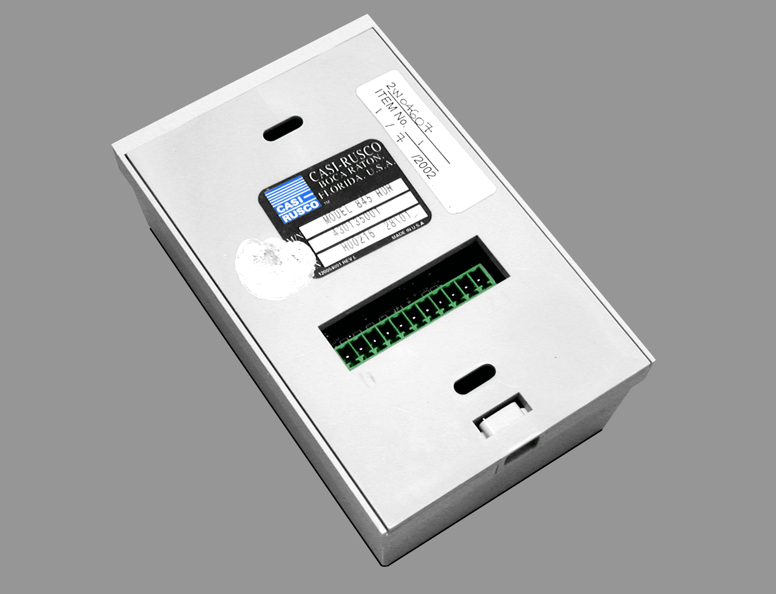
JTQ84X
Apr 18, 2002840/845 Contactless Smart Card Readers
Equipment Class
FDS - Part 15 Field Disturbance Sensor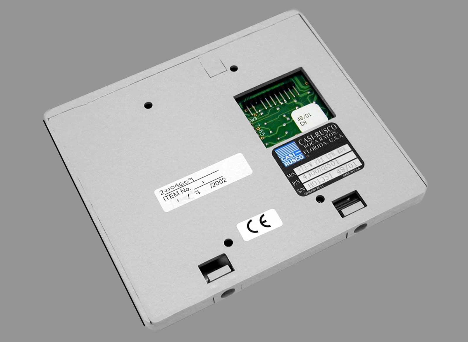
JTQ97X
Apr 17, 200297X Proximity Readers
Equipment Class
FDS - Part 15 Field Disturbance Sensor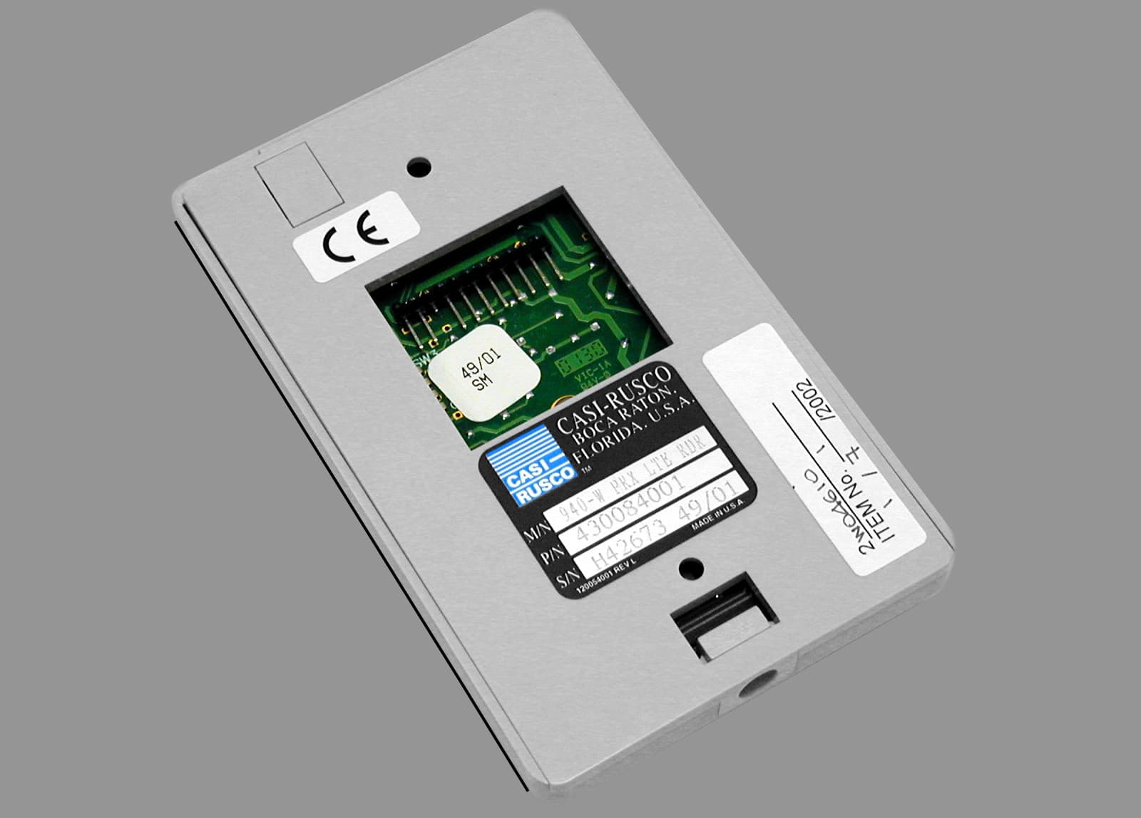
JTQ94X
Apr 14, 2002940/941 Proximity Readers
Equipment Class
FDS - Part 15 Field Disturbance SensorJTQ908
May 28, 1992FDS - Part 15 Field Disturbance Sensor
Equipment Class
FDS - Part 15 Field Disturbance Sensor