JTQ84X840/845 Contactless Smart Card Readers
Casi Rusco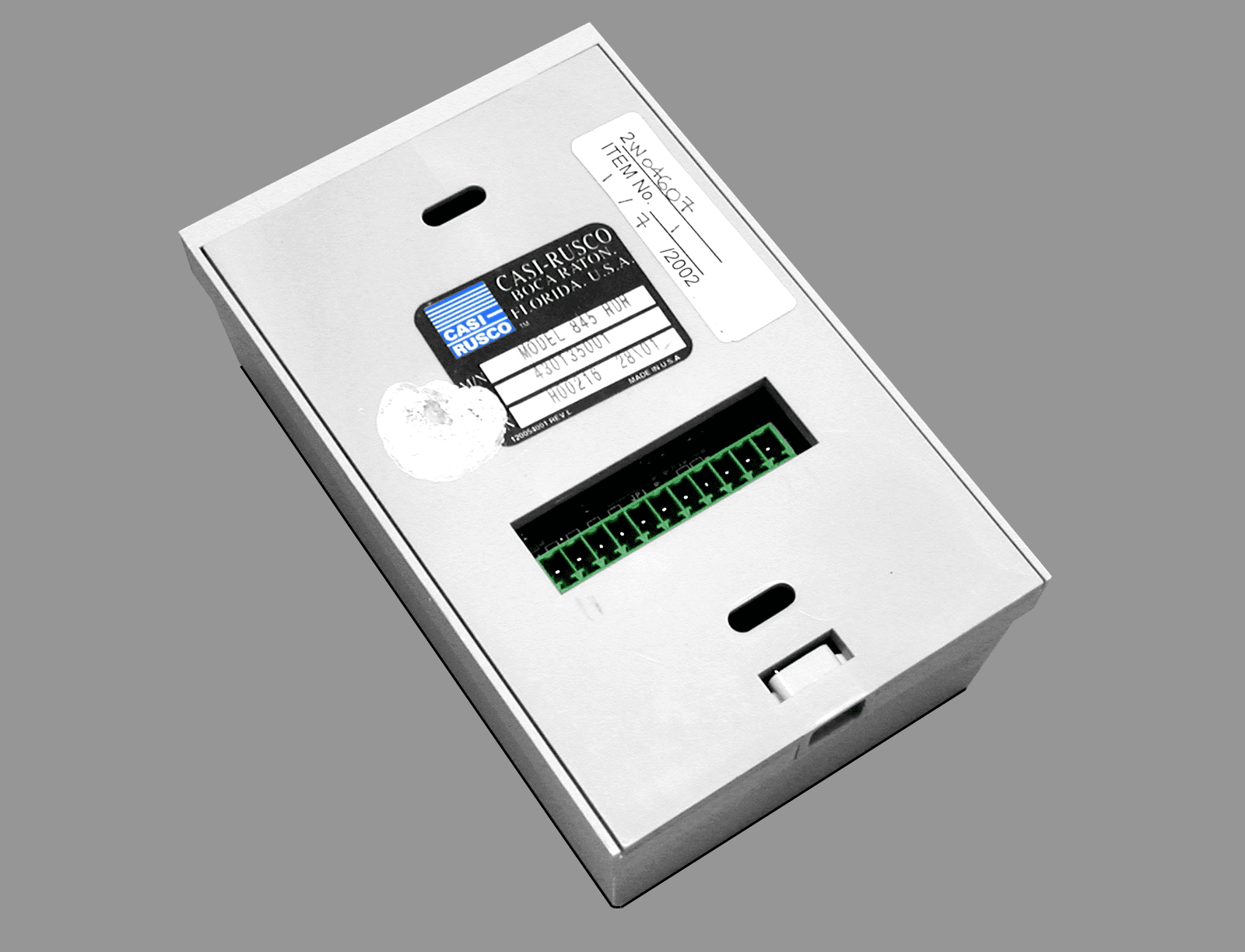
Click to zoom
Application Details
- Equipment Class
- FDS - Part 15 Field Disturbance Sensor
- Date of Grant
- Apr 18, 2002
- Application Purpose
- Original Equipment
- Date of Application
- Feb 13, 2002
- Equipment Note
- 840/845 Contactless Smart Card Readers
- Frequency Range
- 13.56000000 - 13.56000000
- Company
- Casi Rusco
- Country
- United States
Documents & Files
Document Text
Text extracted from the exhibit documents filed with the FCC. Open a document above to read the original.
Users Manual
Part Number: 460394001D January 2002 Model 840/845 Contactless Smart Card Reader Installation Guide CASIRUSCO 791 Par kof Commerce Boulevard Boca Raton, Florida 33487 (561) 998-6100 CASI-RUSCO... SecuritySolutionsforthe21 st Century This publication may contain examples of data reports used in dailybusiness operations. Examples include fictitious names of individualsand companies for illustration only; any similarity to names andaddresses of actual business enterprises and persons is entirelycoincidental.This document is distributed on an as is basis, without warranty either expressed or implied. Successful implementation depends solely uponthe customer’s ability to integrate each product into the total inventoryof “in-house” products. While each offering has been reviewed for itscompatibility and maintainability, no assurance of successfulinstallation can be given.The customer accepts full maintenance responsibility. (A full scope ofsoftware and hardware maintenance contracts are available to thecustomer.)Copyright 1999 - 2002 CASI-RUSCO All Rights ReservedPrinted in the USAProximity Perfect is a trademark of CASI-RUSCO.mifare 1 is a trademark of Philips. WARNINGThisisaClassAproduct.Inadomesticenvironmentthisproductmaycauseradiointerferenceinwhichcasetheusermayberequiredtotakeadequatemeasures. Models 840/845 Contactless Smart Card Reader i ContentsFigures ................................................................................................................ iiIntroduction ....................................................................................................... 1Product Features ............................................................................................... 2Installation Steps ............................................................................................... 3Mounting the Reader........................................................................................ 3Connecting the Reader ..................................................................................... 6 Cabling Distances ................................................................................ 6Pinouts .................................................................................................. 7 Communications Settings ................................................................................ 9 Testing for Current Settings ............................................................... 9Setting the Communications Mode (CASI-RUSCO Mode)......... 10Setting the Communications Mode (Native Mode) ..................... 11 Digital Input (Door Contact and Exit Request) Supervised F/2F Mode Only ................................................................ 13 Testing the Reader .......................................................................................... 22Troubleshooting Guide .................................................................................. 23Technical Specifications ................................................................................. 26Functional Specifications ............................................................................... 27CE Certification ................................................................................................ 30 ii Model 840/845 Contactless Smart Card Reader FiguresFigure 1: Model 84x Reader -Gang Box Mounting....................... 4 Figure 2: Model 84x Reader -Wall Mounting................................ 5 Figure 3: Model 84x Reader, J2 Connector Location.................... 8 Figure 4: Wiring Diagram, Model 84x -Supervised F/2F Mode .. 14 Figure 5: Wiring Diagram, Model 84x -Wiegand 4001 Mode ..... 16 Figure 6: Wiring Diagram, Model 84x -Unsupervised F/2F Mode .............................................................................18 Figure 7: Wiring Diagram, Model 84x -Omron/Magstripe Strobe Mode................................................................. 20 Model 840/845 Contactless Smart Card Reader 1 IntroductionThis manual is an installation guide for the CASI-RUSCO Model 840/845Contactless Smart Card Reader. Throughout this guide, the abbreviation84x will stand for reader Models 840 and 845.The 84x Reader is designed to mount on a standard U.S. single electricalgang box.The Model 845 is identical to the Model 840 except for a built-in twelvepositionkeypad.Thisfeaturemakesthisreaderidealforinstallationsrequiring keypad PIN entry in addition to a valid smart card read. 2 Model 840/845 Contactless Smart Card Reader Product FeaturesThe CASI-RUSCO Model 840/845 Contactless Smart Card Reader offersthe following features:• State-of-the-art architecture. • The ability to read all MIFARE ® 1 type Contactless Smart Cards. • The ability to read the unique serial number of a MIFARE ® 1cardand convert the hex format to twelve digits Binary Coded Decimal (BCD). • Supervised communications with the microcontroller over abidirectional F/2F data link that carries the following:• Contactless smart card ID data • Supervision messages • Exit request and door switch status • Microcontroller acknowledgments and commands • Intelligent bidirectional communication between the reader andmicrocontroller, which can be accomplished over 4-conductortelephone cable. • Weather-resistant housing for outdoor use. • Standard 12V operation. • A clear, logical user interface with three LEDs and a beeper. • Rugged, molded polycarbonate construction with integral backplate. • Built-in tamper alarm. • Two supervised digital switch inputs for interfacing exit request anddoor contact switches. •Externaltamper.• Installer programmable communications selector:• Supervised F/2F communications. • Unsupervised F/2F communications. • Omron/Magstripe Strobe communications. • Wiegand 4001 communications. • RS-232, 9600 8/N/1 communications. • UL verified for indoor use only. Model 840/845 Contactless Smart Card Reader 3 Installation StepsThe following is the general sequence of steps to follow…
Text truncated - open the document above for the full version.
Cover Letter(s)
Offices in Ottawa (Canada), USA, Norway, England, Germany, Italy, Korea, Taiwan, China and Shanghai February 14, 2002 Federal Communications Commission Equipment Authorization Branch 7435 Oakland Mills Road Columbia, Maryland 21046 USA Nemko Canada Inc. 3325 River Road RR #5 Ottawa, Ontario Canada K1V 1H2 Tel: 613-737-9680 Fax: 613-737-9691 Toll Free: 1-800-563-6336 Email: [email protected] Internet: www.nemkoca.com Dear Sir/Madam:Our File Ref. 2W04607 FCC ID: JTQ84X Applicant: Casi-Rusco Equipment: 840/845 Contactless Smart Card Readers FCC Confirmation no.: EA812138 We have successfully electronically filed all the required documentation for an application for certification in accordance with FCC Part 15, Subpart C 15.225 on the above mentioned equipment, February 14, 2002. The required fees have been paid electronically, Remittance ID: 202273, Authorization number: 092332. If you require additional information, please do not hesitate to contact me at 1-800-563-6336 (extension 232). Thank you in advance for your assistance in this matter. Sincerely, Ruby Dulmage Submissions Specialist Nemko Canada Inc. [email protected] Encl.
Operational Description
840/845 Name: Contactless Smart Card Reader Model: 430134001, 430135 001(keypad version) Serial Number: Manufacturer (If Different From Applicant): Approximate Power Requirement (Volts And Amps): +12Vdc, 140mA Approximate Size (Weight And Dimensions): 4.75”H x 3.0”W x 1.7”D Brief Description Of Equipment Construction And Theory Of Operation: Reads all mifare 1 type contactless smart cards, reads the unique serial number of the card and converts The hex format into BCD, communicates over a bi-directional line in F2/F format. 7.0 Additional Information Product Operation: The reader reads the unique manufacturer’s serial number, converts it to BCD and sends it to the micro. Switch Inputs: The reader monitors and reports the status of a normally closed supervised door contact switch and a normally open supervised exit request pushbutton. Supervised F/2F Mode Operation: The reader sends smart card data or reader status data to the microcontroller approximately once every second and waits for an acknowledgment from the microcontroller. The reader continues sending the data until an acknowledgment is received. If an acknowledgment is not received after the third attempt, the reader stops reading smart cards, the red LED starts flashing slowly (every 2 seconds), and a short triple beep sounds every 30 seconds. Once the reader receives an acknowledgment, it begins reading smart cards again, the beeper stops sounding and the red LED stops flashing. Card Read Operation: Each time the reader reads a smart card, the yellow LED blinks off briefly and the beeper sounds. On systems configured for PIN entry, the green LED flashes to indicate that keypad data is expected. PIN Code Entry: All PIN codes must be entered in this format: * x x x x # This applies to Model 845 applicable modes only. Reader Tamper Operation: The 84x Readers incorporate a tamper switch. While the reader is separated from its backplate, all normal smart card reading functions are disabled and a tamper condition is indicated by a triple beep every 30 seconds. The red LED flashes quickly (every 400 ms) and all communications with the microcontroller are suspended, taking the reader off-line. The reader is also equipped with an external tamper feature. To activate this feature, connect a single-pole, single-throw (SPST), normally- closed pushbutton switch (installer-supplied) to connector JP3 on the printed circuit board assembly and install the switch between the wall and reader backplate. When the reader and the backplate are removed from the wall, the switch will close; therefore, closing the connection, causing a tamper condition.
Test Report
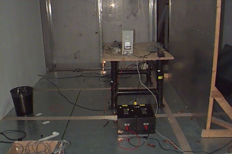
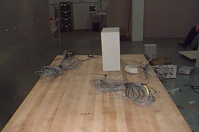
Master: PT15209 Date: December 12, 2001 Test Report:2W04607 Applicant:Casi-Rusco 791 Park of Commerce Blvd., Suite 100 Boca Raton, FL 33487 USA Equipment Under Test:840/845 Contactless Smart Card Readers (EUT) In Accordance With:FCC Part 15, Subpart C, 15.225 Tested By:Nemko Canada Inc. 3325 River Road, R.R. 5 Ottawa, Ontario K1V 1H2 Authorized By: G. Westwell, Wireless Technologist Date:January 15, 2002 Total Number of Pages:11 Authorized Copy:Soft Copy Nemko Canada Inc.FCC PART 15, SUBPART C, 15.225 PROJECT NO.: 2W04607 EQUIPMENT: 840/845 Contactless Smart Card Readers Page 2 of 11 Table Of Contents Section 1. Summary Of Test Results.....................................................................................3 Section 2. General Equipment Specification........................................................................6 Section 3. Radiated Emissions...............................................................................................7 Section 4. Frequency Stability...............................................................................................9 Section 5. Block Diagrams...................................................................................................10 Section 6. Test Equipment List...........................................................................................11 Nemko Canada Inc.FCC PART 15, SUBPART C, 15.225 PROJECT NO.: 2W04607 EQUIPMENT: 840/845 Contactless Smart Card Readers Page 3 of 11 Section 1.Summary Of Test Results General All measurements are traceable to national standards. These tests were conducted on a sample of the equipment for the purpose of demonstrating compliance with FCC Part 15, Subpart C for low power devices. All tests were conducted using measurement procedure ANSI C63.4-1992. Radiated Emissions were made on an open area test site. A description of the test facility in on file with the FCC. THIS TEST REPORT RELATES ONLY TO THE ITEM(S) TESTED. THE FOLLOWING DEVIATIONS FROM, ADDITIONS TO, OR EXCLUSIONS FROM THE TEST SPECIFICATIONS HAVE BEEN MADE. See “ Summary of Test Data”. TESTED BY: DATE: January 11, 2002 Russell Grant, Wireless Group Manager Nemko Canada Inc., a testing laboratory, is accredited by the Standards Council of Canada. The tests included in this report are within the scope of this accreditation. The results apply only to the samples tested. Nemko Canada Inc. authorizes the above named company to reproduce this report provided it is reproduced in its entirety and for use by the company’s employees only. Any use which a third party makes of this report, or any reliance on or decisions to be made based on it, are the responsibility of such third parties. Nemko Canada Inc. accepts no responsibility for damages, if any, suffered by any third party as a result of decisions made or actions based on this report. This report applies only to the items tested. Nemko Canada Inc.FCC PART 15, SUBPART C, 15.225 PROJECT NO.: 2W04607 EQUIPMENT: 840/845 Contactless Smart Card Readers Page 4 of 11 Summary Of Test Data Name Of TestPara. No.Result Powerline Conducted Emissions15.207N/A Radiated Emissions15.225Complies Frequency Stability15.225Complies Footnotes For N/A’s:12 VDC Primary Power Test Conditions: IndoorTemperature:20 °C Humidity:40 % OutdoorTemperature:21 °C Humidity:50 % Nemko Canada Inc.FCC PART 15, SUBPART C, 15.225 PROJECT NO.: 2W04607 EQUIPMENT: 840/845 Contactless Smart Card Readers Page 5 of 11 Nemko Canada Inc.FCC PART 15, SUBPART C, 15.225 PROJECT NO.: 2W04607 EQUIPMENT: 840/845 Contactless Smart Card Readers Page 6 of 11 Section 2.General Equipment Specification Manufacturer: Casi-Rusco Model No.: 840, 845 Serial No.: H00216 28/01 Date Received In Laboratory: January 7, 2002 Nemko Identification No.: Item #1 Tx: 13.56 MHz Fixed Emission Designator: NON Nemko Canada Inc.FCC PART 15, SUBPART C, 15.225 PROJECT NO.: 2W04607 EQUIPMENT: 840/845 Contactless Smart Card Readers Page 7 of 11 Section 3.Radiated Emissions Para. No.: 15.225 Test Performed By: Russell GrantDate of Test: January 9, 2002 Minimum Standard: Spurious Emissions (MHz) Field Strength (μμV/m) Field Strength (dBμμV) 0.009 - 0.4902400/F(kHz) @ 300m— 0.490 - 1.70524000/F(kHz) @ 30m— 1.705 - 3030 @ 30m— 30 - 8810040.0 88 - 21615043.5 216 - 96020046.0 Above 96050054.0 Test Results:Complies. Measurement Data:See attached table. Measured:13.56 MHz 65.5 dBμV @ 2mPeak Detector 53.0 dBμV @ 4m10 kHz RBW 12.5 dB/Octave 2 to 30, 3.9 Octave Field Strength:65.5 – 3.9 x 12.5 = 16.8 dBμV/m The spectrum was searched from 10 kHz to 1 GHz for spurious emissions. No emissions were detected within 20 dB of the limit. The equipment was configured on 3 axis in order to maximize emissions. Nemko Canada Inc.FCC PART 15, SUBPART C, 15.225 PROJECT NO.: 2W04607 EQUIPMENT: 840/845 Contactless Smart Card Readers Page 8 of 11 Radiated Emissions Photograph Front View: Nemko Canada Inc.FCC PART 15, SUBPART C, 15.225 PROJECT NO.: 2W04607 EQUIPMENT: 840/845 Contactless Smart Card Readers Page 9 of 11 Section 4.Frequency Stability Para. No.: 15.225 Test Performed By: Russell GrantDate of Test: January 9, 2002 Minimum Standard:0.01%, 100 ppm, 1356 Hz Test Results:Complies. Measurement Data:STV: 12 VDC Test ConditionFrequency (Hz) Frequency Drift (Hz) 20°C, ± STV, STV 13.561 5470 -20°C, STV 13.561 61467 -10°C, STV 13.561 61467 0°C, STV 13.561 61467 +10°C, STV 13.561 60659 +30°C, STV 13.561 59043 +40°C, STV 13.561 57629 +50°C, STV 13.561 489-58 Nemko Canada Inc.FCC PART 15, SUBPART C, 15.225 PROJECT NO.: 2W04607 EQUIPMENT: 840/845 Contactless Smart Card Readers Page 10 of 11 Section 5.Block Diagrams Radiated Prescan SPECTRUM ANALYZER AND PLOTTER OR TEST RECEIVER COMPUTER ANTENNA EUT SHIELDED ROOM Test Site For Radiated Emissions Frequency Stability EUT Spectrum Analyzer 3 METERS E.U.T. NON-CONDUCTING TURN-TABLE 0.8 METER VARIABLE SEARCH HEIGHT (1 TO 4 m) TO TEST RECEIVER/SPECTRUM ANALYZER SEARCH ANTENNA Nemko Canada Inc.FCC PART 15, SUBPART C, 15.225 PROJECT N…
Text truncated - open the document above for the full version.
Test Report
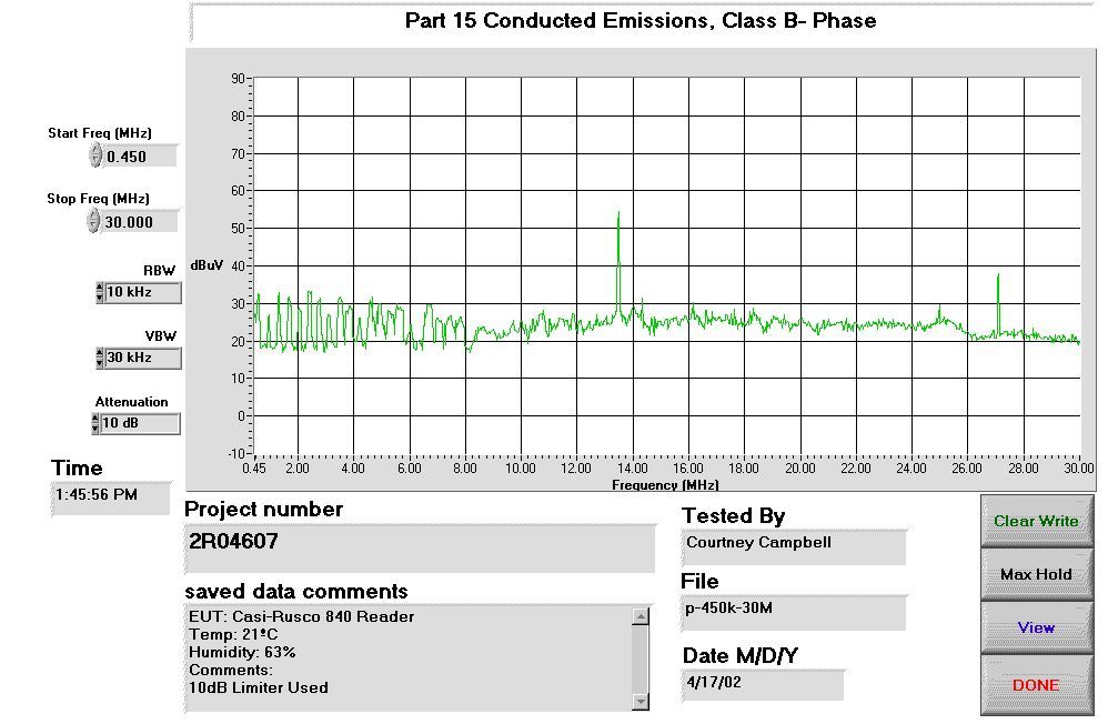
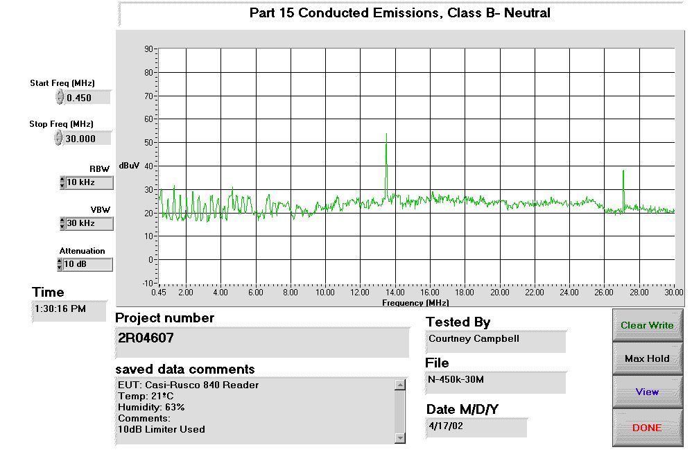
Measurement Data ConductorFrequency (MHz) CISPR (dBμV) Average (dBμV) BB/NBBB Corr. (dB) Result (dBμV) Neutral13.479934.1N/AN/AN/A34.1 Neutral27.12346.2N/AN/AN/A46.2 Phase13.479934.2N/AN/AN/A34.2 Phase27.12345.9N/AN/AN/A45.9
Contact Information
Applicant
Rafael Martinez(Sustaining Engineer)
Technical Contact
Non-Technical Contact
Nemko Canada Inc.Ruby Dulmage
[email protected]800-563-6336
Test Firm
Nemko Canada Inc.Stuart Beck
Technical Specifications
| # | Rule Parts | Frequency Range | Power Output |
|---|---|---|---|
| 1 | 15C | 13.56 MHz - 13.56 MHz | - |
Other Applications from Casi Rusco

JTQ950-960
Apr 21, 2002950/960 Proximity Readers
Equipment Class
FDS - Part 15 Field Disturbance Sensor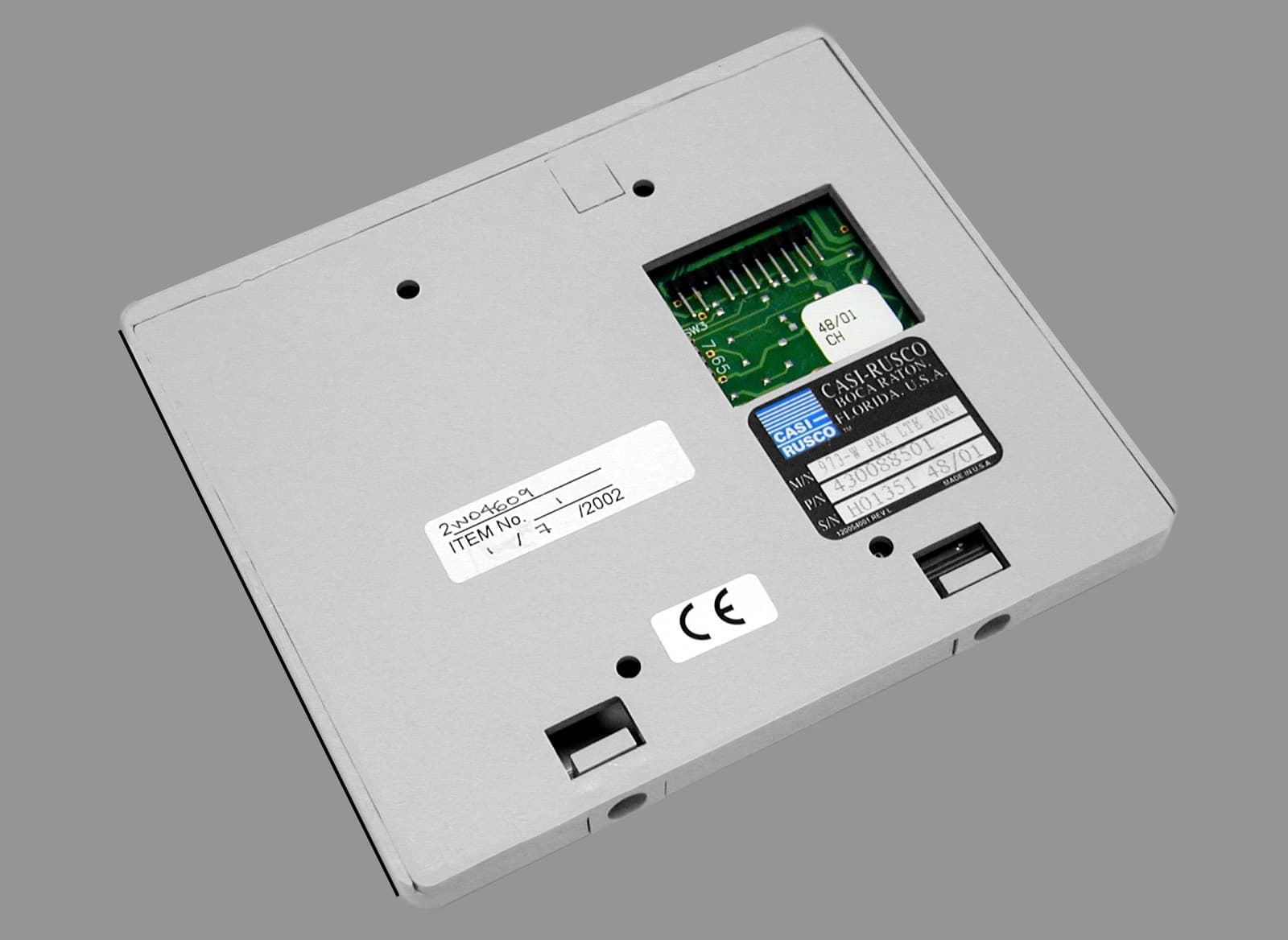
JTQ97X
Apr 17, 200297X Proximity Readers
Equipment Class
FDS - Part 15 Field Disturbance Sensor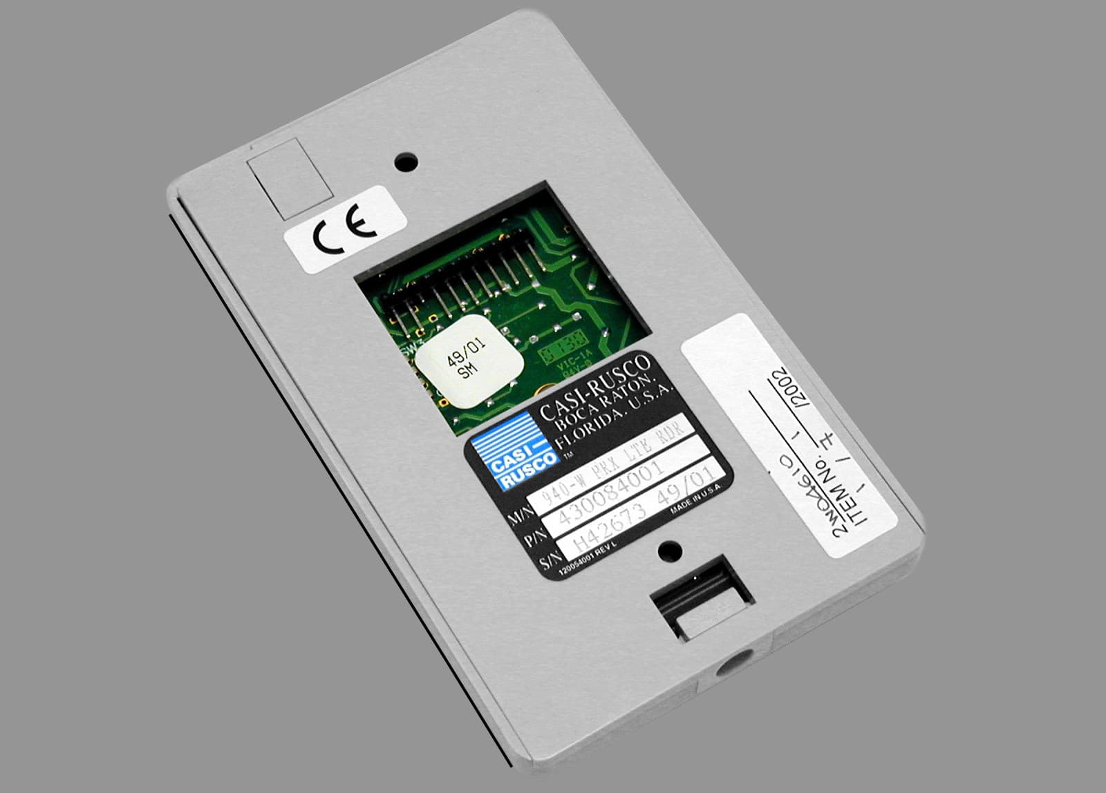
JTQ94X
Apr 14, 2002940/941 Proximity Readers
Equipment Class
FDS - Part 15 Field Disturbance Sensor
JTQ1000-1010
Sep 24, 20001000/1010 Access Control Reader
Equipment Class
FDS - Part 15 Field Disturbance SensorJTQ908
May 28, 1992FDS - Part 15 Field Disturbance Sensor
Equipment Class
FDS - Part 15 Field Disturbance Sensor