JTQ950-960950/960 Proximity Readers
Casi Rusco
Click to zoom
Application Details
- Equipment Class
- FDS - Part 15 Field Disturbance Sensor
- Date of Grant
- Apr 21, 2002
- Application Purpose
- Original Equipment
- Date of Application
- Feb 13, 2002
- Equipment Note
- 950/960 Proximity Readers
- Frequency Range
- 0.12500000 - 0.12500000
- Company
- Casi Rusco
- Country
- United States
Documents & Files
Document Text
Text extracted from the exhibit documents filed with the FCC. Open a document above to read the original.
Users Manual
Part Number: 460158001H March 2001 Model 950/960 Proximity Reader Installation Guide CASIRUSCO 791 Park of Commerce Boulevard Boca Raton, Florida 33487 (561) 998-6100 CASI-RUSCO... Security Solutions for the 21 st Century This publication may contain examples of data reports used in dailybusiness operations. Examples include fictitious names of individualsand companies for illustration only; any similarity to names andaddresses of actual business enterprises and persons is entirelycoincidental.This document is distributed on an as is basis, without warranty either expressed or implied. Successful implementation depends solely uponthe customer’s ability to integrate each product into the total inventoryof “in-house” products. While each offering has been reviewed for itscompatibility and maintainability, no assurance of successfulinstallation can be given.The customer accepts full maintenance responsibility. (A full scope ofsoftware and hardware maintenance contracts are available to thecustomer.)Copyright 1993 - 1995, 1999 - 2001 CASI-RUSCOAll Rights ReservedPrinted in the USAProximity Perfect, ProxLite, ISO ProxLite, and Entrée are trademarks ofCASI-RUSCO. Model 950/960 Proximit y Reader i ContentsIntroduction ................................................................................................ 1Product Features ........................................................................................ 1Switch Settings ........................................................................................... 3 Selecting Reader Power Level .................................................... 3Selecting Operating Mode........................................................... 7Selecting Internal Beeper Sound Level ...................................... 7 Mounting the Interface Unit..................................................................... 8Mounting the 950 Read Head .................................................................. 9Mounting the 960 Read Head ................................................................ 10Connecting the Reader ............................................................................ 12 CE/FCC Compliancy ................................................................. 12Connecting the Interface Unit to the Read Head(s)............... 14 Pinouts ....................................................................................................... 15Testing the Reader ................................................................................... 24Troubleshooting Guide ........................................................................... 25 All Installations ........................................................................... 25Unsupervised Modes Only ....................................................... 27Supervised Modes Only ............................................................ 27 Technical Specifications .......................................................................... 30Functional Specifications ........................................................................ 32 ii Model 950/960 Proximity Reader FiguresFigure 1: Interface Unit - Printed Circuit Board ............................ 4 Figure 2: Mounting the Interface Unit ............................................ 8 Figure 3: Model 950 Reader - Mullion Mount ................................ 9 Figure 4: Model 960 Reader - Glass Mount ................................ 11 Figure 5: Typical Installation Using Shielded Cable/Drain Wire .. 13 Figure 6: Interface Unit to Read Head Connection ..................... 14 Figure 7: Read Head Cable Pinouts............................................ 17 Figure 8: Wiring Diagram, Model 950/960 - Supervised F/2F Mode.................................................................... 18 Figure 9: Wiring Diagram, Model 950/960 - Unsupervised F/2F Mode.................................................................... 20 Figure 10: Wiring Diagram, Model 950/960 - Unsupervised Wiegand Mode ............................................................ 22 Figure 11: Badge to Reader Presentation..................................... 32 Model 950/960 Proximit y Reader 1 IntroductionThis manual is an installation guide for the CASI-RUSCO Models 950 and960 Proximity Perfect ™ Readers. The Model 950 Reader is intended to be mounted on the surface of a window mullion or door frame, and it isspecially tuned for installation on metal. The Model 960 Reader isintended to be mounted directly on glass and has double-sided indicatorsand a bi-directional read range.Both readers consist of a metal boxed interface unit to be mounted in asecured area and one or two compact read heads that communicate overtotal cable lengths of up to 400 to 500 feet. The interface unit contains thecircuitry that drives any combination of up to two Model 950 or 960 readheads. This performance is based on read heads manufactured afterSeptember 1, 2000. NOTE: For read heads manufactured prior to December, 2000, and mixedheads, refer to the section entitled “Pinouts” beginning on page 15. Thecable length for read heads manufactured prior to December, 2000, remainsat 15 feet.Product FeaturesThe CASI-RUSCO Models 950 and 960 Proximity Perfect Readers offer:• State-of-the-art architecture. • The ability to read all ProxLite, ISO ProxLite, and Entrée badges. • Miniature, unobtrusive read head design. • Badge read range up to 4.3 inches (110 mm) for a Model 950 and 5.5 inches (140 mm) for a Model 960. • A maximum of two 950 and 960 read heads may be connected to asingle interface unit, both acting as the same reader. • If two read heads are used, each can be mounted up to 200 feet from the interface, for a total of 400 feet of cable between the two heads. • The Model 960 read head mounted on the secured side of a windowcanreadbadgesontheunsecuredside. • DIP switches allow all Models 950 and 960 Readers to operate in one of four distinct operating mode…
Text truncated - open the document above for the full version.
Cover Letter(s)
Offices in Ottawa (Canada), USA, Norway, England, Germany, Italy, Korea, Taiwan, China and Shanghai February 14, 2002 Federal Communications Commission Equipment Authorization Branch 7435 Oakland Mills Road Columbia, Maryland 21046 USA Nemko Canada Inc. 3325 River Road RR #5 Ottawa, Ontario Canada K1V 1H2 Tel: 613-737-9680 Fax: 613-737-9691 Toll Free: 1-800-563-6336 Email: [email protected] Internet: www.nemkoca.com Dear Sir/Madam:Our File Ref. 2W04608 FCC ID: JTQ950-960 Applicant: Casi-Rusco Equipment: 950/960 Proximity Readers FCC Confirmation no.: EA212658 We have successfully electronically filed all the required documentation for an application for certification in accordance with FCC Part 15, Subpart C 15.209 on the above mentioned equipment, February 14, 2002. The required fees have been paid electronically, Remittance ID: 202282, Authorization number: 098195. If you require additional information, please do not hesitate to contact me at 1-800-563-6336 (extension 232). Thank you in advance for your assistance in this matter. Sincerely, Ruby Dulmage Submissions Specialist Nemko Canada Inc. [email protected] Encl.
Operational Description
950/960 Name: Proximity Reader Model: 430090001; 430091001 Serial Number: Manufacturer (If Different From Applicant): Approximate Power Requirement (Volts And Amps): +12Vdc, 200mA Approximate Size (Weight And Dimensions): 950: 3.0”H x 1.75”W x 0.50”D 960: 3.05”x1.8”x0.8” Brief Description Of Equipment Construction And Theory Of Operation: The reader provides an energy field that will activate a passive card. The reader detects , demodulates and validates the digital stream sent by the card. Upon validation of the of the data stream, the reader will transmit that same data via a 2kHz F/2F format to the Microcontroller where the determination is made if the user has access to the controlled area/door. 950 is intended to mount on the door frame of a window, tuned for metal; 960 mounts directly on glass and has double sided indicators Modes : 1. Both readers consist of an interface (separate metal box) mounted in a secure area and 1 or 2 compact readheads that communicate over a total cable lengths of up to 400 to 500 ft. The interface unit contains the circuitry that drives the readheads. 4. 5. Configurations : 1. Reader can be configured to read up to 4.3” (dip switch configurable) for 950, 5.5” for 960 2. Reader can be configured for different formats (unsupervised, supervised, wiegand—dip switch on interface unit) 3. 960 mounted on glass has double sided indicators and a bi-directional read range. 7.0 Additional Information 1. The reader used a single processor with a 12MHz clock frequency. There are no external address or data lines. 2. A 2MHz signal form the processor is divided down to 125kHz to drive the antenna 3. The antenna circuit is parallel tunes which shunts the harmonic energy through the capacitance rather than the inductive component (antenna). Shielded twisted pairs are used to connect the readers to the M/5 4. An active bandpass filter in the receiver section rejects signals outside the spectrum generated by the ID badges. 5. Transient protection is provided by series resistance and diode-device on the I/O lines. This product was designed to tolerate line-induced transients as well as ESD transients
Test Report
Master: PT15209 Date: December 12, 2001 Test Report:2W04608 Applicant:Casi-Rusco 791 Park of Commerce Blvd., Suite 100 Boca Raton, FL 33487 USA Equipment Under Test:950, 960 (EUT)Proximity Reader In Accordance With:FCC Part 15, Subpart C, 15.209 Tested By:Nemko Canada Inc. 3325 River Road, R.R. 5 Ottawa, Ontario K1V 1H2 Authorized By: G. Westwell, Wireless Technologist Date:January 15, 2002 Total Number of Pages:12 Authorized Copy:Soft Copy Nemko Canada Inc.FCC PART 15, SUBPART C, 15.209 PROJECT NO.: 2W04608 EQUIPMENT: 950, 960 - Proximity Reader Page 2 of 12 Table Of Contents Section 1. Summary Of Test Results.....................................................................................3 Section 2. General Equipment Specification........................................................................5 Section 3. Radiated Emissions...............................................................................................7 Section 4. Block Diagrams...................................................................................................11 Section 5. Test Equipment List...........................................................................................12 Nemko Canada Inc.FCC PART 15, SUBPART C, 15.209 PROJECT NO.: 2W04608 EQUIPMENT: 950, 960 - Proximity Reader Page 3 of 12 Section 1.Summary Of Test Results General All measurements are traceable to national standards. These tests were conducted on a sample of the equipment for the purpose of demonstrating compliance with FCC Part 15, Subpart C for low power devices. All tests were conducted using measurement procedure ANSI C63.4-1992. Radiated Emissions were made on an open area test site. A description of the test facility in on file with the FCC. THIS TEST REPORT RELATES ONLY TO THE ITEM(S) TESTED. THE FOLLOWING DEVIATIONS FROM, ADDITIONS TO, OR EXCLUSIONS FROM THE TEST SPECIFICATIONS HAVE BEEN MADE. See “ Summary of Test Data”. TESTED BY: DATE: January 15, 2002 Russell Grant, Wireless Group Manager Nemko Canada Inc., a testing laboratory, is accredited by the Standards Council of Canada. The tests included in this report are within the scope of this accreditation. The results apply only to the samples tested. Nemko Canada Inc. authorizes the above named company to reproduce this report provided it is reproduced in its entirety and for use by the company’s employees only. Any use which a third party makes of this report, or any reliance on or decisions to be made based on it, are the responsibility of such third parties. Nemko Canada Inc. accepts no responsibility for damages, if any, suffered by any third party as a result of decisions made or actions based on this report. This report applies only to the items tested. Nemko Canada Inc.FCC PART 15, SUBPART C, 15.209 PROJECT NO.: 2W04608 EQUIPMENT: 950, 960 - Proximity Reader Page 4 of 12 Summary Of Test Data Name Of TestPara. No.Result Powerline Conducted Emissions15.207N/A Radiated Emissions15.209Complies Footnotes For N/A’s:12 VDC external power supply. Test Conditions: IndoorTemperature:24 °C Humidity:53 % OutdoorTemperature:24 °C Humidity:53 % Nemko Canada Inc.FCC PART 15, SUBPART C, 15.209 PROJECT NO.: 2W04608 EQUIPMENT: 950, 960 - Proximity Reader Page 5 of 12 Section 2.General Equipment Specification Manufacturer: Casi Rusco Model No.: 950 Serial No.: None Date Received In Laboratory: July 17, 2001 Nemko Identification No.: Item #8 Tx: 125 kHz Emission Designator: NON Nemko Canada Inc.FCC PART 15, SUBPART C, 15.209 PROJECT NO.: 2W04608 EQUIPMENT: 950, 960 - Proximity Reader Page 6 of 12 Nemko Canada Inc.FCC PART 15, SUBPART C, 15.209 PROJECT NO.: 2W04608 EQUIPMENT: 950, 960 - Proximity Reader Page 7 of 12 Section 3.Radiated Emissions Para. No.: 15.209 Test Performed By: Russell GrantDate of Test: August 20, 2001 Minimum Standard: Fundamental (MHz) Field Strength (μμV/m) Field Strength (dBμμV) 0.009 - 0.4902400/F(kHz) @ 300m— 0.490 - 1.70524000/F(kHz) @ 30m— 1.705 - 3030 @ 30m— 30 - 8810040.0 88 - 21615043.5 216 - 96020046.0 Above 96050054.0 Test Results:Complies. Measurement Data:See attached table. Nemko Canada Inc.FCC PART 15, SUBPART C, 15.209 PROJECT NO.: 2W04608 EQUIPMENT: 950, 960 - Proximity Reader Page 8 of 12 Test Data - Radiated Emissions Frequency of Emission (MHz) Received Signal (dBuV/m@2m) Received Signal (dBuV/m@4m) Extrapolated Signal (dBuV/m) Limit (dBuV/m) Margin (dB) 0.12598.381.1-26.025.751.7 0.37564.846.8-65.316.181.4 0.62557.140.0-9.731.741.4 0.87554.537.5-11.928.840.7 1.12548.732.0-16.526.643.1 1.37546.030.0-16.524.841.3 1.62544.428.5-17.723.441.1 1.87539.223.7-21.429.550.9 2.12539.924.5-20.329.549.8 2.37537.022.0-21.629.551.1 2.62536.224.0-11.529.541.0 2.87536.224.6-9.129.538.7 3.12533.022.3-8.829.538.3 3.37532.924.0-1.929.531.4 3.62532.826.37.429.522.1 3.87533.826.24.129.525.4 4.12535.528.16.629.523.0 4.62525.315.5-13.029.542.5 4.87525.517.9-4.229.533.7 5.12522.910.6-25.229.554.7 Notes: Measured: Active Loop Antenna, Test Receiver 10 kHz RBW, Peak Detector Nemko Canada Inc.FCC PART 15, SUBPART C, 15.209 PROJECT NO.: 2W04608 EQUIPMENT: 950, 960 - Proximity Reader Page 9 of 12 Test Data - Radiated Emissions Test Distance (meters) : 3 Range: A Tower Receiver: ESVP RBW(kHz): 120 Detector: Q-Peak Freq. (MHz) Ant. * Pol. (V/H) RCVD Signal (dBμμV/m) Ant. Factor (dB)** Amp. Gain (dB)*** Dist. Corr. (dB) Field Strength (dBμμV/m) Limit (dBμμV/m) Margin (dB) 58.1B/C1V22.210.432.640.07.4 58.1B/C1H24.010.434.440.05.6 60.0B/C1V27.510.137.640.02.4 60.0B/C1H26.110.136.240.03.8 224.0B/C1V24.016.940.946.05.1 224.0B/C1H24.016.940.946.05.1 Notes: B/C =Biconical, B/L = Biconilog, L/P = Log-Periodic, H = Horn, D/P = Dipole *Re-measured using dipole antenna. **Includes cable loss when amplifier is not used. ***Includes cable loss. ( )Denotes failing emission level. N.D. =Not Detected Nemko Canada Inc.FCC PART 15, SUBPART C, 15.209 PROJECT NO.: 2W04608 EQUIPMENT: 950, 960 - Proximity Reader Page 10 of 12 Radiated Emissions Photographs Front View Nemko Ca…
Text truncated - open the document above for the full version.
Test Report
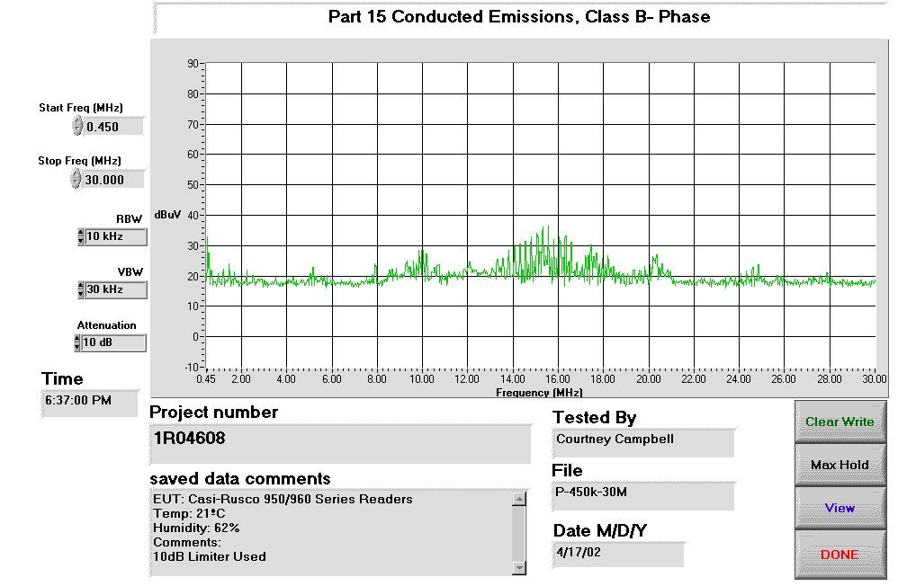
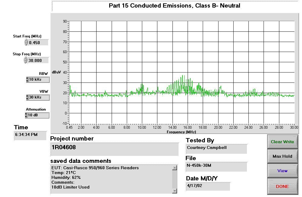
Measurement Data ConductorFrequency (MHz) CISPR (dBμV) Average (dBμV) BB/NBBB Corr. (dB) Result (dBμV) Neutral15.067622.0N/AN/AN/A22.0 Neutral15.087623.3N/AN/AN/A23.3 Neutral15.098117.0N/AN/AN/A17.0 Neutral15.124543.5N/AN/AN/A43.5 Neutral15.159316.1N/AN/AN/A16.1 Neutral14.991021.8N/AN/AN/A21.8 Neutral14.87439.6N/AN/AN/A39.6 Phase14.823220.4N/AN/AN/A20.4 Phase14.84620.5N/AN/AN/A20.5 Phase14.87440.8N/AN/AN/A40.8 Phase14.944624.0N/AN/AN/A24.0 Phase14.991520.7N/AN/AN/A20.7 Phase14.999329.9N/AN/AN/A29.9 Phase15.039421.4N/AN/AN/A21.4 Phase15.067621.1N/AN/AN/A21.1 Phase15.088122.3N/AN/AN/A22.3 Phase15.124442.5N/AN/AN/A42.5 Phase15.159214.1N/AN/AN/A14.1
Contact Information
Applicant
Rafael Martinez(Sustaining Engineer)
Technical Contact
Non-Technical Contact
Nemko Canada Inc.Ruby Dulmage
[email protected]800-563-6336
Test Firm
Nemko Canada Inc.Stuart Beck
Technical Specifications
| # | Rule Parts | Frequency Range | Power Output |
|---|---|---|---|
| 1 | 15C | 0.125 MHz - 0.125 MHz | - |
Other Applications from Casi Rusco
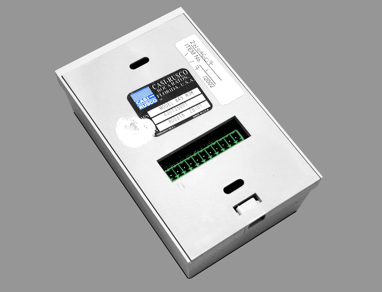
JTQ84X
Apr 18, 2002840/845 Contactless Smart Card Readers
Equipment Class
FDS - Part 15 Field Disturbance Sensor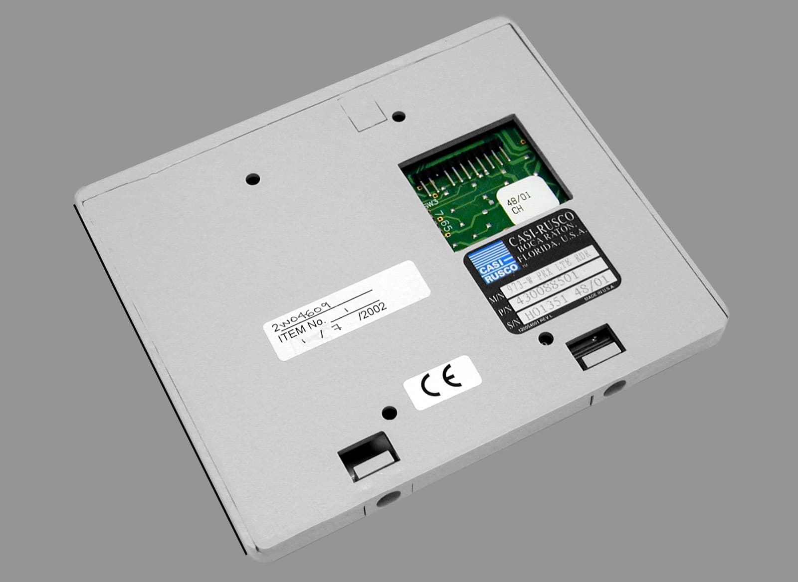
JTQ97X
Apr 17, 200297X Proximity Readers
Equipment Class
FDS - Part 15 Field Disturbance Sensor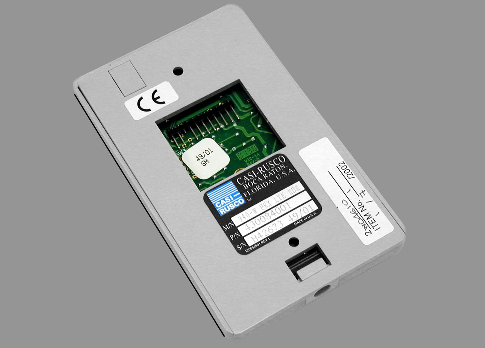
JTQ94X
Apr 14, 2002940/941 Proximity Readers
Equipment Class
FDS - Part 15 Field Disturbance Sensor
JTQ1000-1010
Sep 24, 20001000/1010 Access Control Reader
Equipment Class
FDS - Part 15 Field Disturbance SensorJTQ908
May 28, 1992FDS - Part 15 Field Disturbance Sensor
Equipment Class
FDS - Part 15 Field Disturbance Sensor