JUP-59646900MHz/2400MHz Combination Radio-Modem
Trimble, Inc.
Click to zoom
Application Details
- Equipment Class
- DSS - Part 15 Spread Spectrum Transmitter
- Date of Grant
- Jun 10, 2007
- Application Purpose
- Original Equipment
- Date of Application
- Jun 10, 2007
- Equipment Note
- 900MHz/2400MHz Combination Radio-Modem
- Frequency Range
- 2401.53000000 - 2469.75000000
- Company
- Trimble, Inc.
- Country
- United States
Documents & Files
Document Text
Text extracted from the exhibit documents filed with the FCC. Open a document above to read the original.
Users Manual
Aqua User Manual Draft June 11, 2007 Aqua User Manual..................................................................... 1 1 Introduction.................................................................................................................... 3 Welcome .........................................................................................................................3 Related Information ........................................................................................................ 3 Technical Assistance....................................................................................................... 3 Your Comments .............................................................................................................. 3 2 Getting Started.............................................................................................................. 3 Introduction..................................................................................................................... 3 Hardware Specification................................................................................................... 4 AQUA Description ......................................................................................................... 4 Features ........................................................................................................................... 5 Frequency Band .............................................................................................................. 5 3 Configuring the AQUA.................................................................................................. 6 Introduction..................................................................................................................... 6 Default Settings..............................................................Error! Bookmark not defined. WinFlash Configuration Software .................................................................................. 7 Connecting to the AQUA................................................................................................ 7 Configuring the AQUA................................................................................................... 7 Network..........................................................................Error! Bookmark not defined. Mode ..............................................................................Error! Bookmark not defined. Serial Port Baud Rate and Parity ...................................Error! Bookmark not defined. Defaults ..........................................................................Error! Bookmark not defined. Diagnostics and Firmware Upgrade................................................................................ 9 Installing the AQUA.......................................................................................................... 9 Introduction..................................................................................................................... 9 Physical Description ....................................................................................................... 9 Connectors and Indicators............................................................................................... 9 Mounting the AQUA on a Machine.............................................................................. 10 Machine Mount Kit (PN 35087-00).............................................................................. 10 Machine Mounting........................................................................................................ 10 Cabling Configurations ................................................................................................. 11 Power and I/O Cable for Machine Installations............................................................ 11 Machine Service Cable ................................................................................................. 11 Antenna Description ..................................................................................................... 11 Antenna Considerations ................................................................................................ 12 A Technical Specifications............................................................................................ 12 Technical Information................................................................................................... 12 Pinout Information ........................................................................................................ 13 Glossary ............................................................................................................................ 14 Index................................................................................................................................. 14 1 Introduction Welcome This manual describes how to set up and use an Aqua radio modem. This publication assumes that you are know how to use the Microsoft® Windows® operating system. Related Information Sources of related information include the following: Readme.txt file – a Readme.txt file contains information added after the documentation was completed. To read this file, double-click it or use a text editor to open it. The installation program also copies it into the program directory. Release notes – the release notes describe new features of the product, information not included in the manuals, and any changes to the manuals. Update notes – there is a warranty activation sheet with this product. Send it in to automatically receive update notes containing important information about software and hardware changes. Contact your local dealer for more information about the support agreement contracts for software and firmware, and an extended warranty program for hardware. Technical Assistance If you have a problem and cannot find the information you need in t…
Text truncated - open the document above for the full version.
External Photos
Trimble Navigation Ltd. FCC ID: JUP-59646 Report #: R0704044-247 Page 22 of 28 FCC Part 15.247 Test Report 8 EXHIBIT C - EUT PHOTOGRAPHS 8.1 EUT External Front View 8.2 EUT with Reverse Polarity Antenna Ports Top View Trimble Navigation Ltd. FCC ID: JUP-59646 Report #: R0704044-247 Page 23 of 28 FCC Part 15.247 Test Report 8.3 EUT with Power & Data Port Bottom View 8.4 EUT Back View
ID Label/Location Info
Trimble Navigation Ltd. FCC ID: JUP-59646 Report #: R0704044-247 Page 20 of 28 FCC Part 15.247 Test Report 6 EXHIBIT A – FCC PRODUCT LABELING AND WARNING STATEMENT 6.1 FCC ID Label The FCC labels should contain FCC statement in FCC 15.19 paragraph (3). A sample of the statement is presented hereinafter as reference. Also, as per FCC §15.19 a(4) Where a device is constructed in two or more sections connected by wires and marketed together, the statement specified above is required to be affixed only to the main control unit. If the EUT is integrated within another device then a label affixed to the host shall also state, “Contains FCC ID: XXXXXXXXX” 6.2 Proposed Label Location on EUT Back View of EUT / Proposed FCC ID Location As per FCC §15.19 (b)(4), the label shall not be a stick-on, paper label. The label on these products shall be permanently affixed to the product and shall be readily visible to the purchaser at the time of purchase, as described in Section 2.925(d) of this chapter. "Permanently affixed" means that the label is etched, engraved, stamped, silk-screened, indelibly printed, or otherwise permanently marked on a permanently attached part of the equipment or on a nameplate of metal, plastic, or other material fastened to the equipment by welding, riveting, or a permanent adhesive. The label must be designed to last the expected lifetime of the equipment in the environment in which the equipment may be operated and must not be readily detachable. FCC ID: JUP-59646 This device complies with Part 15 of the FCC Rules. Operation is subject to the following two conditions: (1) this device may not cause harmful interference, and (2) this device must accept any interference received, including interference that ma y cause undesired operation. Manufacturer: Trimble Navigation
Internal Photos
Trimble Navigation Ltd. FCC ID: JUP-59646 Report #: R0704044-247 Page 24 of 28 FCC Part 15.247 Test Report 8.5 EUT Chassis Cover off View 1 8.6 Control Board – Side 1 View Trimble Navigation Ltd. FCC ID: JUP-59646 Report #: R0704044-247 Page 25 of 28 FCC Part 15.247 Test Report 8.7 Control Board – Side 2 View 8.8 RF Board – Side 1 View (with RF shielding installed) Trimble Navigation Ltd. FCC ID: JUP-59646 Report #: R0704044-247 Page 26 of 28 FCC Part 15.247 Test Report 8.9 RF Board – Side 1 View (RF shielding removed) 8.10 RF Board – Side 2 View Trimble Navigation Ltd. FCC ID: JUP-59646 Report #: R0704044-247 Page 27 of 28 FCC Part 15.247 Test Report 8.11 Rx Front End, Transmitter and PLL Synthesizer – Side 1 View of Radio Board 8.12 2nd LO, 2nd IF and Connection Interface – Side 2 View of Radio Board Trimble Navigation Ltd. FCC ID: JUP-59646 Report #: R0704044-247 Page 28 of 28 FCC Part 15.247 Test Report 8.13 Antenna View 1 (Model: Mobile Antenna) 8.14 Antenna View 2 (Model: Mobile Antenna) END OF REPORT
RF Exposure Info
Trimble Navigation Ltd. FCCID: JUP-59645 Report #:R0703211-247 Page 42 of 44 FCC Part 15.247 Report 13 § 15.247 (i) and § 2.1091 - RF EXPOSURE 13.1 Applicable Standard According to §15.247(i) and §1.1307(b)(1), systems operating under the provisions of this section shall be operated in a manner that ensures that the public is not exposed to radio frequency energy level in excess of the Commission’s guidelines. According to §1.1310 and §2.1091 RF exposure is calculated. Limits for General Population/Uncontrolled Exposure Limits for General Population/Uncontrolled Exposure Frequency Range (MHz) Electric Field Strength (V/m) Magnetic Field Strength (A/m) Power Density (mW/cm 2 ) Averaging Time (minutes) 0.3-1.34 614 1.63 *(100) 30 1.34-30 824/f 2.19/f *(180/f 2 ) 30 30-300 27.5 0.073 0.2 30 300-1500 / / f/1500 30 1500-100,000 / / 1.0 30 f = frequency in MHz * = Plane-wave equivalent power density 13.2 MPE Prediction Predication of MPE limit at a given distance Equation from page 18 of OET Bulletin 65, Edition 97-01 S = PG/4πR² Where: S = power density P = power input to antenna G = power gain of the antenna in the direction of interest relative to an isotropic radiator R = distance to the center of radiation of the antenna Antenna Model: Antenna Mobile Test Data Maximum peak output power at antenna input terminal: 29.93(dBm ) Maximum peak output power at antenna input terminal: 984.01 (mw) Prediction distance: 20 (cm) Predication frequenc0y: 902.625(MHz) Antenna Gain (typical): 2 (dBi) Antenna gain: 1.58 (numeric) Power density at predication frequency at 20 cm: 0.3093(mW/cm 2 ) MPE limit for uncontrolled exposure at prediction frequency: 0.6(mW/cm 2 ) Trimble Navigation Ltd. FCCID: JUP-59645 Report #:R0703211-247 Page 43 of 44 FCC Part 15.247 Report Antenna Model: SPDA17918Test Data Maximum peak output power at antenna input terminal: 29.93(dBm ) Maximum peak output power at antenna input terminal: 984.01 (mw) Prediction distance: 20 (cm) Predication frequency: 902.625(MHz) Antenna Gain (typical): 2.14 (dBi) Antenna gain: 1.64 (numeric) Power density at predication frequency at 20 cm: 0.3210 (mW/cm 2 ) MPE limit for uncontrolled exposure at prediction frequency: 0.6(mW/cm 2 ) 13.3 Test Result The power density level at 20 cm is 0.3093 mW/cm² and 0.3210 mW/cm², which is below the uncontrolled exposure limit of 0.6 mW/cm² at 902.625 MHz. The EUT is used at least 20cm away from user’s body. It is determined as mobile equipment.
Test Report
Note: This test report is for the customer shown above and their specific product only. It may not be duplicated or used in part without prior written consent from Bay Area Compliance Laboratories Corp. This report must not be used by the customer to claim product certification, approval, or endorsement by NVLAP, NIST, or any agency of the Federal Government . FCC PART 15.247 MEASUREMENT AND TEST REPORT For Trimble Navigation Ltd. 935 Stewart Drive Sunnyvale, CA 94085, USA FCC ID: JUP-59646 Model: SNR910 + 2.4 GHz Report Type: Original Submission: Supplemental Report Product Type: Modular GPS Receiver with 900 & 2400 MHz FHSS Transceivers Test Engineer: Dan Coronia Report Number: R0704044-247 Report Date: 2007-05-08 Reviewed By: Daniel Deng: RF Engineering Lead Prepared By: Bay Area Compliance Laboratories Corp. (BACL) 1274 Anvilwood Ave. Sunnyvale, CA 94089 Tel: (408) 732-9162 Fax: (408) 732 9164 Trimble Navigation Ltd. FCC ID: JUP-59646 Report #: R0704044-247 Page 2 of 28 FCC Part 15.247 Test Report TABLE OF CONTENTS 1 GENERAL INFORMATION ............................................................................................................................. 4 1.1 PRODUCT DESCRIPTION FOR EQUIPMENT UNDER TEST (EUT) ....................................................................... 4 1.2 ANTENNAE DESCRIPTION...............................................................................................................................4 1.3 MECHANICAL DESCRIPTION OF EUT.............................................................................................................. 4 1.4 EUT PHOTOGRAPH......................................................................................................................................... 5 1.5 OBJECTIVE..................................................................................................................................................... 5 1.6 RELATED SUBMITTAL(S)/GRANT(S) ............................................................................................................... 6 1.7 TEST METHODOLOGY..................................................................................................................................... 6 1.8 MEASUREMENT UNCERTAINTY...................................................................................................................... 6 1.9 TEST FACILITY............................................................................................................................................... 6 2 SYSTEM TEST CONFIGURATION................................................................................................................. 7 2.1 JUSTIFICATION............................................................................................................................................... 7 2.2 EUT EXERCISE SOFTWARE............................................................................................................................ 7 2.3 SPECIAL ACCESSORIES................................................................................................................................... 7 2.4 EQUIPMENT MODIFICATIONS......................................................................................................................... 7 2.5 LOCAL SUPPORT EQUIPMENT......................................................................................................................... 7 2.6 POWER SUPPLY LINES.................................................................................................................................... 7 2.7 INTERNAL CONFIGURATION........................................................................................................................... 7 2.8 INTERFACE PORTS AND CABLING................................................................................................................... 8 2.9 TEST SETUP BLOCK DIAGRAMS..................................................................................................................... 8 3 SUMMARY OF TEST RESULTS FOR FCC PART 15 .................................................................................. 9 4 §15.203 - ANTENNA REQUIREMENT .......................................................................................................... 10 4.1 APPLICABLE STANDARD...............................................................................................................................10 4.2 RESULT........................................................................................................................................................ 10 5 §15.205, §15.209 & §15.247 - RADIATED EMISSIONS ................................................................................11 5.1 APPLICABLE STANDARD...............................................................................................................................11 5.2 TEST SETUP.................................................................................................................................................. 12 5.3 TEST EQUIPMENT LIST AND DETAILS........................................................................................................... 12 5.4 ENVIRONMENTAL CONDITIONS.................................................................................................................... 12 5.5 TEST PROCEDURE......................................................................................................................................... 13 5.6 SPURIOUS RADIATED EMISSIONS TEST DATA.............................................................................................. 14 6 EXHIBIT A – FCC PRODUCT LABELING AND WARNING STATEMENT.......................................... 20 6.1 FCC ID LABEL............................................................................................................................................. 20 6.2 PROPOSED LABEL LOCATION ON E…
Text truncated - open the document above for the full version.
Test Setup Photos
Trimble Navigation Ltd. FCC ID: JUP-59646 Report #: R0704044-247 Page 21 of 28 FCC Part 15.247 Test Report 7 EXHIBIT B – TEST SETUP PHOTOGRAPHS 7.1 Transmitter Radiated Emissions – Front View (Antenna Model: Mobile Antenna) 7.2 Transmitter Radiated Emissions – Rear View (Antenna Model: Mobile Antenna)
Contact Information
Applicant
Tony Phan(Engineering Management, GNSS Core R&D)
Test Firm
Bay Area Compliance LaboratoryJohn Chan
Technical Specifications
| # | Rule Parts | Frequency Range | Power Output |
|---|---|---|---|
| 2 | 15C | 2.40 GHz - 2.47 GHz | 64.00 mW |
Other Applications from Trimble, Inc.
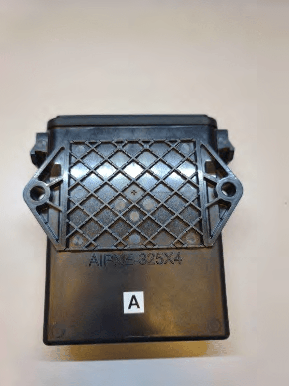
JUP-SMSE013
Apr 16, 2024RFID Read/Writer for Chemical and Fertilizer application system
Equipment Class
DSS - Part 15 Spread Spectrum Transmitter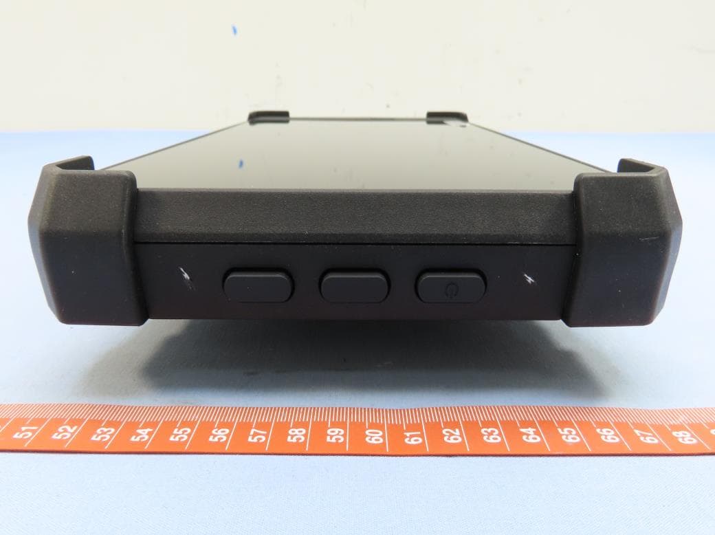
JUP-TD540
Jul 17, 202210 inch Touch Display
Equipment Class
DXX - Part 15 Low Power Communication Device Transmitter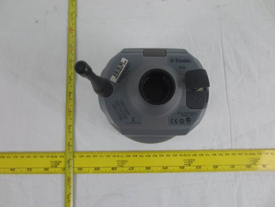
JUP-9091191
Jan 15, 2015GNSS Receiver+900 MHz+Wi-Fi+Bluetooth
Equipment Class
DSS - Part 15 Spread Spectrum Transmitter
JUP-95807WFBT
Sep 14, 2014WLAN+ Bluetooth Combo Module
Equipment Class
DSS - Part 15 Spread Spectrum Transmitter
JUP88161
Oct 20, 2013GeoExplorer(R) 7 Series handheld, Geo 7X
Equipment Class
DTS - Digital Transmission System