JUP-9091191GNSS Receiver+900 MHz+Wi-Fi+Bluetooth
Trimble, Inc.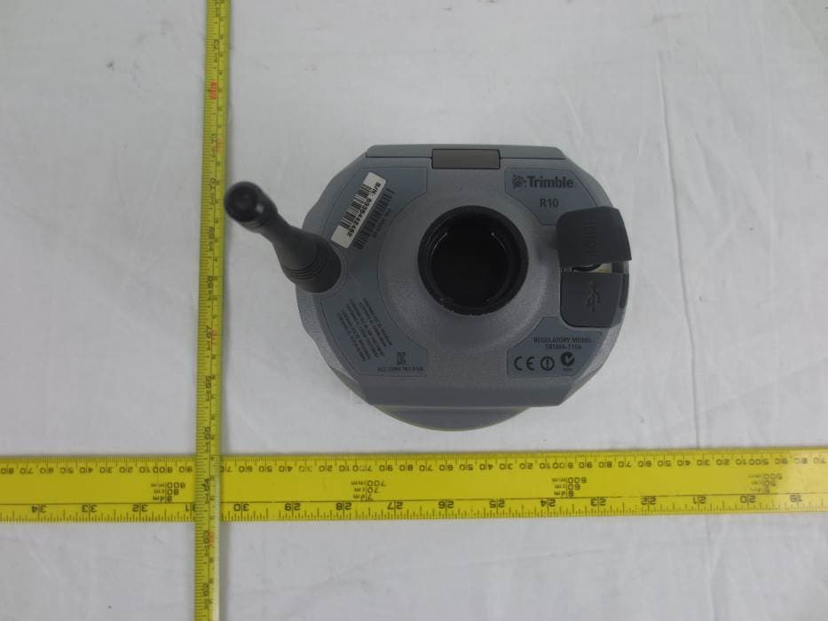
Click to zoom
Application Details
- Equipment Class
- DSS - Part 15 Spread Spectrum Transmitter
- Date of Grant
- Jan 15, 2015
- Application Purpose
- Original Equipment
- Date of Application
- Jan 15, 2015
- Equipment Note
- GNSS Receiver+900 MHz+Wi-Fi+Bluetooth
- Frequency Range
- 902.60000000 - 927.60000000
- Company
- Trimble, Inc.
- Country
- United States
Documents & Files
Document Text
Text extracted from the exhibit documents filed with the FCC. Open a document above to read the original.
Users Manual
Version1.00 RevisionB October2014 USER GUIDE Trimble R10 GNSS receiver 1 Corporate Office Trimble Navigation Limited 935 Stewart Drive Sunnyvale, CA 94085 USA www.trimble.com Geospatial Division Trimble Navigation Limited Geospatial Division 10368 Westmoor Drive Westminster, CO 80021 USA www.trimble.com Email: [email protected] Legal Notices © 2006–2014, Trimble Navigation Limited. All rights reserved. Trimble, the Globe & Triangle logo, and OmniSTAR are trademarks of Trimble Navigation Limited, registered in the United States and in other countries. CenterPoint, CMR+, Connected Community, EVEREST, HD- GNSS, HYDROpro, Maxwell, RTX, SurePoint, Trimble Access, TRIMMARK, VRS, and xFill are trademarks of Trimble Navigation Limited. Microsoft, Internet Explorer, Silverlight, Windows, and Windows Vista are either registered trademarks or trademarks of Microsoft Corporation in the United States and/or other countries. The Bluetooth word mark and logos are owned by the Bluetooth SIG, Inc. and any use of such marks by Trimble Navigation Limited is under license. All other trademarks are the property of their respective owners. Support for Galileo is developed under a license of the European Union and the European Space Agency. NTP Software Copyright © David L. Mills 1992-2009. Permission to use, copy, modify, and distribute this software and its documentation for any purpose with or without fee is hereby granted, provided that the above copyright notice appears in all copies and that both the copyright notice and this permission notice appear in supporting documentation, and that the name University of Delaware not be used in advertising or publicity pertaining to distribution of the software without specific, written prior permission. The University of Delaware makes no representations about the suitability this software for any purpose. It is provided "as is" without express or implied warranty. Release Notice This is the October 2014 release (Revision B) of the Trimble R10 GNSS receiver documentation. Product Limited Warranty Information For applicable product Limited Warranty information, please refer to the Limited Warranty Card included with this Trimble product, or consult your local Trimble authorized dealer. COCOM limits The U.S. Department of Commerce requires that all exportable GPS products contain performance limitations so that they cannot be used in a manner that could threaten the security of the United States. The following limitations are implemented on this product: – Immediate access to satellite measurements and navigation results is disabled when the receiver velocity is computed to be greater than 1,000 knots, or its altitude is computed to be above 18,000 meters. The receiver GPS subsystem resets until the COCOM situation clears. As a result, all logging and stream configurations stop until the GPS subsystem is cleared. Notices Class B Statement – Notice to Users. This equipment has been tested and found to comply with the limits for a Class B digital device, pursuant to Part 15 of the FCC rules and Part 90. These limits are designed to provide reasonable protection against harmful interference in a residential installation. This equipment generates, uses, and can radiate radio frequency energy and, if not installed and used in accordance with the instructions, may cause harmful interference to radio communication. However, there is no guarantee that interference will not occur in a particular installation. If this equipment does cause harmful interference to radio or television reception, which can be determined by turning the equipment off and on, the user is encouraged to try to correct the interference by one or more of the following measures: – Increase the separation between the equipment and the receiver. – Connect the equipment into an outlet on a circuit different from that to which the receiver is connected. – Consult the dealer or an experienced radio/TV technician for help. Changes and modifications not expressly approved by the manufacturer or registrant of this equipment can void your authority to operate this equipment under Federal Communications Commission rules. Canada This Class B digital apparatus complies with Canadian ICES-003. Cet appareil numérique de la classe B est conforme à la norme NMB-003 du Canada. This apparatus complies with Canadian RSS-GEN, RSS-310, RSS-210, and RSS-119. Cet appareil est conforme à la norme CNR-GEN, CNR-310, CNR-210, et CNR-119 du Canada. Europe The product covered by this guide are intended to be used in all EU member countries, Norway, and Switzerland. Products been tested and found to comply with the requirements for a Class B device pursuant to European Council Directive 89/336/EEC on EMC, thereby satisfying the requirements for CE Marking and sale within the European Economic Area (EEA). Contains a Bluetooth radio module. These requirements are designed to provide reasonable protection against harmful interference when the equipment is operated in a residential or commercial environment. The 450 MHZ (PMR) bands are non-harmonized throughout Europe. CE Declaration of Conformity Hereby, Trimble Navigation, declares that the GPS receivers are in compliance with the essential requirements and other relevant provisions of Directive 1999/5/EC. Australia and New Zealand This product conforms with the regulatory requirements of the Australian Communications and Media Authority (ACMA) EMC framework, thus satisfying the requirements for C-Tick Marking and sale within Australia and New Zealand. Taiwan – Battery Recycling Requirements The product contains a removable Lithium-ion battery. Taiwanese regulations require that waste batteries are recycled. 廢電池請回收 Restriction of Use of Certain Hazardous Substances in Electrical and Electronic Equipment (RoHS) Trimble products in this guide comply in all material respects with DIRECTIVE 2002/95/EC OF THE EUROPEAN PARLIAMENT AND OF THE COUNCIL of 27 January 2003 on the restric…
Text truncated - open the document above for the full version.
External Photos
Trimble Navigation Ltd.. FCC ID: JUP-9091191; IC: 1756A-9091191 Report Number: R14073110-247 AC900 Page 45 of 52 FCC Part 15C/IC RSS-210 Test Report 16 Exhibit C – EUT Photographs 16.1 EUT – Top View 16.2 EUT – Bottom View Trimble Navigation Ltd.. FCC ID: JUP-9091191; IC: 1756A-9091191 Report Number: R14073110-247 AC900 Page 46 of 52 FCC Part 15C/IC RSS-210 Test Report 16.3 EUT – Side View 1 16.4 EUT – Side View 2
ID Label/Location Info
FCC/IC ID Label
Internal Photos
Trimble Navigation Ltd.. FCC ID: JUP-9091191; IC: 1756A-9091191 Report Number: R14073110-247 AC900 Page 47 of 52 FCC Part 15C/IC RSS-210 Test Report 16.5 EUT – Top View 2 (Open Case) 16.6 EUT – Top View 2 (Open Case) Trimble Navigation Ltd.. FCC ID: JUP-9091191; IC: 1756A-9091191 Report Number: R14073110-247 AC900 Page 48 of 52 FCC Part 15C/IC RSS-210 Test Report 16.7 EUT – Main Board Top View 16.8 EUT – 900 MHz Module Top View without Shielding Trimble Navigation Ltd.. FCC ID: JUP-9091191; IC: 1756A-9091191 Report Number: R14073110-247 AC900 Page 49 of 52 FCC Part 15C/IC RSS-210 Test Report 16.9 EUT – 900 MHz Module Bottom View without Shielding 16.10 EUT – 900 MHz Module Bottom View without Shielding Trimble Navigation Ltd.. FCC ID: JUP-9091191; IC: 1756A-9091191 Report Number: R14073110-247 AC900 Page 50 of 52 FCC Part 15C/IC RSS-210 Test Report 16.11 EUT – WFBT Module Top View 16.12 EUT – WFBT Module Bottom View Trimble Navigation Ltd.. FCC ID: JUP-9091191; IC: 1756A-9091191 Report Number: R14073110-247 AC900 Page 51 of 52 FCC Part 15C/IC RSS-210 Test Report 16.13 EUT – GSM/UMTS Module Top View-with shield 16.14 EUT – GSM/UMTS Module Top View-without shield Trimble Navigation Ltd.. FCC ID: JUP-9091191; IC: 1756A-9091191 Report Number: R14073110-247 AC900 Page 52 of 52 FCC Part 15C/IC RSS-210 Test Report 16.15 EUT – GSM/UMTS Module Bottom View 16.16 EUT – AC/DC Adapter --- END OF REPORT ---
RF Exposure Info
Trimble Navigation Ltd.. FCC ID: JUP-9091191; IC: 1756A-9091191 Report Number: R14073110-247 AC900 Page 9 of 52 FCC Part 15C/IC RSS-210 Test Report 4 FCC §15.247 (i), §2.1091 & IC RSS-102 – RF Exposure 4.1 Applicable Standard According to FCC §15.247(i) and §1.1307(b)(1), systems operating under the provisions of this section shall be operated in a manner that ensures that the public is not exposed to radio frequency energy level in excess of the Commission’s guidelines. Limits for General Population/Uncontrolled Exposure Frequency Range (MHz) Electric Field Strength (V/m) Magnetic Field Strength (A/m) Power Density (mW/cm 2 ) Averaging Time (minutes) Limits for General Population/Uncontrolled Exposure 0.3-1.34 614 1.63 * (100) 30 1.34-30 824/f 2.19/f * (180/f 2 ) 30 30-300 27.5 0.073 0.2 30 300-1500 / / f/1500 30 1500-100,000 / / 1.0 30 f = frequency in MHz * = Plane-wave equivalent power density Before equipment certification is granted, the procedure of IC RSS-102 must be followed concerning the exposure of humans to RF fields. According to IC RSS-102 Issue 4 section 4.2, RF limits used for general public will be applied to the EUT. Frequency Range (MHz) Electric Field (V/m rms) Magnetic Field (A/m rms) Power Density (W/m 2 ) Time Averaging (min) 0.003 - 1 280 2.19 - 6 1 - 10 280 / f 2.19 / f - 6 10 - 30 28 2.19 / f - 6 30 – 300 28 0.073 2* 6 300 – 1 500 1.585 f 0.5 0.0042 f 0.5 f / 150 6 1 500 – 15 000 61.4 0.163 10 6 15 000 – 150 000 61.4 0.163 10 616000 / f 1.2 150 000- 300 000 0.158 f 0.5 4.21 x 10 -4 f 0.5 6.67 x 10 -5 f 616000 / f 1.2 Note: ƒ is frequency in MHz * = Power density limit is applicable at frequencies greater than 100 MHz Trimble Navigation Ltd.. FCC ID: JUP-9091191; IC: 1756A-9091191 Report Number: R14073110-247 AC900 Page 10 of 52 FCC Part 15C/IC RSS-210 Test Report 4.2 MPE Prediction Predication of MPE limit at a given distance, Equation from OET Bulletin 65, Edition 97-01 S = PG/4R² Where: S = power density P = power input to antenna G = power gain of the antenna in the direction of interest relative to an isotropic radiator R = distance to the center of radiation of the antenna 4.3 MPE Results Note: The EUT contains the following modules which can transmit simultaneously. 902-928 MHz: Maximum peak output power at antenna input terminal (dBm): 29.96 Maximum peak output power at antenna input terminal (mW): 990.83 Prediction distance (cm): 50 Prediction frequency (MHz): 927.6 Maximum Antenna Gain, typical (dBi): 3 Maximum Antenna Gain (numeric): 1.99 Power density of prediction frequency at 50.0 cm (mW/cm 2 ): 0.0629 MPE limit for uncontrolled exposure at prediction frequency (mW/cm 2 ): 0.6184 MPE Percentage: 0.0629/0.6184*100% = 10.17% 2.4 GHz Wi-Fi: Maximum peak output power at antenna input terminal (dBm): 14.85 Maximum peak output power at antenna input terminal (mW): 30.549 Prediction distance (cm): 50 Prediction frequency (MHz): 2412 Maximum Antenna Gain, typical (dBi): 4 Maximum Antenna Gain (numeric): 2.511 Power density of prediction frequency at 50.0 cm (mW/cm 2 ): 0.02443 MPE limit for uncontrolled exposure at prediction frequency (mW/cm 2 ): 1.0 MPE Percentage: 0.002443/1.0*100% = 0.24% Trimble Navigation Ltd.. FCC ID: JUP-9091191; IC: 1756A-9091191 Report Number: R14073110-247 AC900 Page 11 of 52 FCC Part 15C/IC RSS-210 Test Report 2.4 GHz BT: Maximum peak output power at antenna input terminal (dBm): 2.16 Maximum peak output power at antenna input terminal (mW): 1.644 Prediction distance (cm): 50 Prediction frequency (MHz): 2402 Maximum Antenna Gain, typical (dBi): 4 Maximum Antenna Gain (numeric): 2.511 Power density of prediction frequency at 50.0 cm (mW/cm 2 ): 0.000131 MPE limit for uncontrolled exposure at prediction frequency (mW/cm 2 ): 1.0 MPE Percentage: 0.000131/1.0*100% = 0.01% Cellular Band: Maximum peak output power at antenna input terminal (dBm): 30.49 Maximum peak output power at antenna input terminal (mW): 1119.438 Prediction distance (cm): 50 Prediction frequency (MHz): 824.2 Maximum Antenna Gain, typical (dBi): 3.92 Maximum Antenna Gain (numeric): 2.466 Power density of prediction frequency at 50.0 cm (mW/cm 2 ): 0.0878 MPE limit for uncontrolled exposure at prediction frequency (mW/cm 2 ): 0.549 MPE Percentage: 0.0878/0.549*100% = 15.99% Co-Location MPE: 10.17%+0.24%+0.013%+15.99%=26.413%. The device meets FCC/IC MPE at 20 distance.
Test Report
Note: This test report is prepared for the customer shown above and for the device described herein. It may not be duplicated or used in part without prior written consent from Bay Area Compliance Laboratories Corp. This report must not be used by the customer to claim product certification, approval, or endorsement by A2LA*, NIST, or any agency of the Federal Government. * This report may contain data that are not covered by the A2LA accreditation and are marked with an asterisk “*” (Rev.2) FCC PART 15, SUBPART C IC RSS-210, ISSUE 8, DECEMBER 2010 TEST AND MEASUREMENT REPORT For Trimble Navigation Ltd. 935 Stewart Drive, Sunnyvale, CA 94085, USA Report Type: Original Report Product Type: GNSS Receiver Prepared By: Chen Ge Test En gineer Report Number: R14073110-247 AC900 Report Date: 2014-12-12 Reviewed By: Suhaila Khushzad En gineering Manager Bay Area Compliance Laboratories Corp. 1274 Anvilwood Avenue, Sunnyvale, CA 94089, USA Tel: (408) 732-9162 Fax: (408) 732-9164 FCC ID: JUP-9091191 IC: 1756A-9091191 Trimble Navigation Ltd.. FCC ID: JUP-9091191; IC: 1756A-9091191 Report Number: R14073110-247 AC900 Page 2 of 52 FCC Part 15C/IC RSS-210 Test Report TABLE OF CONTENTS 1 General Description ..................................................................................................................................................... 5 1.1 Product Description for Equipment Under Test (EUT) ...................................................................................... 5 1.2 Mechanical Description of EUT ......................................................................................................................... 5 1.3 Objective ............................................................................................................................................................. 5 1.4 Related Submittal(s)/Grant(s) ............................................................................................................................. 5 1.5 Test Methodology ............................................................................................................................................... 5 1.6 Measurement Uncertainty ................................................................................................................................... 5 1.7 Test Facility ........................................................................................................................................................ 6 2 System Test Configuration.......................................................................................................................................... 7 2.1 Justification ......................................................................................................................................................... 7 2.2 EUT Exercise Software....................................................................................................................................... 7 2.3 Special Equipment .............................................................................................................................................. 7 2.4 Equipment Modifications.................................................................................................................................... 7 2.5 Local Support Equipment ................................................................................................................................... 7 2.6 External I/O Cabling List and Details ................................................................................................................. 7 2.7 Power Supply List and Details ............................................................................................................................ 7 3 Summary of Test Results ............................................................................................................................................ 8 4 FCC §15.247 (i), §2.1091 & IC RSS-102 – RF Exposure .......................................................................................... 9 4.1 Applicable Standard ............................................................................................................................................ 9 4.2 MPE Prediction ................................................................................................................................................. 10 4.3 MPE Results ..................................................................................................................................................... 10 5 FCC §15.203 & IC RSS-Gen §7.1.2 – Antenna Requirements ................................................................................ 12 5.1 Applicable Standard .......................................................................................................................................... 12 5.2 Antenna List ...................................................................................................................................................... 12 6 FCC §15.207 & IC RSS-Gen §7.2.4 – AC Line Conducted Emissions .................................................................... 13 6.1 Applicable Standards ........................................................................................................................................ 13 6.2 Test Setup ......................................................................................................................................................... 13 6.3 Test Procedure .................................................................................................................................................. 13 6.4 Test Setup Block Diagram ................................................................................................................................ 14 6.5 Corrected Amplitude & Margin Calculation ....................................…
Text truncated - open the document above for the full version.
Test Setup Photos
Trimble Navigation Ltd.. FCC ID: JUP-9091191; IC: 1756A-9091191 Report Number: R14073110-247 AC900 Page 42 of 52 FCC Part 15C/IC RSS-210 Test Report 15 Exhibit B – Test Setup Photographs 15.1 AC Line Conducted Emission – Front View 15.2 AC Line Conducted Emission – Side View Trimble Navigation Ltd.. FCC ID: JUP-9091191; IC: 1756A-9091191 Report Number: R14073110-247 AC900 Page 43 of 52 FCC Part 15C/IC RSS-210 Test Report 15.3 Radiated Emission – Below 1 GHz Front View 15.4 Radiated Emission - Below 1 GHz Rear View Trimble Navigation Ltd.. FCC ID: JUP-9091191; IC: 1756A-9091191 Report Number: R14073110-247 AC900 Page 44 of 52 FCC Part 15C/IC RSS-210 Test Report 15.5 Radiated Emission – Above 1 GHz Front View 15.6 Radiated Emission - Above 1 GHz Rear View
Contact Information
Applicant
Tony Phan(Engineering Management, GNSS Core R&D)
Test Firm
Bay Area Compliance Laboratories Corp.Lisa Tang
Technical Specifications
| # | Rule Parts | Frequency Range | Power Output |
|---|---|---|---|
| 1 | 15C | 902.6 MHz - 927.6 MHz | 991.00 mW |
Other Applications from Trimble, Inc.
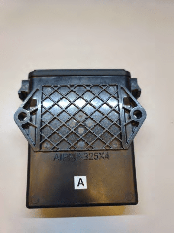
JUP-SMSE013
Apr 16, 2024RFID Read/Writer for Chemical and Fertilizer application system
Equipment Class
DSS - Part 15 Spread Spectrum Transmitter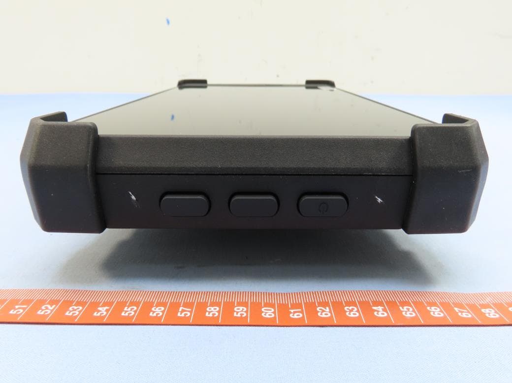
JUP-TD540
Jul 17, 202210 inch Touch Display
Equipment Class
DXX - Part 15 Low Power Communication Device Transmitter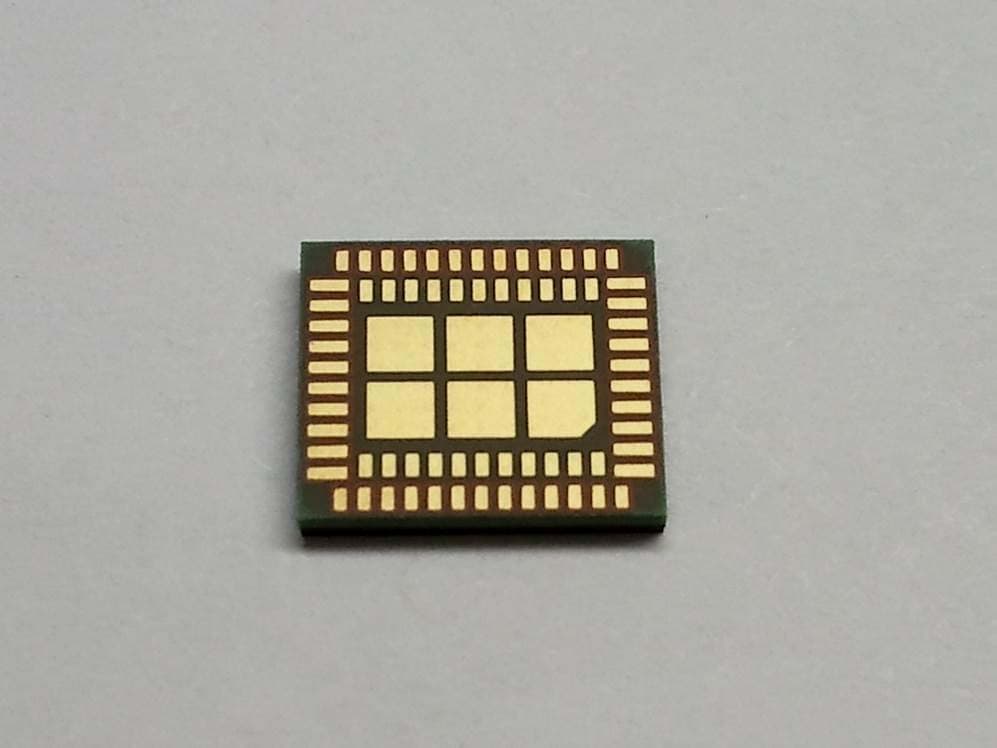
JUP-95807WFBT
Sep 14, 2014WLAN+ Bluetooth Combo Module
Equipment Class
DSS - Part 15 Spread Spectrum Transmitter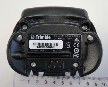
JUP88161
Oct 20, 2013GeoExplorer(R) 7 Series handheld, Geo 7X
Equipment Class
DTS - Digital Transmission System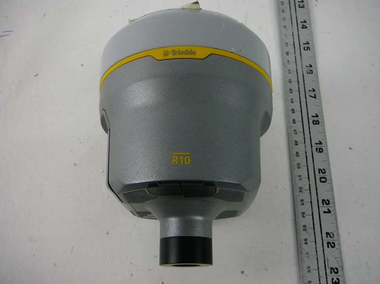
JUP-9090991
Jul 25, 2012GPS Receiver + 900 MHz + Wi-Fi + Bluetooth Radio
Equipment Class
DSS - Part 15 Spread Spectrum Transmitter