JUP-7486-CIRAAGPS data transceiver
Trimble, Inc.
Click to zoom
Application Details
- Equipment Class
- DXX - Part 15 Low Power Communication Device Transmitter
- Date of Grant
- May 08, 2000
- Application Purpose
- Original Equipment
- Date of Application
- Apr 13, 2000
- Equipment Note
- GPS data transceiver
- Frequency Range
- 916.55000000 - 916.55000000
- Company
- Trimble, Inc.
- Country
- United States
Documents & Files
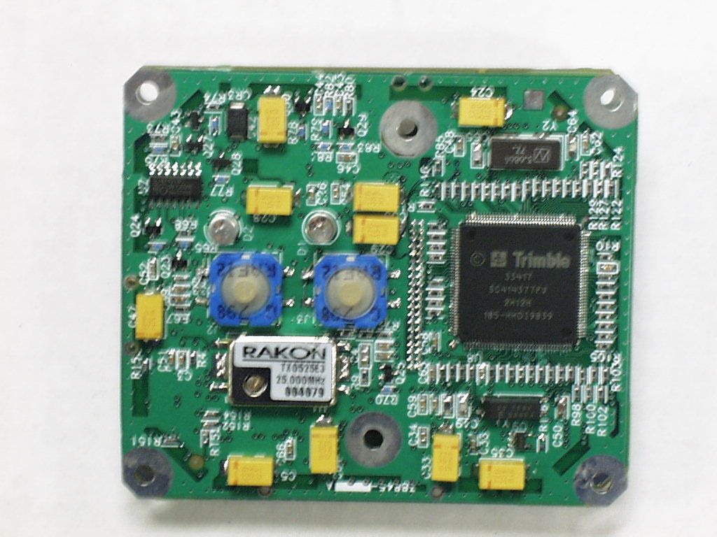
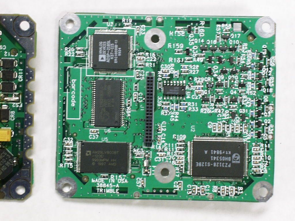
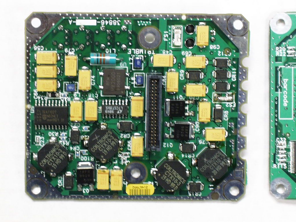
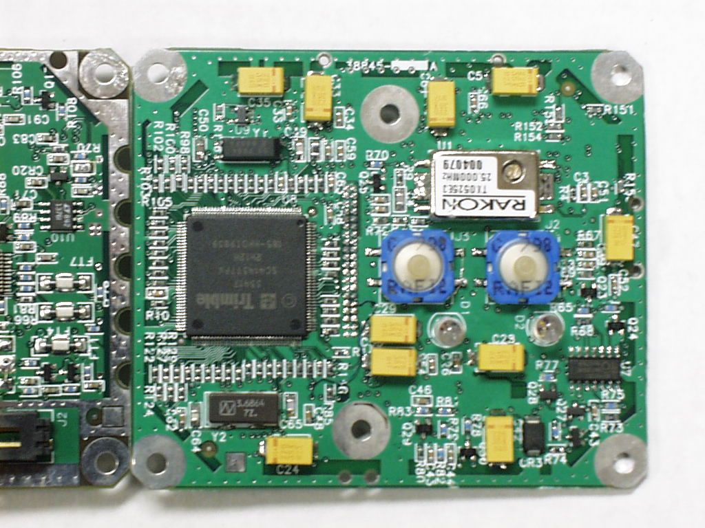

Document Text
Text extracted from the exhibit documents filed with the FCC. Open a document above to read the original.
Users Manual
BoB (Beacon On a Belt) USER’S MANUAL Draft Only Revision 0.10 April 3, 2000 Copyright Copyright © 1998-1999 Trimble Navigation Limited. All rights reserved. No part of this manual may be copied, photocopied, reproduced, translated, or reduced to any electronic medium or machine-readable form without prior written consent from Trimble Navigation Limited BoB Product Requirements Specification26 February 1999 Trimble Company Confidential Issue : 1.10 J:\BoB\PRS\BoB PRS110.doc 2 CONTENTS 1. System Description....................................................................................................... 3 1.1User Features.......................................................................................................... 3 1.2System Operation.................................................................................................... 4 1.2.1Modes of Operation ..................................................................................................................4 1.3User Interface ......................................................................................................... 6 1.3.1LED interface............................................................................................................................6 1.3.2Button Control...........................................................................................................................8 1.3.3Displaying and Changing the BoB Configuration ......................................................................9 1.3.4Transmission of Data from a Datalogger...................................................................................9 1.3.5Best Mode station tracking......................................................................................................10 1.3.6Firmware upgrade...................................................................................................................10 1.3.7Keypad/Display ......................................................................................................................10 1.4BoB Sub Systems.................................................................................................. 11 1.4.2Mechanical..............................................................................................................................12 1.4.3Configuration Manager Software ............................................................................................13 1.4.4Data Backup Scheme...............................................................................................................13 2. Additional Information.............................................................................................. 14 2.1Warranty Information........................................................................................... 14 2.2Coast Guard MSK Signals .................................................................................... 14 2.3RTCM Message Support....................................................................................... 14 2.4Integrity Monitoring.............................................................................................. 14 BoB Product Requirements Specification26 February 1999 Trimble Company Confidential Issue : 1.10 J:\BoB\PRS\BoB PRS110.doc 3 1. System Description 1.1 User Features The following table identifies the operational features for BoB. ITEMSPECIFICATIONNOTES Beacon Receiver AntennaBuilt-inOmni-directional Beacon AlmanacBoB must store the last recorded beacon almanac. This is to be updated whenever a more recent almanac is received Beacon Channel trackingTracks 2 channels simultaneously Wireless LinkTransmitter only, license free frequency band. Must be able to be used in any location where the user is capable of receiving beacon correction data. Must be enabled/disabled by Firmware, or permanently disabled at build time. 900Mcs transmitter primarily for use in the USA. ConfigurationMust be ready ‘out of the box’ Also via PC based software. Two-button UI Battery LifeAt the least the same or better on single charge. Regular day shift. External Antenna support External antenna support is NOT required Wireless link5 foot specTypical operational range Operational IndicationsMinimum of power status and Beacon tracking status. RTCM capabilitySC-104, version 2Output in standard format on cabled serial connection, supportable by any product with RTCM input ability. Operational ModesBest and Fixed Firmware UpgradeSerial port connection.User can upgrade. ErgonomicEasy to get into and out of vehicles with no requirement to detach and re-attach. Comfortable and light to wear on hip. Standard AccessoriesMust be supplied with a pouch that enables the user to access the buttons. simple nylon belt with plastic buckle (similar to the hip pack shoulder strap). Cable for connection to PC (Null Modem) The pouch padded to the users hip from the unit. This will probably be dependent on the final weight and shape of the product. Optional AccessoriesVehicle kits will be available.Not necessarily in time for release. BoB Product Requirements Specification26 February 1999 Trimble Company Confidential Issue : 1.10 J:\BoB\PRS\BoB PRS110.doc 4 1.2 System Operation 1.2.1 Modes of Operation BoB will track frequencies using one of two modes: Best and Fixed. The list of frequencies that can be tracked, plus the startup mode, can be controlled using PC-BoB software. Normally users will either have a very short include list (e.g. one to five stations) or will have a very long include list (excluding only one or two dominant stations). Those with a short list will operate either in Best or Fixed mode depending on their situation, however those with a very long list will usually always be in Best mode. 1.2.1.1 Best When BoB is in Best mode it will track the best frequency that it can, and will change frequencies if its current frequency becomes unsatisfactory. The algorithm for determin…
Text truncated - open the document above for the full version.
Cover Letter(s)
tel: 650-726-1263 fax: 650-726-1252 internet: [email protected] Thomas N. Cokenias EMC & Radio Type Approvals Test & Consulting Services for Commercial, Military, International Compliance P.O. Box 1086 El Granada, CA 94018 14 April 2000 FCC Laboratory 7435 Oakland Mills Road Columbia, MD 21046 Attention: Application Examiner Reviewing Engineer Re: Request for confidentiality per Section 0.459 of FCC Rules Applicant: Trimble Navigation FCC ID: JUP-7486-CIRAA To whom it may concern, Request is hereby submitted, on behalf of my client Trimble Navigation, to withhold from public review certain portions of the application for equipment certification for the referenced FCC identifier. In particular, the following sections of the application and report are requested to be kept confidential: Schematics Block diagrams Theory of operation Rationale for request for confidentiality: Trimble Navigation has invested considerable time and materials in research and development to produce the referenced product. Disclosure of the confidential portions of this application to competitors would give them competitive advantage in developing similar products. The $135 fee for confidentiality has been submitted along with the fee for certification. If you have questions or need further information, please contact the undersigned. Sincerely, THOMAS N. COKENIAS EMC Consultant/Agent for Trimble Navigation. tel: 650-726-1263 fax: 650-726-1252 internet: [email protected]
ID Label/Location Info
FCC ID Label Format and Location: FCC ID: JUP-7486-CIRAA This device complies with Part 15 of the FCC Rules. Operation is subject to the following two conditions: (1) this device may not cause harmful interference, and (2) this device must accept any interference received, including interference that may cause undesired operation.
Test Report
Sheet4 COMPLIANCE ENGINEERING SERVICES, INC. Harmonic Emissions 3/17/00 15.249(a) Juan MartinezA site (1.0 Meter) Trimble(BOB)f o= 916.2 MHz F(MHz) READING AF CL AMP DIST HPF TOTAL LIMIT MARGIN (dBuV) (dB) (dB) (dB) (dB) (dB) (dBuV/m) (dBuV/m) (dB) Pk Avg Pk Avg Pk Avg Pk Avg 2794 51.9 46.8 29 3.62 -42.17 -15.5 1 27.85 22.75 74 54 -46.2 -31.3 3665 44.29 31.8 5.03 -42.02 -9.5 1 30.6 54 -23.4 4582 43.42 32 5.63 -41.78 -9.5 1 30.77 54 -23.2 5498 44.27 31.2 6.03 -41.65 -9.5 1 31.35 54 -22.7 6414 43.79 34 6.63 -41.52 -9.5 1 34.4 54 -19.6 7330 48 37 7.03 -41.43 -9.5 1 42.1 54 -11.9 8246 48.69 37.1 8.04 -39.8 -9.5 1 45.53 54 -8.47 9162 45.54 38 8.44 -39.4 -9.5 1 44.08 54 -9.92 NOTE: ALL READINGS ARE VERTICAL ANALYZER SETTINGS DIST : Correction to extrapolate reading to 3m specification distance Res bw Avg. bw 1.5ft measurement distance: -15.56 dB PEAK(Pk ) : 1MHz 1MHz AVERAGE(Avg): 1MHz 10Hz AF : Antenna Factor AMP : Pre-amp gain CL : Cable loss HPF : High pass filter insertion loss (1.802GHz) FSY (S/N: 001) Page 1
Test Report
000317A1 3/17/00 8:23 AM Juan Martinez Trimble Transmitter (M/N: Bob Eut only 15.249 TX tt Freq. ReadingAFCLOSS Pre-Am pLevelLimitMarginPolAzHeightMark (Mhz)(dBuV)(dB)(dB)(dB) (dBuV/m )FCC_B(dB)(H/V)(Deg)(Meter)(P/Q/A) 916.5556.8021.4664.700.0082.9694.00-11.043mH180.001.50P 1832.00 23.7928.6927.300.0059.7874.00-14.223mH180.001.10P 1833.00 13.4228.6837.300.0049.4054.00-4.603mH180.001.20Av 1833.00 25.7128.7717.300.0061.7874.00-12.223mV270.001.10P 1833.00 14.5928.7717.300.0050.6654.00-3.343mV270.001.10Av Total #:6 Compliance Certification Services 1366 Bordeaux Drive Sunnyvale, CA 95037 Tel: (408) 752-8166 Fax: (408) 752-8168 Project #: Report #: Date& Time: Test Engr: Company: EUT Description: Test Configuration : Type of Test: Mode of Operation: FCC_A !"#$% FCC_B !"#$%& EN_A !"#$% EN_B !"#$% Pre-amp '()*+
Test Report
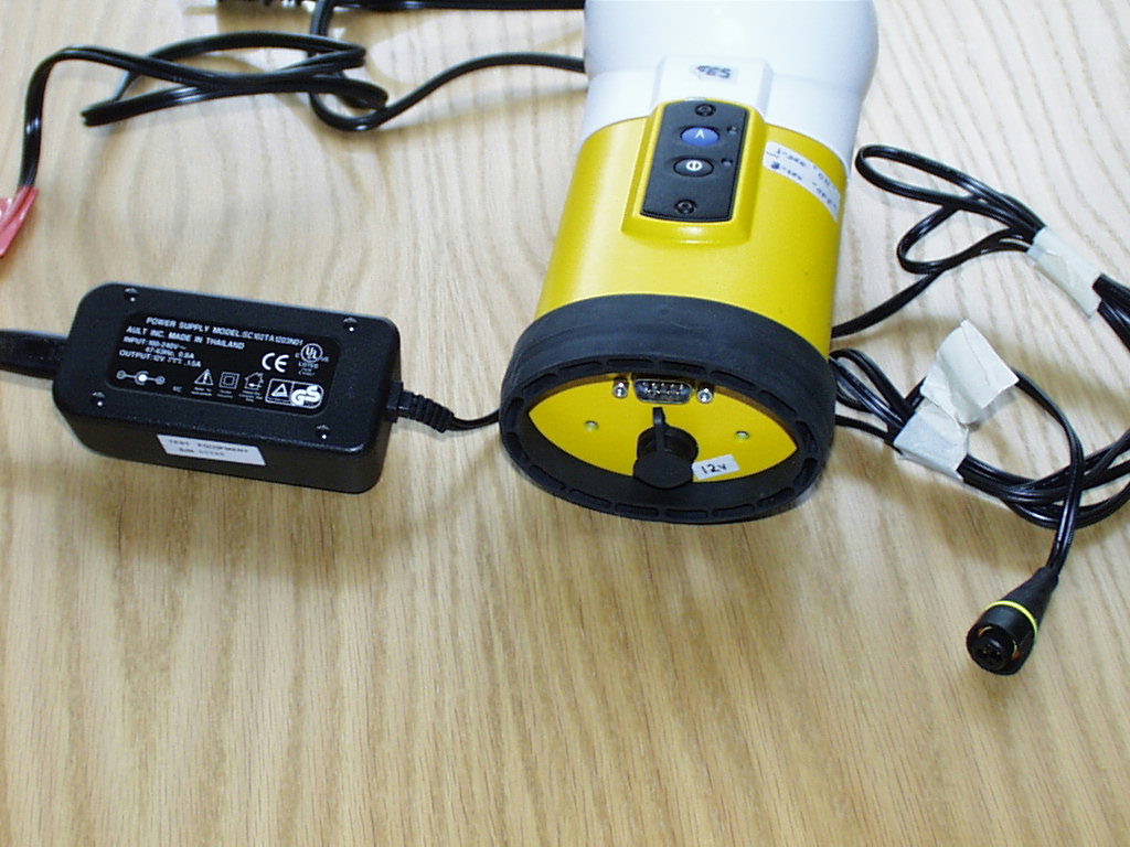
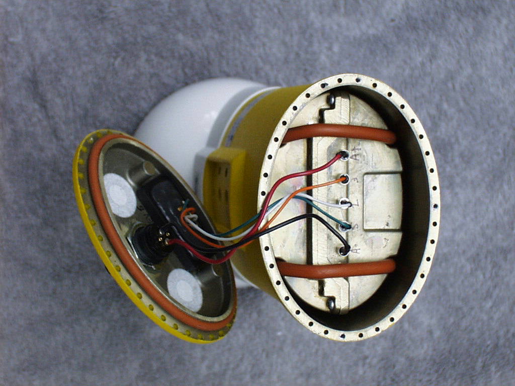
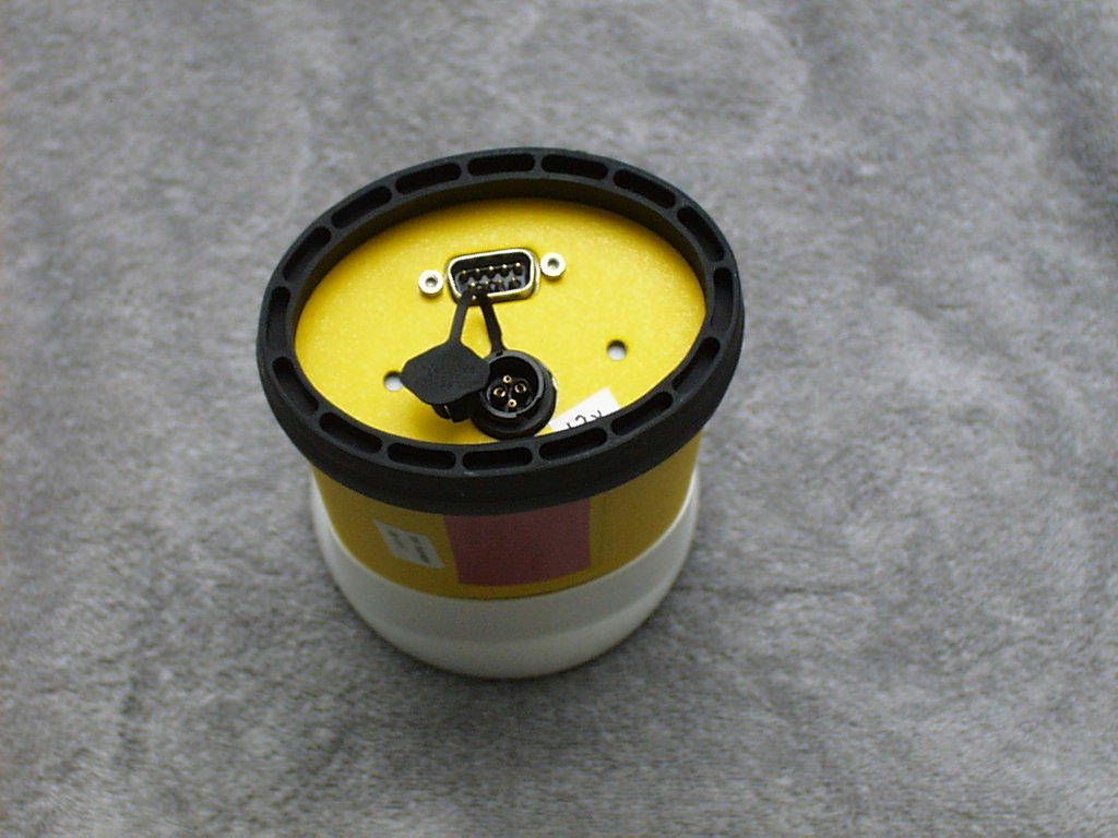
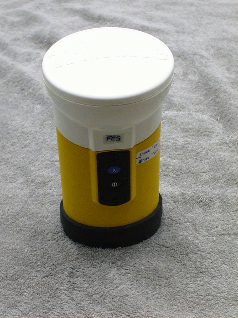
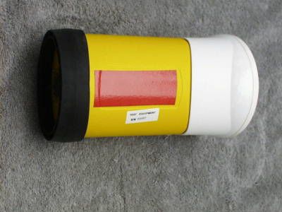
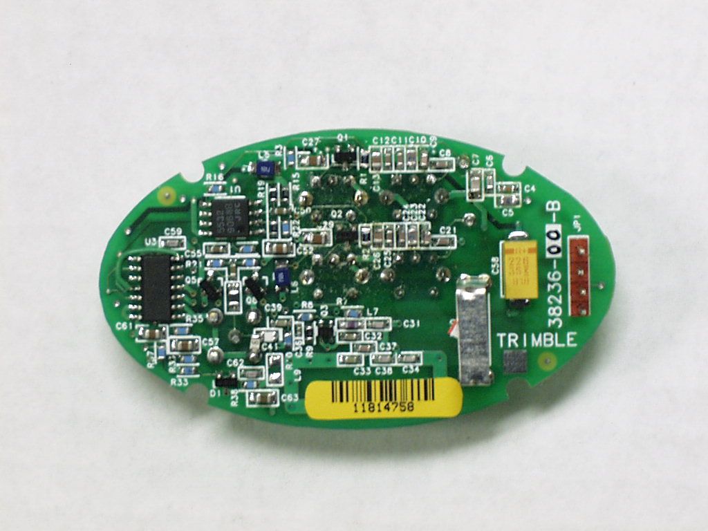
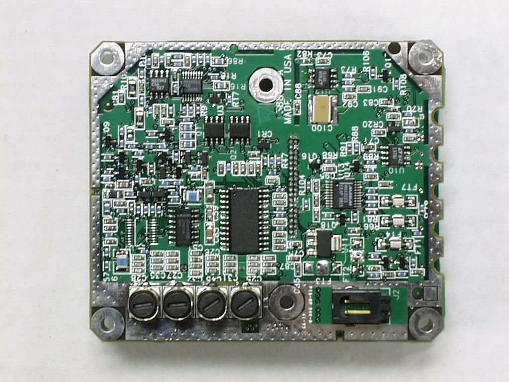
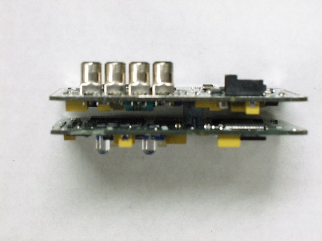
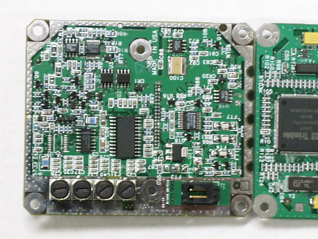
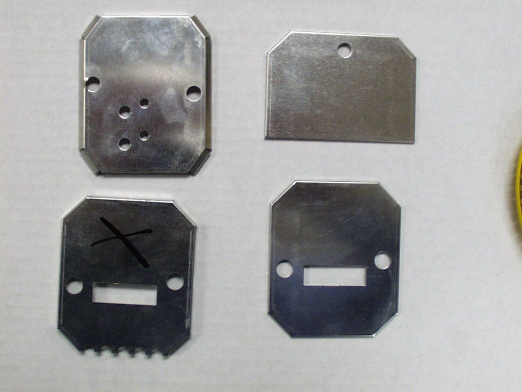
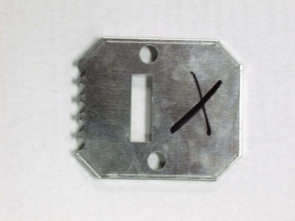
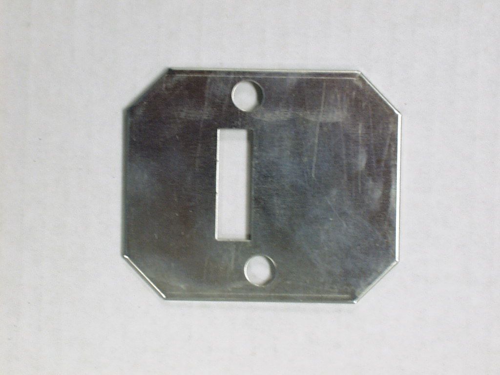
tel: 650-726-1263 fax: 650-726-1252 internet: [email protected] JUP-7486-CIRAA page 1 of 14 pages BoB Thomas N. Cokenias EMC/RFI Specialist Test & Consulting Services for Commercial, Military, International Compliance P.O. Box 1086 El Granada CA 94018 CERTIFICATION TEST REPORT FOR A 916.55 MHz TRANSCEIVER Applicant: Trimble Navigation Ltd. 645 N. Mary Avenue Sunnyvale, CA 94086 Model:"BoB" FCC ID:JUP-7486-CIRAA Operating Frequency:916.55 MHz Fixed Rule Part:15.249 Used For:Short range GPS data distribution Power Source:Internal rechargeable batteries Test Location:Compliance Consulting Services 951F Monterey Road Morgan Hill, CA 95087 All tests were performed by me or under my supervision. The Trimble low power transceiver meets all emissions requirements in FCC Part 15. THOMAS N. COKENIAS14 April 2000 tel: 650-726-1263 fax: 650-726-1252 internet: [email protected] JUP-7486-CIRAA page 2 of 14 pages BoB EXHIBITS EXHIBIT A: Product Photographs EXHIBIT B: Label Drawing EXHIBIT C: User Manual EXHIBIT D: Theory of Operation (Confidentiality Requested) EXHIBIT E: Report of Measurements EXHIBIT F: Schematics (Confidentiality Requested) EXHIBIT G: Block Diagram (Confidentiality Requested) tel: 650-726-1263 fax: 650-726-1252 internet: [email protected] JUP-7486-CIRAA page 3 of 14 pages BoB EXHIBIT A:Product Photographs - refer to separate jpg attachments tel: 650-726-1263 fax: 650-726-1252 internet: [email protected] JUP-7486-CIRAA page 4 of 14 pages BoB EXHIBIT B:Label Drawing - refer to separate Word attachment tel: 650-726-1263 fax: 650-726-1252 internet: [email protected] JUP-7486-CIRAA page 5 of 14 pages BoB EXHIBIT C:User Manual - refer to separate Word attachment tel: 650-726-1263 fax: 650-726-1252 internet: [email protected] JUP-7486-CIRAA page 6 of 14 pages BoB EXHIBIT D:Theory of Operation (Confidentiality Requested) - refer to separate Word attachment tel: 650-726-1263 fax: 650-726-1252 internet: [email protected] JUP-7486-CIRAA page 7 of 14 pages BoB EXHIBIT E: Report of Measurements - refer to separate Word attachment tel: 650-726-1263 fax: 650-726-1252 internet: [email protected] JUP-7486-CIRAA page 8 of 14 pages BoB EXHIBIT F: Schematics (Confidentiality Requested) - refer to separate JPEG attachments tel: 650-726-1263 fax: 650-726-1252 internet: [email protected] JUP-7486-CIRAA page 9 of 14 pages BoB EXHIBIT G: Block Diagram (Confidentiality Requested) - refer to separate JPEG attachments tel: 650-726-1263 fax: 650-726-1252 internet: [email protected] JUP-7486-CIRAA page 10 of 14 pages BoB TEST PROCEDURES Radiated Emissions Test Requirement: 15.205, 15.249 Measurement Equipment Used: HP 8593EM Spectrum Analyzer HP 8447 Preamplifier, .1 - 1300 MHz HP 8449 Preamplifier, 1-26.5 GHz Chase Bilog Antenna, 30 - 2000 MHz 150' low loss coax (site A standard) EMCO 3115 Double Ridged Horn antenna, 1 - 18 GHz 16 ft Flexco low loss cable (0.85 dB/ft at 26.5 GHz) Test Set-up, 30 - 2000 MHz Antenna mast Ground plane 1 - 4 meters 3 meters turntable, laptop computer preamplifier spectrum analyzer tel: 650-726-1263 fax: 650-726-1252 internet: [email protected] JUP-7486-CIRAA page 11 of 14 pages BoB Test Set-Up, 2000 - 9160 MHz Ground plane d: 1 ft - 1m d 1-2 meters EUT turntable horn antenna preamplifier AC Fig. 1 spectrum analyzer 1. The EUT was placed on a wooden table resting on a turntable on the open air test site. The search antenna was placed 3m from the EUT. The EUT antenna was mounted vertically as per normal installation. 2. The turntable was slowly rotated to locate the direction of maximum emission at each emission falling in the restricted bands of 15.205. 3. Once maximum direction was determined, the search antenna was raised and lowered in both vertical and horizontal polarizations. The maximum readings so obtained are recorded in the data listed below. Test Results: Refer to separate .xls attachments BoB Low F and BoB Hi F . tel: 650-726-1263 fax: 650-726-1252 internet: [email protected] JUP-7486-CIRAA page 12 of 14 pages BoB All emissions outside 902-928 MHz band were below 15.209 emissions limits. AC Line Conducted Emissions Test Requirement: 15.207 NOT APPLICABLE - EUT is used on a utility belt and is only connected to AC adapter for charging of internal batteries. THOMAS N. COKENIAS14 April 2000
Contact Information
Applicant
Tony Phan(Engineering Management, GNSS Core R&D)
Technical Contact
T.N. Cokenias ConsultingThomas N Cokenias
[email protected]650 726 1263
355 El Granada Blvd · El Granada, California · United States
Non-Technical Contact
T.N. Cokenias ConsultingThomas N Cokenias
[email protected]650 726 1263
Test Firm
Compliance Certification Services IncSteve Cheng
Technical Specifications
| # | Rule Parts | Frequency Range | Power Output | Emission |
|---|---|---|---|---|
| 1 | 15C | 916.55 MHz - 916.55 MHz | - | na |
Other Applications from Trimble, Inc.
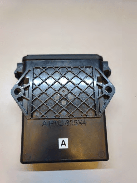
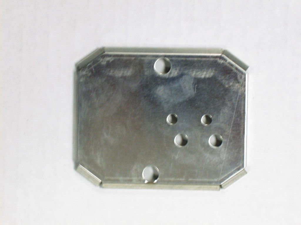
JUP-SMSE013
Apr 16, 2024RFID Read/Writer for Chemical and Fertilizer application system
Equipment Class
DSS - Part 15 Spread Spectrum Transmitter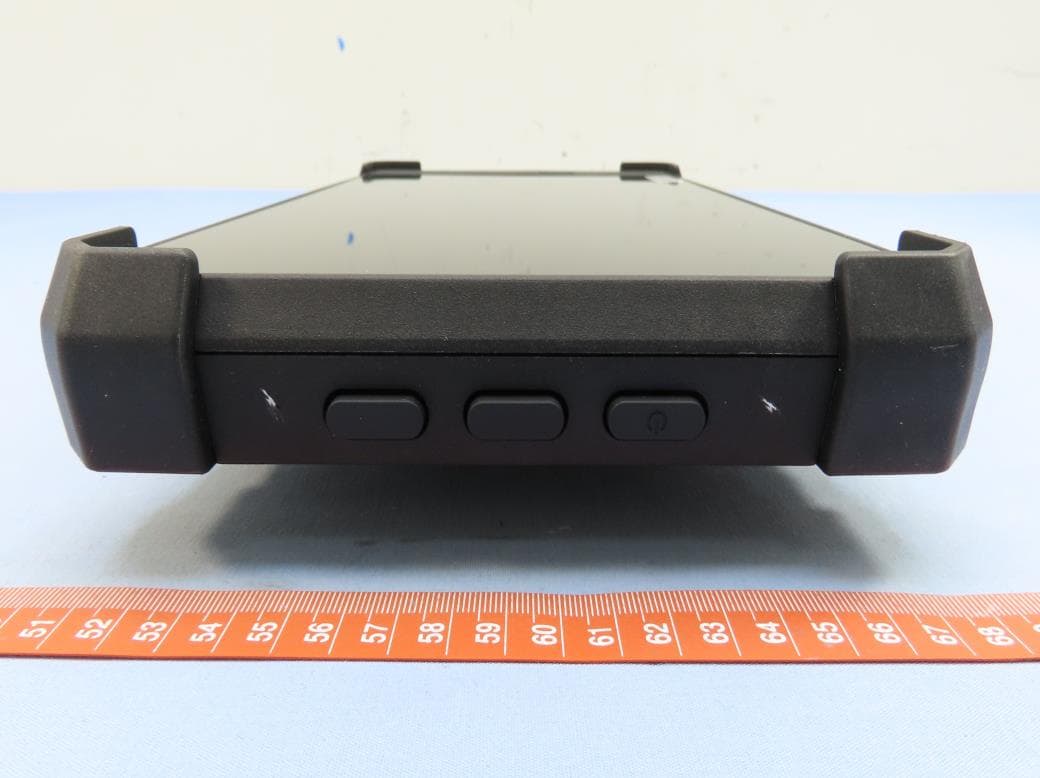
JUP-TD540
Jul 17, 202210 inch Touch Display
Equipment Class
DXX - Part 15 Low Power Communication Device Transmitter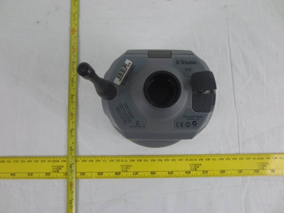
JUP-9091191
Jan 15, 2015GNSS Receiver+900 MHz+Wi-Fi+Bluetooth
Equipment Class
DSS - Part 15 Spread Spectrum Transmitter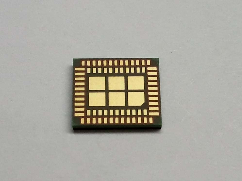
JUP-95807WFBT
Sep 14, 2014WLAN+ Bluetooth Combo Module
Equipment Class
DSS - Part 15 Spread Spectrum Transmitter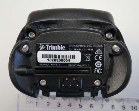
JUP88161
Oct 20, 2013GeoExplorer(R) 7 Series handheld, Geo 7X
Equipment Class
DTS - Digital Transmission System