JUP-WCDCM300GTelematics Radio Modem
Trimble, Inc.
Click to zoom
Application Details
- Equipment Class
- DTS - Digital Transmission System
- Date of Grant
- Jan 31, 2011
- Application Purpose
- Original Equipment
- Date of Application
- Jan 31, 2011
- Equipment Note
- Telematics Radio Modem
- Frequency Range
- 2412.00000000 - 2462.00000000
- Company
- Trimble, Inc.
- Country
- United States
Documents & Files
Document Text
Text extracted from the exhibit documents filed with the FCC. Open a document above to read the original.
Users Manual
INSTALLATION GUIDE Trimble ® DCM300 Telematics (This page intentionally left blank) INSTALLATION GUIDE Trimble ® DCM300 ™ Telematics Version 0.10 Revision C January 2011 Corporate Office Trimble Navigation Limited 935 Stewart Drive Sunnyvale, CA 94085 USA www.trimble.com Construction Services Group Trimble Navigation Limited Construction Services Group 10355 Westmoor Drive, Bldg. 100 Westminster, CO 80021 USA 800-538-7800 (toll free in USA) +1-937-245-5600 Phone +1-937-233-9004 Fax www.trimble.com E-mail: [email protected] Legal Notices © 2010, Trimble Navigation Limited. All rights reserved. Trimble, and the Globe & Triangle logo are trademarks of Trimble Navigation Limited, registered in the United States Patent and Trademark Office and in other countries. All other trademarks are the property of their respective owners. Release Notice This is the November 2010 release (Revision A) of the DCM300 Telematics Installation Guide. Limited Warranty Terms and Conditions Product Limited Warranty Subject to the terms and conditions set forth herein, Trimble Navigation Limited (“Trimble”) warrants that for a period of (1) year from date of purchase this Trimble product (the “Product”) will substantially conform to Trimble's publicly available specifications for the Product and that the hardware and any storage media components of the Product will be substantially free from defects in materials and workmanship. Product Software Product software, whether built into hardware circuitry as firmware, provided as a standalone computer software product, embedded in flash memory, or stored on magnetic or other media, is licensed and not sold. If accompanied by a separate end user license agreement, use of any such software will be subject to the terms of such end user license agreement (including any differing limited warranty terms, exclusions and limitations), which shall control over the terms and conditions set forth in this limited warranty). Software Updates During the limited warranty period you will be entitled to receive such Fix Updates and Minor Updates to the Product software that Trimble releases and makes commercially available and for which it does not charge separately, subject to the procedures for delivery to purchasers of Trimble products generally. If you have purchased the Product from an authorized Trimble distributor rather than from Trimble directly, Trimble may, at its option, forward the software Fix Update or Minor Update to the Trimble distributor for final distribution to you. Major Upgrades, new products, or substantially new software releases, as identified by Trimble are expressly excluded from this update process and limited warranty. Receipt of software updates shall not serve to extend the limited warranty period. For purposes of this warranty the following definitions shall apply: “Fix Update” means an error correction or other update created to fix a previous software version that does not substantially conform to its published specifications; (2) “Minor Update” occurs when enhancements are made to current features in a software program; and (3) “Major Upgrade” occurs when significant new features are added to software, or when a new product containing new features replaces the further development of a current product line. Trimble reserves the right to determine, in its sole discretion, what constitutes a significant new feature and Major Upgrade. Warranty Remedies If the Trimble Product fails during the warranty period for reasons covered by this Limited Warranty and you notify Trimble of such failure during the warranty period, Trimble at its option will repair OR replace the nonconforming Product, OR refund the purchase price paid by you for the Product, upon your return of the Product to Trimble in accordance with Trimble's standard return material authorization procedures. How to Obtain Warranty Service To obtain warranty service for the Product, please contact your Trimble Construction Services dealer. Alternatively, you may contact Trimble to request warranty service at 1-888-801-4363 (toll free) or 1-720-457-0189 (24 hours a day) or e-mail your request to [email protected]. Please be prepared to provide: – your name, address, and telephone numbers – proof of purchase –this Trimble warranty card –a description of the nonconforming Product including the model number – an explanation of the problem. The customer service representative may need additional information from you depending on the nature of the problem. Warranty Exclusions and Disclaimer This Product limited warranty shall only apply in the event and to the extent that (i) the Product is properly and correctly installed, configured, interfaced, maintained, stored, and operated in accordance with Trimble's applicable operator's manual and specifications, and; (ii) the Product is not modified or misused. This Product limited warranty shall not apply to, and Trimble shall not be responsible for defects or performance problems resulting from (i) the combination or utilization of the Product with hardware or software products, information, data, systems, interfaces or devices not made, supplied or specified by Trimble; (ii) the operation of the Product under any specification other than, or in addition to, Trimble's standard specifications for its products; (iii) the unauthorized, installation, modification, or use of the Product; (iv) damage caused by: accident, lightning or other electrical discharge, fresh or salt water immersion or spray; or exposure to environmental conditions for which the Product is not intended; or (v) normal wear and tear on consumable parts (e.g., batteries). Trimble does not warrant or guarantee the results obtained through the use of the Product. NOTICE REGARDING PRODUCTS EQUIPPED WITH TECHNOLOGY CAPABLE OF TRACKING SATELLITE SIGNALS FROM SATELLITE BASED AUGMENTATION SYSTEMS (SBAS) (WAAS/EGNOS, AND MSAS), OMNISTAR, GPS, MODERNIZED GPS, OR GLONASS SATELLITES,…
Text truncated - open the document above for the full version.
Cover Letter(s)
DCM300C Wi2Wi Engineering Statement – Bluetooth Disabled Trimble Heavy & Highway. Proprietary and Confidential 1/10/2011 Revision 01 1 Trimble DCM300G Wi2Wi module: Bluetooth Radio Disabled Topic: Bluetooth disabled in W2CBW009Di radio module Trimble’s DCM300G, uses Wi2Wi W2CBW009Di module for wifi communications. The module’s Bluetooth ability is not a feature in the commercial release of this product. DCM300G application firmware does not initialize the Bluetooth radio component and the Bluetooth device driver will not be loaded in production code releases. Customer application firmware will not enable or include Bluetooth radio component, preventing users from being able to enable the Bluetooth radio feature themselves. Max Collins Trimble Navigation
Cover Letter(s)
RFI Global Services Ltd Pavilion A, Ashwood Park, Ashwood Way, Basingstoke, Hampshire, RG23 8BG Tel: +44 (0) 1256 312000 Fax: +44 (0) 1256 312001 Email: [email protected] Website: www.rfi-global.com Registered in England and Wales Company number: 2117901 FCC ID: JUP-WCDCM300G This confirms the applicability of 15 247 Report 1 for WIFI module W2CBW009-D, together with DCM300G 15 247 Report 2 and DCM300G 15 247 Report 3 to demonstrate the requirements of Part 15.247 for the FCC ID: JUP-WCDCM300G using antenna types Mobilemark RM3-2400 and Pulse NMO5E2400B. FCC ID: JUP-WCDCM300G uses the same WIFI module W2CBW009-D together with the antennas listed above, as that used in FCC ID: W2CBW009-C. The applicant has also confirmed the listed antennas comply with Part 15.203 Antenna Requirement. Test Reports 15 247 Report 1 - BACL R10032233-247 - FCC ID: U9R-W2CBW009DI 15 247 Report 2 - RFI-RPT-79038JD03A (26 January 2011) - FCC ID: JUP-WCDCM300C 15 247 Report 3 - RFI-RPT-79038JD11A (25 January 2011) - FCC ID: JUP-WCDCM300C RFI Global Services Ltd TCB
ID Label/Location Info
DCM300G Labeling Trimble Heavy & Highway. 1/31/2011 Revision 01 1 Trimble DCM300G Label 1. Purpose This document outlines all the requirements for the labels to be used on Torch. This document only applies to labels that have unique or required information on them. 2. Label Locations There will be two labels placed on the Torch enclosure. The first label will be the Branding Label. The purpose of this label is to provide all serialized information programmed into the device and the part number of the device. The branding label will be applied to the back of the enclosure in the location outlined in figures 1. The branding label may have different formats and information depending on the branding requirements. The 2D barcode on the branding label will contain a digital copy of all the serialized information represented in human readable format on the branding label. The second label will be the International Certification Label and will be applied to the location outline in figure 1. The certification label will contain all the information required for world certification for the torch enclosure. Example illustration of label used on Trimble DCM300G Branding Label Label stock Trimble PN: 88980 Figure 1: Example illustration of a label used on DMC300G DCM300G Labeling Trimble Heavy & Highway. 1/31/2011 Revision 01 2 International Certification Label Label Stock Trimble PN: 82460 The International certification label is used for any country specific certification marks and information. This label will only be used on DCM300G models. Figure 2: Example of reserved space on the certification label for country approval marking requirements
Internal Photos
Wi2Wi, Inc. FCC ID: U9R-W2CBW009DI Report Number: R1003233-247 Page 83 of 83 FCC Part 15.247 Test Report 18.5 EUT without shielding View ***** END OF REPORT *****
RF Exposure Info
Page 1 of 4 Trimble Navigation Limited 25 January 2011 10355 Westmoor Drive, Suite 100 Westminster, Colorado 80021 USA MPE Calculation for (GSM/ UMTS) DCM300G - OET Bulletin 65 FCC ID: JUP-WCDCM300G The FCC requires that the calculated MPE be equal to or less than a given limit dependent on frequency at a distance of 20 cm from a device to the body of a user. The transmitter operation for the DCM300G covers GSM850 and PCS1900 and 2.4GHz WIFI operating bands. The following FCC Rule Parts are applicable: Part 1.1310 – Radiofrequency radiation exposure limits Part 2.1091(c) – Radiofrequency radiation exposure evaluation: mobile devices Part 24.232 (b) Mobile/ Portable stations are limited to 2 Watts EIRP peak power Part 22.913 (a)(2) The ERP of mobile transmitters and auxiliary test transmitters must not exceed 7 Watts. The MPE calculation as given in FCC OET Bulletin 65, page 19 is used to calculate the safe operating distance for the user. S = EIRP/4 π R 2 Where S = Power density EIRP = Effective Isotropic Radiated Power (EIRP = P x G) P = Conducted Transmitter Power G = Antenna Gain (relative to an isotropic radiator) R = distance to the centre of radiation of the antenna For GSM 850 Transmitter frequency range = 824MHz to 849MHz Max. measured conducted transmitter power = 31.7dBm (1.48W) For Class 10 GPRS with 2 uplink time slots (2/8) Power = 2/8 x 1.48 = 0.37W Page 2 of 4 MPE Requirement From table 1 (b) - Limits for General Population/ Uncontrolled Exposure of FCC Rule Part 1.1310 for GSM850 S = f/1500 mW/cm 2 (f = operating frequency) S = 824/1500 = 0.55 mW/cm 2 (worst case) MPE Calculation to Determine Safe Maximum Antenna Gain (G) Values: S = 0.55 mW/cm 2 P = 370mW R = 20cm S = PxG/4 π R 2 0.55 = 370xG/(12.56 x 20 2 ) 0.55 x (12.56 x 20 2 ) = 370 x G 0.55 x (12.56 x 20 2 )/ 370 = G G = 7.46 (8.7dBi) Calculation for Maximum radiated power output Maximum antenna gain G that can be used to comply with the maximum transmitter power limit of 7W ERP of Part 22.913 (a)(2) is calculated as: For ERP = 7W limit (38.45dBm) ERP = EIRP – 2.1dB (half wave dipole gain) EIRP = 38.45 + 2.1 = 40.55dBm = 11.35W So for max gain antenna permitted (G) : EIRP = P x G P conducted =1.48W ie: 11.35 = 1.48 x G G = 7.66 (8.8dBi) For GSM850 maximum antenna gain is therefore limited to 8.7dBi by MPE requirements. Page 3 of 4 For PCS1900 Transmitter frequency range = 1850MHz to 1910MHz Max. measured conducted transmitter power P = 28.6dBm (0.724W) MPE Requirement From table 1 (b) - Limits for General Population/ Uncontrolled Exposure of FCC Rule Part 1.1310 for PCS1900 S = 1.0 mW/cm 2 (worst case) MPE Calculation to Determine Safe Maximum Antenna Gain (G) Values: S = 1.0 mW/cm 2 P = 724mW R = 20cm S = PxG/4 π R 2 1.0 = 724xG/(12.56 x 20 2 ) 1.0 x (12.56 x 20 2 ) = 724 x G 1.0 x (12.56 x 20 2 )/ 724 = G G = 6.94 (8.4dBi) Calculation for Maximum radiated power output Maximum antenna gain G that can be used to comply with the maximum transmitter power limit of 2W EIRP of Part 24.232(b) is calculated as: P x G = 2 P conducted =0.724W ie: G = 2/0.724 = 2.76 (4.4dBi) For PCS1900 maximum antenna gain is therefore limited to 4.4dBi by FCC Rule 24.232(b) EIRP for maximum permitted transmitter power. Page 4 of 4 For 2.4GHz band Transmitter frequency range = 2412 – 2462MHz band Max. measured Transmitter EIRP = 20.6dBm max using 5dBi gain antenna MPE Requirement From table 1 (b) - Limits for General Population/ Uncontrolled Exposure of FCC Rule Part 1.1310 for 2.4GHz S = 1.0 mW/cm 2 (worst case) MPE Calculation Using 5.0dBi max Gain Antenna Values: PG (EIRP) = 20.6dBm (115mW) R = 20cm S = PxG/4 π R 2 S = 115/ (12.56 x 20 2 ) = 115/ 5024 S = 0.023 This is within the required S = 1.0 mW/ cm 2 requirement. Conclusion The DCM300G complies with FCC Rule Part 1.1310 using a 5.0dBi gain antenna in the 2.4GHz WIFI band. FCC Rule Part 1.1310 and ERP Part 22.913 (a)(2), EIRP Part 24.232 (b) maximum transmitter power limits will not be exceeded for the DCM300G with antenna gains, including cable loss not exceeding 8.7dBi (850MHz) and 4.4dBi (1900MHz) respectively.
Test Report
TEST REPORT FROM RFI GLOBAL SERVICES LTD Test of: Torch DCM300G FCC ID:JUP-WCDCM300G To: FCC Parts 22.913 & 24.232 Test Report Serial No: RFI-RPT-RP77996JD05B This Test Report Is Issued Under The Authority Of Chris Guy, Head of Global Approvals: Checked By: Ian Watch Signature: Date of Issue: 26 January 2011 This report is issued in Adobe Acrobat portable document format (PDF). It is only a valid copy of the report if it is being viewed in PDF format with the following security options not allowed: Changing the document, Selecting text and graphics, Adding or changing notes and form fields. This report may not be reproduced other than in full, except with the prior written approval of RFI Global Services Ltd. The results in this report apply only to the sample(s) tested. TEST REPORT SERIAL NO: RFI-RPT-RP77996JD05B VERSION 1.0 ISSUE DATE: 26 JANUARY 2011 Page 2 of 21 RFI Global Services Ltd This page has been left intentionally blank. TEST REPORT SERIAL NO: RFI-RPT-RP77996JD05B VERSION 1.0 ISSUE DATE: 26 JANUARY 2011 RFI Global Services Ltd Page 3 of 21 Table of Contents 1. Customer Information .................................................................................................................. 4 2. Summary of Testing ..................................................................................................................... 5 2.1. General Information 5 2.2. Summary of Test Results 5 2.3. Methods and Procedures 5 2.4. Deviations from the Test Specification 5 3. Equipment Under Test (EUT) ....................................................................................................... 6 3.1. Identification of Equipment Under Test (EUT) 6 3.2. Description of EUT 6 3.3. Modifications Incorporated in the EUT 6 3.4. Additional Information Related to Testing 7 3.5. Support Equipment 9 4. Operation and Monitoring of the EUT during Testing ............................................................. 10 4.1. Operating Modes 10 4.2. Configuration and Peripherals 10 5. Measurements, Examinations and Derived Results ................................................................ 11 5.1. General Comments 11 5.2. Test Results: Part 22 - GSM850 12 5.2.1. Transmitter Output Power (ERP) 12 5.3. Test Results: Part 22 – UMTS FDD V 14 5.3.1. Transmitter Output Power (ERP) 14 5.4. Test Results: Part 24 - PCS 1900 16 5.4.1. Transmitter Output Power (EIRP) 16 5.5. Test Results: Part 24 – UMTS FDD II 18 5.5.1. Transmitter Output Power (EIRP) 18 6. Measurement Uncertainty .......................................................................................................... 20 Appendix 1. Test Equipment Used ................................................................................................ 21 TEST REPORT SERIAL NO: RFI-RPT-RP77996JD05B VERSION 1.0 ISSUE DATE: 26 JANUARY 2011 Page 4 of 21 RFI Global Services Ltd 1. Customer Information Company Name: Trimble Navigation Ltd Address: 10355 Westmoor Dr Westminster Colo 80021 United States TEST REPORT SERIAL NO: RFI-RPT-RP77996JD05B VERSION 1.0 ISSUE DATE: 26 JANUARY 2011 RFI Global Services Ltd Page 5 of 21 2. Summary of Testing 2.1. General Information Specification Reference: 47CFR22 Specification Title: Code of Federal Regulations Volume 47 (Telecommunications) 2010: Part 22 Subpart H (Public Mobile Services) – Section 22.913 Specification Reference: 47CFR24 Specification Title: Code of Federal Regulations Volume 47 (Telecommunications) 2010: Part 24 Subpart E (Personal Communication Services) – Section 24.232 Site Registration: FCC: 209735 Location of Testing: RFI Global Services Ltd, Wade Road, Basingstoke, Hampshire, RG24 8AH Test Date: 11 January 2011 2.2. Summary of Test Results FCC Reference (47CFR) Measurement Result Part 22 Part 22.913(a) Transmitter Output Power (ERP) Part 24 Part 24.232 Transmitter Output Power (EIRP) Key to Results = Complied = Did not comply 2.3. Methods and Procedures Reference: ANSI/TIA-603-D-2010 Title: Land Mobile Communications Equipment, Measurements and Performance Standards 2.4. Deviations from the Test Specification For the measurements contained within this test report, there were no deviations from, additions to, or exclusions from the test specification identified above. TEST REPORT SERIAL NO: RFI-RPT-RP77996JD05B VERSION 1.0 ISSUE DATE: 26 JANUARY 2011 Page 6 of 21 RFI Global Services Ltd 3. Equipment Under Test (EUT) 3.1. Identification of Equipment Under Test (EUT) Brand Name: Trimble Navigation Model Name or Number: Torch DCM300G IMEI: 354114012493061 Hardware Version Number: A Software Version Number: 0.1.5 FCC ID: JUP-WCDCM300G 3.2. Description of EUT The equipment under test was a data communications module (DCM) for use in construction vehicles. It contains a Cinterion HC25 module (FCC ID: QIPHC25) capable of GSM and UMTS and a Wi2Wi Wi-Fi module (FCC ID: U9R-W2CBW009DI) capable of 802.11b and 802.11g. The following antennas have been specified for use with the EUT: • Taoglas MA.104 “Hercules” Antenna, part number MA.104.C.A301111.B301311, declared antenna gain 0 dBi • Pulse IP67 Active 6 bands GPS Antenna, part number W4120GW5000, declared antenna gain 0 dBi • Wilson NMO Cellular Antenna /20 feet LMR-240 RF coaxial cable combination consisting of: Wilson NMO Cellular Antenna, part number 301104, declared antenna gain 4.9 dBi in the 800 MHz band and 5.9 dBi in the 1900 MHz band and 20 feet of type LMR-240 cable, part number GBR-20-240-T1-A. 3.3. Modifications Incorporated in the EUT No modifications were applied to the EUT during testing. TEST REPORT SERIAL NO: RFI-RPT-RP77996JD05B VERSION 1.0 ISSUE DATE: 26 JANUARY 2011 RFI Global Services Ltd Page 7 of 21 3.4. Additional Information Related to Testing Technology Tested: US Cellular (800 band) Mode: GSM/GPRS Maximum Output Power (ERP): GSM 33.05 dBm GPRS 33.05 dBm Transmit Frequency Range: 824 to 849 MHz Transmit Channels Tested: Channel ID Channel Number Channel Frequency (MHz) Bottom 128 824.2 Middle 190 836.6 Top 251…
Text truncated - open the document above for the full version.
Test Report
Note: This test report is prepared for the customer shown above and for the device described herein. It may not be duplicated or used in part without prior written consent from Bay Area Compliance Laboratories Corp. This report must not be used by the customer to claim product certification, approval, or endorsement by NVLAP*, NIST, or any agency of the Federal Government. * This report may contain data that are not covered by the NVLAP accreditation and are marked with an asterisk “*” (Rev.2) FCC PART 15.247 TEST AND MEASUREMENT REPORT For Wi2Wi, Inc. 2107 N.1 st Street, Ste.540, San Jose, CA 95131, USA FCC ID: U9R-W2CBW009DI Model:W2CBW009-D Report Type: Original Report Product Type: Wireless 802.11b/g and Bluetooth Module Test Engineers: Kevin Li Report Number: R1003233-247 Report Date: 2010-05-14 Reviewed By: Victor Zhang Test Engineer, RF Lead Prepared By: (84) Bay Area Compliance Laboratories Corp. 1274 Anvilwood Avenue, Sunnyvale, CA 94089, USA Tel: (408) 732-9162 Fax: (408) 732-9164 Wi2Wi, Inc. FCC ID: U9R-W2CBW009DI Report Number: R1003233-247 Page 2 of 83 FCC Part 15.247 Test Report TABLE OF CONTENTS 1 General Description ..................................................................................................................................................... 5 1.1 Product Description for Equipment Under Test (EUT) ....................................................................................... 5 1.2 Mechanical Description of EUT .......................................................................................................................... 5 1.3 Objective.............................................................................................................................................................. 5 1.4 Related Submittal(s)/Grant(s) .............................................................................................................................. 5 1.5 Test Methodology................................................................................................................................................ 5 1.6 Measurement Uncertainty.................................................................................................................................... 5 1.7 Test Facility ......................................................................................................................................................... 6 2 System Test Configuration.......................................................................................................................................... 7 2.1 Justification.......................................................................................................................................................... 7 2.2 EUT Exercise Software ....................................................................................................................................... 7 2.3 Equipment Modifications .................................................................................................................................... 7 2.4 Special Accessories ............................................................................................................................................. 7 2.5 Local Support Equipment .................................................................................................................................... 7 2.6 EUT Internal Configuration Details .................................................................................................................... 7 2.7 Interface Ports and Cabling ................................................................................................................................. 7 3 Summary of Test Results............................................................................................................................................. 8 4 FCC §15.247 (i) & § 2.1091 ......................................................................................................................................... 9 4.1 Applicable Standard ............................................................................................................................................ 9 4.2 MPE Prediction.................................................................................................................................................... 9 4.3 MPE Results ........................................................................................................................................................ 9 5 FCC §15.203 – Antenna Requirements...................................................................................................................... 10 5.1 Applicable Standard .......................................................................................................................................... 10 5.2 Antenna Connector Construction....................................................................................................................... 10 6 FCC §15.207 - Conducted Emissions ......................................................................................................................... 11 6.1 Applicable Standard .......................................................................................................................................... 11 6.2 Test Setup .......................................................................................................................................................... 11 6.3 Test Equipment List and Details........................................................................................................................ 11 6.4 Test Procedure ................................................................................................................................................... 12 6.5 Test Setup Block Diagram.................................................…
Text truncated - open the document above for the full version.
Test Report
TEST REPORT FROM RFI GLOBAL SERVICES LTD Test of: Torch (EVDO Rev A) DCM300C FCC ID: JUP-WCDCM300C To: FCC Parts 15.109, 15.209 and 15.247 (b)(d) Test Report Serial No: RFI-RPT-RP79038JD03A V5.0 Version 5.0 Supersedes All Previous Versions This Test Report Is Issued Under The Authority Of Chris Guy, Head of Global Approvals: Checked By: Ian Watch Signature: Date of Issue: 26 January 2011 This report is issued in Adobe Acrobat portable document format (PDF). It is only a valid copy of the report if it is being viewed in PDF format with the following security options not allowed: Changing the document, Selecting text and graphics, Adding or changing notes and form fields. This report may not be reproduced other than in full, except with the prior written approval of RFI Global Services Ltd. The results in this report apply only to the sample(s) tested. TEST REPORT SERIAL NO: RFI-RPT-RP79038JD03A V5.0 VERSION 5.0 ISSUE DATE: 26 JANUARY 2011 Page 2 of 29 RFI Global Services Ltd This page has been left intentionally blank. TEST REPORT SERIAL NO: RFI-RPT-RP79038JD03A V5.0 VERSION 5.0 ISSUE DATE: 26 JANUARY 2011 RFI Global Services Ltd Page 3 of 29 Table of Contents 1. Customer Information .................................................................................................................. 4 2. Summary of Testing ..................................................................................................................... 5 2.1. General Information 5 2.2. Summary of Test Results 5 2.3. Methods and Procedures 6 2.4. Deviations from the Test Specification 6 3. Equipment Under Test (EUT) ....................................................................................................... 7 3.1. Identification of Equipment Under Test (EUT) 7 3.2. Description of EUT 7 3.3. Modifications Incorporated in the EUT 7 3.4. Additional Information Related to Testing 8 3.5. Support Equipment 8 4. Operation and Monitoring of the EUT during Testing ............................................................... 9 4.1. Operating Modes 9 4.2. Configuration and Peripherals 9 5. Measurements, Examinations and Derived Results ................................................................ 10 5.1. General Comments 10 5.2. Test Results 11 5.2.1. Receiver/Idle Mode Radiated Spurious Emissions 11 5.2.2. Transmitter Maximum Peak Output Power 15 5.2.3. Transmitter Radiated Emissions 18 5.2.4. Transmitter Band Edge Radiated Emissions 25 6. Measurement Uncertainty .......................................................................................................... 28 Appendix 1. Test Equipment Used ................................................................................................ 29 TEST REPORT SERIAL NO: RFI-RPT-RP79038JD03A V5.0 VERSION 5.0 ISSUE DATE: 26 JANUARY 2011 Page 4 of 29 RFI Global Services Ltd 1. Customer Information Company Name: Trimble Navigation Ltd. Address: 10355 Westmoor Dr Westminster Colo 80021 United States TEST REPORT SERIAL NO: RFI-RPT-RP79038JD03A V5.0 VERSION 5.0 ISSUE DATE: 26 JANUARY 2011 RFI Global Services Ltd Page 5 of 29 2. Summary of Testing 2.1. General Information Specification Reference: 47CFR15.247 Specification Title: Code of Federal Regulations Volume 47 (Telecommunications) 2010: Part 15 Subpart C (Intentional Radiators) - Section 15.247 Specification Reference: 47CFR15.109 Specification Title: Code of Federal Regulations Volume 47 (Telecommunications) 2010: Part 15 Subpart B (Unintentional Radiators) – Section 15.109 Specification Reference: 47CFR15.209 Specification Title: Code of Federal Regulations Volume 47 (Telecommunications) 2010: Part 15 Subpart C (Intentional Radiators) - Section 15.209 Site Registration: 209735 Location of Testing: RFI Global Services Ltd, Wade Road, Basingstoke, Hampshire, RG24 8AH. Test Dates: 02 December 2010 to 03 December 2010 2.2. Summary of Test Results FCC Reference (47CFR) Measurement Result Part 15.109 Receiver/Idle Mode Radiated Spurious Emissions Part 15.247(b)(3) Transmitter Maximum Peak Output Power Part 15.247(d)/15.209(a) Transmitter Radiated Emissions Part 15.247(d)/15.209(a) Transmitter Band Edge Radiated Emissions Key to Results = Complied = Did not comply TEST REPORT SERIAL NO: RFI-RPT-RP79038…
Text truncated - open the document above for the full version.
Contact Information
Applicant
Tony Phan(Engineering Management, GNSS Core R&D)
Technical Contact
Trimble Navigation LtdIan Welch
[email protected]720 587 4750
10355 Westmoor Drive · Westminster · United States
Non-Technical Contact
Trimble Navigation LtdCarl Thompson
[email protected]720 587 4469
Test Firm
UL VS LtdDarren Rust
Technical Specifications
| # | Rule Parts | Frequency Range | Power Output |
|---|---|---|---|
| 1 | 15C | 2.41 GHz - 2.46 GHz | 120.00 mW |
Other Applications from Trimble, Inc.
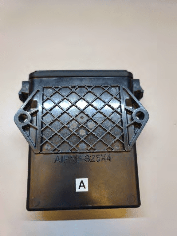
JUP-SMSE013
Apr 16, 2024RFID Read/Writer for Chemical and Fertilizer application system
Equipment Class
DSS - Part 15 Spread Spectrum Transmitter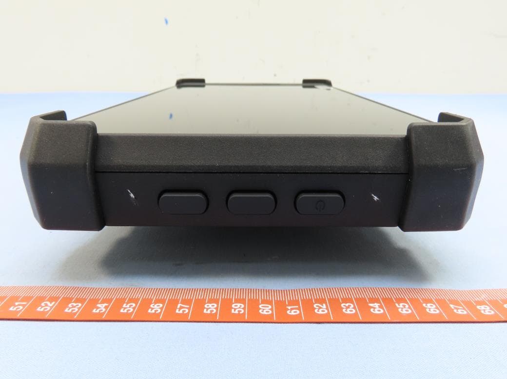
JUP-TD540
Jul 17, 202210 inch Touch Display
Equipment Class
DXX - Part 15 Low Power Communication Device Transmitter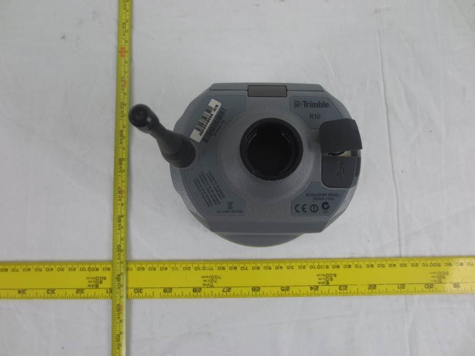
JUP-9091191
Jan 15, 2015GNSS Receiver+900 MHz+Wi-Fi+Bluetooth
Equipment Class
DSS - Part 15 Spread Spectrum Transmitter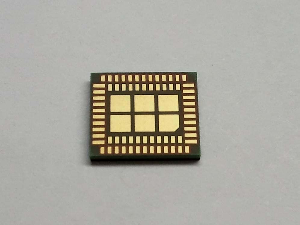
JUP-95807WFBT
Sep 14, 2014WLAN+ Bluetooth Combo Module
Equipment Class
DSS - Part 15 Spread Spectrum Transmitter
JUP88161
Oct 20, 2013GeoExplorer(R) 7 Series handheld, Geo 7X
Equipment Class
DTS - Digital Transmission System