JUPCCKGSM1900
Trimble, Inc.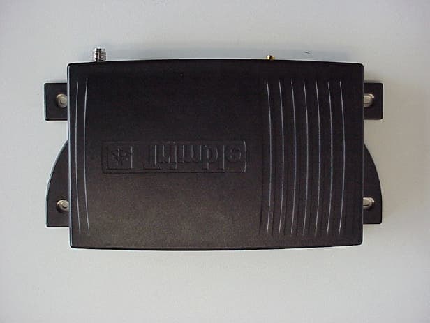
Click to zoom
Application Details
- Equipment Class
- TNB - Licensed Non-Broadcast Station Transmitter
- Date of Grant
- Apr 17, 2001
- Application Purpose
- Original Equipment
- Date of Application
- Feb 22, 2001
- Frequency Range
- 1850.00000000 - 1910.00000000
- Company
- Trimble, Inc.
- Country
- United States
Documents & Files
Document Text
Text extracted from the exhibit documents filed with the FCC. Open a document above to read the original.
Users Manual
CrossCheck GSM 1900 withIQ Event Engine Operation Manual, DRAFT Part Number: 43458-00 Revision: C Date: February, 2001 Trimble Navigation Limited Mobile Positioning and Communications 645 North Mary Avenue Post Office Box 3642 Sunnyvale, CA 94088-3642 U.S.A. +1-800-827-8000 in North America +1-408-481-8000 International FAX: +1-408-481-8214 www.trimble.com Trimble Navigation Limited European Office Trimble Navigation Europe Limited Trimble House Meridian Office Park Osborn Way Hook, Hampshire, RG27 9HX ENGLAND Phone: +44-1256-760-150 FAX: +44-1256-760-148 VoiceMail: +44-1256-761-130 Copyrights © 1997-2001 Trimble Navigation Limited. All rights reserved. No part of this manual may be copied, photocopied, reproduced, translated, or reduced to any electronic medium or machine- readable form without prior written consent from Trimble Navigation Limited. Printed in the United States of America. Printed on recycled paper. Revision Notice This is a pre-release of the CrossCheck GSM Operation Manual, Part Number 43458-00, Revision C, February, 2001, Draft 1. Trademarks Trimble and the Trimble logo are trademarks of Trimble Navigation Limited, registered in the United States and other countries. FleetVision is a registered trademark of Trimble Navigation Limited in the United States. Placer, CrossCheck and IQEvent Engine are trademarks of Trimble Navigation Limited. All other trademarks are property of their respective companies. Disclaimer of Warranty EXCEPT AS OTHERWISE EXPRESSLY PROVIDED IN THE “S OFTWARE A ND F IRMWARE L IMITED W ARRANTY ” AND “H ARDWARE L IMITED W ARRANTY ” SECTIONS BELOW, ALL TRIMBLE HARDWARE, SOFTWARE, FIRMWARE AND DOCUMENTATION IS PROVIDED “AS IS” AND WITHOUT EXPRESS OR IMPLIED WARRANTY OF ANY KIND BY EITHER TRIMBLE NAVIGATION LIMITED OR ANYONE WHO HAS BEEN INVOLVED IN ITS CREATION, PRODUCTION, INSTALLATION, OR DISTRIBUTION, INCLUDING BUT NOT LIMITED TO THE IMPLIED WARRANTIES OF MERCHANTABILITY AND FITNESS FOR A PARTICULAR PURPOSE. THE ENTIRE RISK, AS TO THE QUALITY AND PERFORMANCE OF THE TRIMBLE HARDWARE, SOFTWARE, FIRMWARE AND DOCUMENTATION, IS WITH YOU. SOME STATES DO NOT ALLOW THE EXCLUSION OF IMPLIED WARRANTIES, SO THE ABOVE EXCLUSION MAY NOT APPLY TO YOU. YOU ACKNOWLEDGE AND AGREE THAT TRIMBLE NAVIGATION LIMITED IS NOT RESPONSIBLE FOR THE OPERATION OR FAILURE OF OPERATION OF GPS SATELLITES OR THE AVAILABILITY OF GPS SATELLITE SIGNALS. Limitation of Liability IN NO EVENT WILL TRIMBLE NAVIGATION LIMITED OR ANY PERSON INVOLVED IN THE CREATION, PRODUCTION, INSTALLATION, OR DISTRIBUTION OF THE TRIMBLE HARDWARE, SOFTWARE, FIRMWARE OR DOCUMENTATION BE LIABLE TO YOU OR ANY THIRD PARTY ON ACCOUNT OF ANY CLAIM FOR ANY DAMAGES, INCLUDING ANY LOST PROFITS, LOST SAVINGS, OR OTHER SPECIAL, INCIDENTAL, CONSEQUENTIAL, OR EXEMPLARY DAMAGES, INCLUDING BUT NOT LIMITED TO ANY DAMAGES ASSESSED AGAINST OR PAID BY YOU TO ANY THIRD PARTY, ARISING OUT OF THE USE, INABILITY TO USE, QUALITY OR PERFORMANCE OF SUCH TRIMBLE PRODUCT, EVEN IF TRIMBLE NAVIGATION LIMITED OR ANY SUCH PERSON OR ENTITY HAS BEEN ADVISED OF THE POSSIBILITY OF DAMAGES, OR FOR ANY CLAIM BY ANY OTHER PARTY. SOME STATES DO NOT ALLOW THE LIMITATION OR EXCLUSION OF LIABILITY FOR INCIDENTAL OR CONSEQUENTIAL DAMAGES SO, THE ABOVE LIMITATIONS MAY NOT APPLY TO YOU. Software and Firmware Limited Warranty For a period of ninety (90) days, commencing thirty (30) days after shipment from Trimble, Trimble Navigation Limited warrants that Software and Firmware products will substantially conform to the published specifications provided it is used with the Trimble products, computer products, and operating system for which it was designed. Trimble also warrants for such period that the magnetic media on which Software and Firmware are distributed and the documentation are free from defects in materials and workmanship. Such warranty shall not apply in the event or to the extent that data supplied by you contains errors or is improperly or incorrectly installed. During the ninety (90) day warranty period, Trimble will replace defective media or documentation, or correct substantial program errors at no charge. If Trimble is unable to replace defective media or documentation, or correct program errors, Trimble will refund the price paid for the Software or Firmware. These are your sole remedies for any breach of warranty. Trimble Software and Firmware is provided subject to the further terms and conditions of the relevant End User License Agreement included with such product. Hardware Limited Warranty Trimble Navigation Limited products are warranted against defects in material and workmanship for a period of one year. The warranty period shall commence thirty (30) days after shipment from Trimble’s factory. Warranty service will be provided at a designated Trimble Service Center. Trimble will at its option either repair or replace products that prove to be defective. If Trimble is unable to replace the products, Trimble will refund the price paid for the products. The Customer shall pay all shipping charges for products returned to Trimble for warranty service. Trimble shall pay all shipping charges for the return of products to the Customer. Trimble reserves the right to use either new, or warranted as new, replacement parts to repair the defective product. All used parts shall become the property of Trimble. These are your sole remedies, and Trimble’s sole liability, for any breach of warranty. The above warranty shall not apply to defects resulting from: 1. Improper or inadequate maintenance by the buyer 2. Buyer-supplied software or interfacing 3. Unauthorized modification or misuse 4. Operation outside of the environmental specifications of the product 5. Improper installation, where applicable 6. Lightning or other electrical discharge 7. Fresh or salt water immersion or spray 8. Normal wear and tear on consumable parts (for example, batteries and cables) REGULATORY APPROVALS FCC FCC Part 24, Part 15 Industry Canada This device …
Text truncated - open the document above for the full version.
External Photos
Photographs of the equipment Photograph no.: 1 Photographs of the equipment Photograph no.: 2
ID Label/Location Info
F Below is the proposed FCC ID and text that will be added to the current label product label. The product label is located on the bottom of the CrossCheck GSM 1900 unit. (See bottom unit picture). FCC ID: JUPCCKGSM1900 This device complies with part 15 of the FCC Rules. Operation is subject to the following two conditions: (1) This device may not cause harmful interference, and (2) This device must accept any interference received, including interference that may cause undesired operation 1.3 inches 0.45 inches
Internal Photos
Photographs of the equipment Photograph no.: 4 Photographs of the equipment Photograph no.: 5 Photographs of the equipment Photogtaph no. 6 Photographs of the equipment Photogtaph no. 7
RF Exposure Info
Trimble Navigation 645 North Mary Av., BLD-12, PO Box 3648 Sunnyvale, CA 94088 3642 Federal Communications Commission Authorization and Evaluation Division 7435 Oakland Mills Road Columbia, MD 21046 Attention: Reviewing Engineer The CrossCheck ® GSM radio is a regular GSM product exclusively designed for mainly mobile and some fewer fixed-mount applications (Please refer to CrossCheck GSM 1900 data sheet) for Asset management applications like fleet management etc. Included in the users manual (page 56) are definitions for fixed and mobile applications and limitations of the antenna gain as appropriate for each application to ensure that the end user have been provided with the right information to permit them to avoid exceeding RF exposure guidelines as provided in the Commission’s rule. This information includes the following : A minimum separation distance of 20 cm must be maintained between the antenna and the person for this device to satisfy the RF exposure requirements of the FCC. For fixed mount operation, the antenna co-location requirements of Section 1.1307 (b) (3) of the FCC rules must be satisfied. For fixed mount operation, the maximum gain of the antenna must not exceed 7 dBi. For mobile operation the maximum gain of the antenna must not exceed 3 dBi. WARNING! Use of this unit in portable operations is not permitted. The maximum output power allowed for the GSM 1900 radio is 1W, and the maximum gain of the antennas to be used is 7dBi (for fixed installation). The worst-case EIRP is when the highest gain antenna is used: Maximum EIRP = 30 + 7 = 37 dBm (5 W); equivalent to 61.31V/m in 20 cm distance Regarding MPE limits, GPUC environment limits maximum exposure to 1 mW/cm 2. The power density at 0.2 meters from an antenna is: S = E 2 /3770=-37.7H 2 = 0.997 mW/cm 2 < 1 mW/cm 2 Where: S = Power density (mW/cm 2) E = electrical field strength (V/m) Calculations are based on standard formula for calculating field strength at a distance and converting power density using free space impedance. Further the device uses the GSM protocol which TDD format ratio of 1/8 the 0.997 is further reduced by this ratio or it is equivalent to 0.124 mW/cm 2 . Since compliance is shown for the worst-case condition for the fixed installation, compliance for the mobile application with an antenna gain of maximum of 3 dBi is assured. If you should have any questions regarding this submission, please feel free to contact the undersigned. CrossCheck ® GSM Yours tr ul y, Jorge Herauld Design engineer Trimble Navigation
Test Report
CETECOM CETECOM Inc . 411 Dixon Landing Road, Milpitas, CA-95035, USA Phone: +1 408 586 6200 Fax: +1 408 586 6299 CETECOM ICT Services GmbH Radio Satellite Communication Untertürkheimer Straße 6-10 . D-66117 Saarbrücken Telefon: +49 (0)681 598-9100 Telefax: -9075 I ssued test report consist of 55 PagesPage 1 (55 ) Test report no.: 104/2001/FCC FCC Part 24 FCC ID : JUPCCKGSM1900 Accredited Testing Laboratory DAR-Registration number: TTI-P-G 166/98-00 CETECOM Inc. Test report no. : 104/2001/FCCIssue date: 2001.28.01Page 2 (55) Table of Contents 1 General information 1.1 Notes 1.2 Testing laboratory 1.3 Details of applicant 1.4 Application details 1.5 Test item 1.6 Test standards 2 Technical test 2.1 Summary of test results 2.2 Test report 1 General information 1.1 Notes The test results of this test report relate exclusively to the test item specified in 1.5. The CETECOM Inc. does not assume responsibility for any conclusions and generalisations drawn from the test results with regard to other specimens or samples of the type of the equipment represented by the test item. The test report may only be reproduced or published in full. Reproduction or publication of extracts from the report requires the prior written approval of the CETECOM Inc. 1.2Testing laboratory CETECOM ICT Services GmbH Radio Satellite Communication Untertürkheimer Straße 6-10 . D-66117 Saarbrücken Telefon: +49 (0)681 598-9100 Telefax: +49 (0)681 598-9075 E-mail : [email protected] Internet: www.cetecom.com Accredited testing laboratory DAR-registration number: TTI-P-G 166/98-00 CETECOM Inc. Test report no. : 104/2001/FCCIssue date: 2001.28.01Page 3 (55) 1.3Details of applicant Name : Trimble Navigation Street :645 North Mary Av., BLD-12, PO Box 3648 City : Sunnyvale, CA 94088 3642 Country : USA Telephone : 408 481 2269 Telefax : 408 481 2020 Contact : Jorge Heraud e-mail : [email protected] Telephone : 408 481 8853 1.4Application details Date of receipt of application : 20 Jan. 2001 Date of receipt of test item : 25 Jan. 2001 Date of test : 25-26 Jan. 2001 1.5Test item Type of equipment : GSM/GPS 1900 Mobile Navigation Device Type designation: CrossCheck ® GSM Manufacturer:applicant Street: City: Country: Serial number: Additional informations: : Frequency:1850 - 1910 MHz Type of modulation:GSM-1900 Number of channels : Antenna:0dbi to 3dbi for mobile applications & 0dbi to 7dbi for fixed installations. Power supply:9-32 VDC/2A Output power:29.9dBm Peak / ERP : 23.57dBm (Burst); EIRP: 25.67dBm (Burst) EUT Temp. Tolerance:Temperature range : -20°C - +55°C 1.6Test standards: FCC Part 24 CETECOM Inc. Test report no. : 104/2001/FCCIssue date: 2001.28.01Page 4 (55) 2 Technical test 2.1Summary of test results No deviations from the technical specification(s) were ascertained in the course of the tests performed. Technical responsibility for area of testing: 23.02.0114.02.01 RSCMicheal Berg DateSectionNameSignature Technical responsibility for area of testing : 23.02.0114.02.01EMCLothar Schmidt DateSectionNameSignature CETECOM Inc. Test report no. : 104/2001/FCCIssue date: 2001.28.01Page 5 (55) 2.2Test report TEST REPORT Test report no.: 104/2001/FCC CETECOM Inc. Test report no. : 104/2001/FCCIssue date: 2001.28.01Page 6 (55) TEST REPORT REFERENCE LIST OF MEASUREMENTS PARAMETER TO BE MEASURED ParagraphPAGE POWER OUTPUT SUBCLAUSE § 24.232 7 FREQUENCY STABILITY SUBCLAUSE § 24.235 12 EMISSIONS LIMITS §24.238 14 CONDUCTED SPURIOUS EMISSIONS31 OCCUPIED BANDWIDTH §2.989 38 CONDUCTED EMISSIONS § 15.107/207 45 TEST EQUIPMENT AND ANCILLARIES USED FOR TESTS 46 TEST SITE 47 PHOTOGRAPHS OF THE EQUIPMENT 49 CETECOM Inc. Test report no. : 104/2001/FCCIssue date: 2001.28.01Page 7 (55) POWER OUTPUT SUBCLAUSE § 24.232 Summary: This paragraph contains both average , peak output powers and EIRP measurements for the EUT. In all cases, the peak output power is within the required mask (this mask is specified in the JTC standards, TIA PN3389 Vol. 1 Chap 7, and is no FCC requirement). Method of Measurements: The EUT was set up for the max. output power with pseudo random data modulation. The power was measured with R&S Spectrum Analyzer FSEM 30 ( peak and average) This measurements were done at 3 frequencies, 1850.2 MHz, 1880.0 MHz and 1909.8 MHz (bottom, middle and top of operational frequency range) Limits: Power StepNominal Peak Output Power (dBm) Tolerance (dB) 0+30 ± ±± ± 2 Power Measurements: Conducted: F requency (MHz) Power Step Peak Output P ower (dBm) Average Output P ower (dBm) 1850.2029.7020.37 1880.0029.9120.58 1909.8029.6120.28 Measurement uncertainty ± ±± ± 0.5 dB CETECOM Inc. Test report no. : 104/2001/FCCIssue date: 2001.28.01Page 8 (55) EIRP Measurements Description: This is the test for the maximum radiated power from the EUT. Rule Part 24.232(b) specifies that "Mobile/portable stations are limited to 2 watts e.i.r.p. peak power..." and 24.232(c) specifies that "Peak transmit power must be measured over any interval of continuous transmission using instrumentation calibrated in terms of an rms-equivalent voltage." Method of Measurement: 1. In an anechoic antenna test chamber, a half-wave dipole antenna for the frequency band of interest is placed at the reference center of the chamber. An RF Signal source for the frequency band of interest is connected to the dipole with a cable that has been constructed to not interfere with the radiation pattern of the antenna. A known (measured) power (Pin) is applied to the input of the dipole, and the power received (Pr) at the chamber's probe antenna is recorded. 2. A "reference path loss" is established as Pin + 2.1 - Pr. 3. The EUT is substituted for the dipole at the reference center of the chamber. The EUT is put into CW test mode and a scan is performed to obtain the radiation pattern. 4. From the radiation pattern, the co-ordinates where the maximum antenna gain occurs is identified. 5. The EUT is then put into pulse mode at its maximum power level (Power Step 0). 6. …
Text truncated - open the document above for the full version.
Test Setup Photos
Test site RADIATED EMISSIONS Test site: CONDUCTED EMISSIONS
Contact Information
Applicant
Tony Phan(Engineering Management, GNSS Core R&D)
Technical Contact
TRP/Cetecom bvbaPhillip Inglis
[email protected]410 531 3439
14085 Howard Rd · Dayton, Maryland · United States
Non-Technical Contact
TRP/Cetecom bvbaPhillip Inglis
[email protected]410 531 3439
Technical Specifications
| # | Rule Parts | Frequency Range | Power Output | Emission | Tolerance |
|---|---|---|---|---|---|
| 1 | 24 | 1.85 GHz - 1.91 GHz | 1 W | 330KGXW | 0.1000000000 ppm |
Other Applications from Trimble, Inc.
JUP-SMSE013
Apr 16, 2024RFID Read/Writer for Chemical and Fertilizer application system
Equipment Class
DSS - Part 15 Spread Spectrum Transmitter
JUP-TD540
Jul 17, 202210 inch Touch Display
Equipment Class
DXX - Part 15 Low Power Communication Device Transmitter
JUP-9091191
Jan 15, 2015GNSS Receiver+900 MHz+Wi-Fi+Bluetooth
Equipment Class
DSS - Part 15 Spread Spectrum Transmitter
JUP-95807WFBT
Sep 14, 2014WLAN+ Bluetooth Combo Module
Equipment Class
DSS - Part 15 Spread Spectrum Transmitter
JUP88161
Oct 20, 2013GeoExplorer(R) 7 Series handheld, Geo 7X
Equipment Class
DTS - Digital Transmission System