JUPTRIMTRAC1Trim Trac Locator
Trimble, Inc.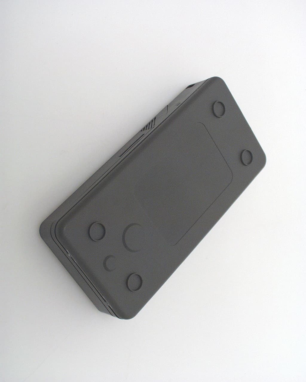
Click to zoom
Application Details
- Equipment Class
- PCB - PCS Licensed Transmitter
- Date of Grant
- Feb 12, 2004
- Application Purpose
- Original Equipment
- Date of Application
- Feb 12, 2004
- Equipment Note
- Trim Trac Locator
- Frequency Range
- 1850.20000000 - 1909.90000000
- Company
- Trimble, Inc.
- Country
- United States
Documents & Files
Document Text
Text extracted from the exhibit documents filed with the FCC. Open a document above to read the original.
Users Manual
TrimTrac Locator Technical Manual ****DRAFT*** Part Number XXXXX-XX-ENG Draft Revision 1.0 January 2004 Corporate Office Trimble Navigation Limited 749 North Mary Avenue Post Office Box 3642 Sunnyvale, CA 94088-3642 U.S.A. Phone: +1-408-481-8940 1-800-545-7762 www.trimble.com Copyright and Trademarks © 1997–2004, Trimble Navigation Limited. All rights reserved. Printed in the United States of America. Printed on recycled paper. The Circle & Parallelogram and TrimTrac are trademarks of Trimble Navigation Limited. The Sextant logo, Globe & Triangle and Trimble are trademarks of Trimble Navigation Limited, registered in the United States Patent and Trademark Office. All other trademarks are the property of their respective owners. Release Notice This is January 2004 release (Revision A) of the TrimTrac TM Locator Technical Manual, Part Number XXXX-YY-ENG. The following limited warranties give you specific legal rights. You may have others, which vary from state/jurisdiction to state/jurisdiction. Hardware Limited Warranty Trimble warrants that this Trimble hardware product (the “Product”) shall be free from defects in materials and workmanship and will substantially conform to Trimble’s applicable published specifications for the Product for a period of one (1) year, starting from the date of delivery. The warranty set forth in this paragraph shall not apply to software/firmware products. Software and Firmware License, Limited Warranty This Trimble software and/or firmware product (the “Software”) is licensed and not sold. Its use is governed by the provisions of the applicable End User License Agreement (“EULA”), if any, included with the Software. In the absence of a separate EULA included with the Software providing different limited warranty terms, exclusions, and limitations, the following terms and conditions shall apply. Trimble warrants that this Trimble Software product will substantially conform to Trimble’s applicable published specifications for the Software for a period of ninety (90) days, starting from the date of delivery. Warranty Remedies Trimble's sole liability and your exclusive remedy under the warranties set forth above shall be, at Trimble’s option, to repair or replace any Product or Software that fails to conform to such warranty (“Nonconforming Product”), or refund the purchase price paid by you for any such Nonconforming Product, upon your return of any Nonconforming Product to Trimble in accordance with Trimble’s standard return material authorization procedures. Warranty Exclusions and Disclaimer These warranties shall be applied only in the event and to the extent that: (i) the Products and Software are properly and correctly installed, configured, interfaced, maintained, stored, and operated in accordance with Trimble's relevant operator's manual and specifications, and; (ii) the Products and Software are not modified or misused. The preceding warranties shall not apply to, and Trimble shall not be responsible for defects or performance problems resulting from (i) the combination or utilization of the Product or Software with products, information, data, systems or devices not made, supplied or specified by Trimble; (ii) the operation of the Product or Software under any specification other than, or in addition to, Trimble's standard specifications for its products; (iii) the unauthorized modification or use of the Product or Software; (iv) damage caused by accident, lightning or other electrical discharge, fresh or salt water immersion or spray; or (v) normal wear and tear on consumable parts (e.g., batteries). THE WARRANTIES ABOVE STATE TRIMBLE'S ENTIRE LIABILITY, AND YOUR EXCLUSIVE REMEDIES, RELATING TO PERFORMANCE OF THE PRODUCTS AND SOFTWARE. EXCEPT AS OTHERWISE EXPRESSLY PROVIDED HEREIN, THE PRODUCTS, SOFTWARE, AND ACCOMPANYING DOCUMENTATION AND MATERIALS ARE PROVIDED “AS-IS” AND WITHOUT EXPRESS OR IMPLIED WARRANTY OF ANY KIND BY EITHER TRIMBLE NAVIGATION LIMITED OR ANYONE WHO HAS BEEN INVOLVED IN ITS CREATION, PRODUCTION, INSTALLATION, OR DISTRIBUTION INCLUDING, BUT NOT LIMITED TO, THE IMPLIED WARRANTIES OF MERCHANTABILITY AND FITNESS FOR A PARTICULAR PURPOSE, TITLE, AND NONINFRINGEMENT. THE STATED EXPRESS WARRANTIES ARE IN LIEU OF ALL OBLIGATIONS OR LIABILITIES ON THE PART OF TRIMBLE ARISING OUT OF, OR IN CONNECTION WITH, ANY PRODUCTS OR SOFTWARE. SOME STATES AND JURISDICTIONS DO NOT ALLOW LIMITATIONS ON DURATION OR THE EXCLUSION OF AN IMPLIED WARRANTY, SO THE ABOVE LIMITATION MAY NOT APPLY TO YOU. TRIMBLE NAVIGATION LIMITED IS NOT RESPONSIBLE FOR THE OPERATION OR FAILURE OF OPERATION OF GPS SATELLITES OR THE AVAILABILITY OF GPS SATELLITE SIGNALS. Limitation of Liability TRIMBLE’S ENTIRE LIABILITY UNDER ANY PROVISION HEREIN SHALL BE LIMITED TO THE GREATER OF THE AMOUNT PAID BY YOU FOR THE PRODUCT OR SOFTWARE LICENSE OR U.S.$25.00. TO THE MAXIMUM EXTENT PERMITTED BY APPLICABLE LAW, IN NO EVENT SHALL TRIMBLE OR ITS SUPPLIERS BE LIABLE FOR ANY INDIRECT, SPECIAL, INCIDENTAL OR CONSEQUENTIAL DAMAGES WHATSOEVER UNDER ANY CIRCUMSTANCE OR LEGAL THEORY RELATING IN ANY WAY TO THE PRODUCTS, SOFTWARE AND ACCOMPANYING DOCUMENTATION AND MATERIALS, (INCLUDING, WITHOUT LIMITATION, DAMAGES FOR LOSS OF BUSINESS PROFITS, BUSINESS INTERRUPTION, LOSS OF BUSINESS INFORMATION, OR ANY OTHER PECUNIARY LOSS), REGARDLESS WHETHER TRIMBLE HAS BEEN ADVISED OF THE POSSIBILITY OF ANY SUCH LOSS AND REGARDLESS OF THE COURSE OF DEALING WHICH DEVELOPS OR HAS DEVELOPED BETWEEN YOU AND TRIMBLE. BECAUSE SOME STATES AND JURISDICTIONS DO NOT ALLOW THE EXCLUSION OR LIMITATION OF LIABILITY FOR CONSEQUENTIAL OR INCIDENTAL DAMAGES, THE ABOVE LIMITATION MAY NOT APPLY TO YOU. Notices Class B Statement – Notice to Users. This equipment has been tested and found to comply with the limits for a Class B digital device, pursuant to Part 15 of the FCC rules. These limits are designed to provide reasonable protection against harmful interference in a residential installation. This equipment generates, us…
Text truncated - open the document above for the full version.
ID Label/Location Info
PROPOSED FCC ID LABEL AND LOCATION TRIMBLE NAVIGATION LIMITED This device complies with Part 24 of the FCC Rules. FCC ID: JUPTRIMTRAC1 FCC ID LABEL LOCATION
Parts List/Tune Up Info
TRIMBLE rev.2 May 7, 2003 CONFIDENTIAL CH1RFL 1 U FS START800.000000MHzSTOP2100.000000MHz TRIMBLE REV.2 Cor CH2RFL SWR1 /REF 1 Cor 7 May 2003 16:07:17 1 2 3 4 5 5:27.3145.9414552.98pH1710.000000MHz CH1Markers 1:14.236 -6.5317 824.000MHz 2:33.518 -40.273 960.000MHz 3:73.473 22.648 1.85000GHz 4:44.367 -33.951 1.99000GHz 1 2 3 4 5 5:1.86691710.000000MHz CH2Markers 1:3.5895 824.000MHz 2:2.7721 960.000MHz 3:1.7030 1.85000GHz 4:2.0452 1.99000GHz CONFIDENTIAL CONFIDENTIAL +90 180 -90 0 CONFIDENTIAL +90 180 -90 0 CONFIDENTIAL Elevation 1 total gain CONFIDENTIAL 0 +90 180 -90 CONFIDENTIAL 0 +90 180 -90 CONFIDENTIAL Elevation 2 total gain CONFIDENTIAL 0 -90 +90 CONFIDENTIAL 0 -90 +90 CONFIDENTIAL Azimuth total gain CH1RFL 1 U FS START1567.900000MHzSTOP1582.900000MHz TRIMBLE REV.2 C CH2RFL SWR1 /REF 1 C 7 May 2003 16:09:54 1 2 3 2:35.838-2.904334.785pF1575.372000MHz CH1Markers 1:34.789 -22.598 1.56790GHz 3:37.246 17.518 1.58290GHz 1 2 3 2:1.40471575.372000MHz CH2Markers 1:1.9004 1.56790GHz 3:1.6437 1.58290GHz CONFIDENTIAL CONFIDENTIAL +90 180 -90 0 CONFIDENTIAL +90 180 -90 0 CONFIDENTIAL Elevation 1 total gain CONFIDENTIAL 0 +90 180 -90 CONFIDENTIAL 0 +90 180 -90 CONFIDENTIAL Elevation 2 total gain CONFIDENTIAL 0 -90 +90 CONFIDENTIAL 0 -90 +90 CONFIDENTIAL Azimuth total gain
Parts List/Tune Up Info
Trimble Navigation Proprietary TRIMTRAC CALIBRATION PROCEDURES Trimble Navigation Proprietary 1INTRODUCTION1 1.1Overview1 1.2Measurable Parameters1 1.3Calibration and Development Signals2 1.4Equipment Required2 1.5Terminology2 2PRE-CALIBRATION4 3AUTOMATIC FREQUENCY CORRECTION5 3.1Purpose5 3.2Theory5 3.3Example6 4AUTOMATIC GAIN CONTROL8 4.1Purpose8 4.2Theory8 4.3Example8 5RSSI CORRECTION10 5.1Purpose10 5.2Theory10 5.3Example11 6TRANSMIT POWER SCALING FACTORS12 6.1Purpose12 6.2Theory12 6.3Example13 7TRANSMIT POWER FREQUENCY COMPENSATION14 7.1Purpose14 7.2Theory14 8POST CALIBRATION17 8.1Leaving Test Mode17 8.2Storing Calibration Data17 Trimble Navigation Proprietary 1 INTRODUCTION 1.1 Overview This document describes a suggested calibration procedure for all of the measurable parameters of the target platform in production. Individual sections cover each procedure. Information on how the resultant calibration data may be incorporated into the target platform is included in the relevant configuration manual for the platform. 1.2 Measurable Parameters The aim of the calibration procedure is to measure the following parameters: TypeNameSee Section Size SignedInt32 slopePPB 3 Int16 nominalAfcValue 3 Int16 gainControlCodeTable 4 RADIO_GAIN_TABLE_SIZE SignedInt16 accurateRadioGainTable 4 RADIO_GAIN_TABLE_SIZE SignedInt8 rssiCorrectionTable 5BAND_SIZE (number of channels in the band) Int16 rampFactorTable 6 NUM_POWER_CONTROL_LEVELS Int16 txFreqCompensation 7BAND_SIZE/4 Note: the gainControlCodeTable, accurateRadioGainTable, rssiCorrectionTable, rampFactorTable and txFreqCompensation contain “size” values for each of the supported bands. – 2 – Trimble Navigation Proprietary 1.3 Calibration and Development Signals The procedures describe use the following Calibration and Development (CalDev) signals: • CalDevGsmReq & CalDevGsmCnf • CalDevGsmFinishReq & CalDevGsmFinishCnf • CalDevGsmRssiReq & CalDevGsmRssiCnf • CalDevGsmFreqOffsetMeasReq & CalDevGsmFreqOffsetMeasCnf • CalDevGsmSetPowerRampReq & CalDevGsmSetPowerRampCnf • CalDevGsmDcOffsetReq & CalDevGsmDcOffsetCnf • CalDevGsmGainProgramReq & CalDevGsmGainProgramCnf • CalDevGsmBurstReq & CalDevGsmBurstCnf • CalDevGsmSetAfcDacReq & CalDevGsmSetAfcDacCnf • CalDevGsmSetBurstDataReq & CalDevGsmSetBurstDataCnf • CalDevGsmRxControlReq & CalDevGsmRxControlCnf • CalDevGsmRampScaleReq & CalDevGsmRampScaleCnf • CalDevGsmSetBandModeReq 1.4 Equipment Required The suggested equipment required is a PC with a GPIB card to control a Signal Generator and a Power Meter, or appropriate GSM tester. The target will be controlled via the serial interface. Figure 1 Typical calibration station 1.5 Terminology The following abbreviations are used throughout this document: GPIB PC Signal Generator / Power Meter Target RS232 RF Cable – 3 – Trimble Navigation Proprietary AFCAutomatic Frequency Correction AGCAutomatic Gain Control ARFCNAbsolute Radio Frequency Channel Number BBCBase Band Codec DACDigital to Analogue Converter GKIGeneric Kernel Interface GPIBGeneral Purpose Interface Bus NVRAMNon Volatile Random Access Memory RSSIReceived Signal Strength Indication – 4 – Trimble Navigation Proprietary 2 PRE-CALIBRATION Calibration may only be performed whilst the Layer 1 software running on the target platform is in the TEST state, which may only be reached from the NULL state. NULL state is a state where the application layer, protocol stack and layer 1 have been shutdown. How this state is reached is dependent on the software build and hardware implementation, but it should be possible to enter NULL state by sending a signal to the target from the PC using Genie. If a full Application Layer build is running, an ApexEmEnterNullStateSig needs to be sent to the Application Foreground Layer task. This will shutdown the Application Layer and Protocol Stack and causes an MphDeactivateReq signal to be sent, shutting down Layer 1. If a PS application build is being used then an MphDeactivateReq signal may be sent directly to the Layer 1 Background task from Genie. Figure 2 Excerpt of Layer 1 State Diagram Prior to starting calibration, assuming that the platform is connected as illustrated in Figure 1 and in the NULL state, there are two steps to perform: • notify the target to process received signals • place the target into the TEST state NULL STATE TEST STATE ANY STATE MphDeactivateReq CalDevGsmReq CalDevGsmFinishReq – 5 – Trimble Navigation Proprietary 3 AUTOMATIC FREQUENCY CORRECTION 3.1 Purpose Calibration of the AFC is carried out to ensure that the target’s clock frequency can correctly synchronise to that of the network. 3.2 Theory Because the relationship between the DAC and the clock frequency is an essentially linear one, the AFC calibration of an individual target may be characterised by two parameters: • a nominal value • the gradient of the VCXO The nominal value is the DAC value required to give a zero frequency offset between the target and the signal generator tuned to the centre frequency of the mid-band channel. The gradient allows for the calculation of the correct DAC value for all other frequency offsets. The calibration procedure outlined assumes that a theoretical nominal value has been calculated for the radio used. Figure 3 AFC Calibration fbMax fbMin 0 Multi plier Divisor Frequency offset DAC dacMin dacMax theoretical nominal value nominal value -500 +500 – 6 – Trimble Navigation Proprietary 3.3 Example Below is a description of how to calculate the AFC slope (slopePPB) and nominal value ( nominalAfcValue) using CalDevGsmFreqOffsetMeasReq and CalDevGsmFreqOffsetMeasCnf signals. These signals measure frequency bursts to detect the frequency offset. frequency = MID_CHANNEL_FREQUENCY + 0.0677083333 MHz /* see note 1 */ amplitude = -62dBm + CABLE_LOSS SET Signal Generator TO frequency & amplitude WITH MODULATION_OFF SEND CalDevGsmFreqOffsetMeasReq (MID_CHANNEL_ARFCN, dacMax) WAIT FOR CalDevGsmFreqOffsetMeasCnf (freqBurstFound, frequencyOffset) IF freqBurstFound =…
Text truncated - open the document above for the full version.
RF Exposure Info
in accordance with the requirements of FCC Report and Order: ET Docket 93-62, and OET Bulletin 65 Supplement C for TrimTrac Model: 51200-10 FCC ID: JUPTRIMTRAC1 January 7, 2004 REPORT NO: 03U2250-2A Prepared for Trimble Navigation Limited 749 North Mary Ave Sunnyvale, CA 94086, USA Prepared by COMPLIANCE CERTIFICATION SERVICES 561F MONTEREY ROAD MORGAN HILL, CA 95037 USA TEL: (408) 463-0885 REPORT NO: 03U2250-2A DATE: January 7, 2004 FCC ID: JUPTRIMTRAC1 COMPLIANCE CERTIFICATION SERVICES Page: 2 of 30 This report shall not be reproduced except in full, without the written approval of CCS. This document may be altered or revised by Compliance Certification Services personnel only, and shall be noted in the revision section of the document. CERTIFICATE OF COMPLIANCE (SAR EVALUATION) Dates of Tests: January 7, 2004 APPLICANT: Trimble Navigation Limited 749 North Mary Ave Sunnyvale, CA 94086, USA MODEL NAME: 51200-10 FCC ID: JUPTRIMTRAC1 DEVICE CATEGORY: PORTABLE DEVICES EXPOSURE CATEGORY: GENERAL POPULATION/UNCONTROLLED EXPOSURE Test Sample is a: Production unit Tx Frequency: 1850.2 to 1909.8 MHz Max. O/P Power: (Conducted/Peak) 30.71 dBm Max. SAR (1g): 0.669 mW/g Application Type: Certification FCC Rule Part(s): 24 E Note: This device contains GSM900 and GSM1800 function not operational in US territories. This report is only applicable for GSM1900 PCS band. This wireless portable device has been shown to be capable of compliance for localized specific absorption rate (SAR) for uncontrolled environment/general population exposure limits specified in ANSI/IEEE Std. C95.1-1992 and had been tested in accordance with the measurement procedures specified in FCC OET 65 Supplement C (released on 6/29/2001 see Test Report). I attest to the accuracy of data. All measurements reported herein were performed by me or were made under my supervision and are correct to the best of my knowledge and belief. I assume full responsibility for the completeness of these measurements and vouch for the qualifications of all persons taking them. Steve Cheng EMC Engineering Manager REPORT NO: 03U2250-2A DATE: January 7, 2004 FCC ID: JUPTRIMTRAC1 COMPLIANCE CERTIFICATION SERVICES Page: 3 of 30 This report shall not be reproduced except in full, without the written approval of CCS. This document may be altered or revised by Compliance Certification Services personnel only, and shall be noted in the revision section of the document. TABLE OF CONTENTS 1. EQUIPMENT UNDER TEST (EUT) DESCRIPTION..................................................................4 2. REQUIREMENTS FOR COMPLIANCE TESTING DEFINED BY THE FCC...................................4 3. DOSIMETRIC ASSESSMENT SYSTEM...................................................................................4 3.1. MEASUREMENT SYSTEM DIAGRAM..................................................................................................................5 3.2. SYSTEM COMPONENTS.....................................................................................................................................6 4. EVALUATION PROCEDURES...............................................................................................8 5. MEASUREMENT UNCERTAINTY.........................................................................................12 6. EXPOSURE LIMIT..............................................................................................................13 7. MEASUREMENT RESULTS................................................................................................14 7.1. TEST LIQUID CONFIRMATION...........................................................................................................................14 7.2. SYSTEM PERFORMANCE CHECK....................................................................................................................16 7.3. EUT TUNE-UP PROCEDURES.........................................................................................................................18 7.4. SAR MEASUREMENTS RESULTS....................................................................................................................19 8. EUT PHOTO....................................................................................................................24 9. EQUIPMENT LIST & CALIBRATION STATUS.......................................................................28 10. REFERENCES...................................................................................................................29 11. ATTACHMENTS.................................................................................................................30 REPORT NO: 03U2250-2A DATE: January 7, 2004 FCC ID: JUPTRIMTRAC1 COMPLIANCE CERTIFICATION SERVICES Page: 4 of 30 This report shall not be reproduced except in full, without the written approval of CCS. This document may be altered or revised by Compliance Certification Services personnel only, and shall be noted in the revision section of the document. 1. EQUIPMENT UNDER TEST (EUT) DESCRIPTION The EUT is a Tri-band GSM cellular transceiver with a GPS receiver built-in. The device is a stand- alone unit design to be placed in a high-value asset such as a vehicle or cargo-container. The device has built in Tri-Band GSM900, DCS1800, and PCS1900 cellular antenna embedded in the only PCB used in the product. TX Frequency: GSM1900 - 1850.2 MHz to 1909.9 MHz GSM1800 - 1710.2 MHz to 1784.8 MHz GSM900 - 880.2 MHz to 914.8 MHz Duty Cycle: 12.5% Battery: AA Alkaline type 2. REQUIREMENTS FOR COMPLIANCE TESTING DEFINED BY THE FCC The US Federal Communications Commission has released the report and order “Guidelines for Evaluating the Environmental Effects of RF Radiation", ET Docket No. 93-62 in August 1996 [1]. The order requires routine SAR evaluation prior to equipment authorization of portable transmitter devices, including portable telephones. For consumer products, the applicable limit is 1.6 mW/g, for…
Text truncated - open the document above for the full version.
RF Exposure Info
Date/Time: 01/07/04 09:38:12 Test Laboratory: Compliance Certification Services D1800V2 SN294_010704 DUT: Dipole 1800 MHz; Type: D1800V2; Serial: 294 Program Name: System Performance Check at 1800 MHz Ambient Temperature: 22.5 deg C; Liquid Temperature: 21.0 deg C Communication System: CW; Frequency: 1800 MHz;Duty Cycle: 1:1 Medium: Head 1800 MHz (σ = 1.467 mho/m, ε r = 40.069, ρ = 1000 kg/m 3 ) Phantom section: Flat Section DASY4 Configuration: z Probe: ES3DV2 - SN3021; ConvF(5.1, 5.1, 5.1); Calibrated: 7/29/2003 z Sensor-Surface: 4mm (Mechanical Surface Detection) z Electronics: DAE3 Sn427; Calibrated: 2/4/2003 z Phantom: SAM 2; Type: SAM 2; Serial: 1050 z Measurement SW: DASY4, V4.1 Build 47; Postprocessing SW: SEMCAD, V1.8 Build 62 d=10mm; Pin=250mW/Area Scan (7x7x1): Measurement grid: dx=15mm, dy=15mm Reference Value = 89 V/m Power Drift = -0.0 dB Maximum value of SAR = 11 mW/g d=10mm; Pin=250mW/Zoom Scan (5x5x7)/Cube 0: Measurement grid: dx=7.5mm, dy=7.5mm, dz=5mm Peak SAR (extrapolated) = 17.6 W/kg SAR(1 g) = 9.72 mW/g; SAR(10 g) = 5.07 mW/g Reference Value = 89 V/m Power Drift = -0.0 dB Maximum value of SAR = 11 mW/g 0 dB = 11mW/g Date/Time: 01/07/04 09:38:12 Test Laboratory: Compliance Certification Services D1800V2 SN294_010704 DUT: Dipole 1800 MHz; Type: D1800V2; Serial: 294 DASY4 Configuration: z Probe: ES3DV2 - SN3021; ConvF(5.1, 5.1, 5.1); Calibrated: 7/29/2003 z Sensor-Surface: 0mm (Fix Surface) z Electronics: DAE3 Sn427; Calibrated: 2/4/2003 z Phantom: SAM 2; Type: SAM 2; Serial: 1050 z Measurement SW: DASY4, V4.1 Build 47; Postprocessing SW: SEMCAD, V1.8 Build 62 d=10mm; Pin=250mW/Z Scan (1x1x51): Measurement grid: dx=20mm, dy=20mm, dz=2mm Reference Value = 89 V/m Power Drift = -0.0 dB Maximum value of SAR = 12.4 mW/g
RF Exposure Info
Date/Time: 01/07/04 12:57:04 Test Laboratory: Compliance Certification Services Body_C1 DUT: Trimble; Type: 51200-10; Serial: N/A Program Name: Body_C1 Ambient Temperature: 22.5 deg C; Liquid Temperature: 21.0 deg C Communication System: GSM1900; Frequency: 1880 MHz;Duty Cycle: 1:8 Medium: Muscle 1900 MHz (σ = 1.5929 mho/m, ε r = 52.7006, ρ = 1000 kg/m 3 ) Phantom section: Flat Section DASY4 Configuration: z Probe: ES3DV2 - SN3021; ConvF(4.8, 4.8, 4.8); Calibrated: 7/29/2003 z Sensor-Surface: 4mm (Mechanical Surface Detection) z Electronics: DAE3 Sn427; Calibrated: 2/4/2003 z Phantom: SAM 1; Type: SAM 1; Serial: 1185 z Measurement SW: DASY4, V4.1 Build 47; Postprocessing SW: SEMCAD, V1.8 Build 62 d=1.5 cm Body, Low/Area Scan (7x12x1): Measurement grid: dx=15mm, dy=15mm d=1.5 cm Body, Low/Zoom Scan (5x5x7)/Cube 0: Measurement grid: dx=7.5mm, dy=7.5mm, dz=5mm Peak SAR (extrapolated) = 0.178 W/kg SAR(1 g) = 0.117 mW/g; SAR(10 g) = 0.073 mW/g Reference Value = 5.28 V/m Power Drift = 0.1 dB Maximum value of SAR = 0.127 mW/g d=1.5 cm Body, Low/Zoom Scan (5x5x7)/Cube 1: Measurement grid: dx=7.5mm, dy=7.5mm, dz=5mm Peak SAR (extrapolated) = 0.119 W/kg SAR(1 g) = 0.078 mW/g; SAR(10 g) = 0.050 mW/g Reference Value = 5.28 V/m Power Drift = 0.1 dB Maximum value of SAR = 0.085 mW/g Date/Time: 01/07/04 12:57:04 Test Laboratory: Compliance Certification Services Body_C1 DUT: Trimble; Type: 51200-10; Serial: N/A DASY4 Configuration: z Probe: ES3DV2 - SN3021; ConvF(4.8, 4.8, 4.8); Calibrated: 7/29/2003 z Sensor-Surface: 0mm (Fix Surface) z Electronics: DAE3 Sn427; Calibrated: 2/4/2003 z Phantom: SAM 1; Type: SAM 1; Serial: 1185 z Measurement SW: DASY4, V4.1 Build 47; Postprocessing SW: SEMCAD, V1.8 Build 62 d=1.5 cm Body, Low/Z Scan (1x1x41): Measurement grid: dx=20mm, dy=20mm, dz=2.5mm Reference Value = 5.28 V/m Power Drift = 0.0 dB Maximum value of SAR = 0.151 mW/g Date/Time: 01/07/04 11:23:24 Test Laboratory: Compliance Certification Services Body_C2 DUT: Trimble; Type: 51200-10; Serial: N/A Program Name: Body_C2 Ambient Temperature: 22.5 deg C; Liquid Temperature: 21.0 deg C Communication System: GSM1900; Frequency: 1850.2 MHz;Duty Cycle: 1:8 Medium: Muscle 1900 MHz (σ = 1.5929 mho/m, ε r = 52.7006, ρ = 1000 kg/m 3 ) Phantom section: Flat Section DASY4 Configuration: z Probe: ES3DV2 - SN3021; ConvF(4.8, 4.8, 4.8); Calibrated: 7/29/2003 z Sensor-Surface: 4mm (Mechanical Surface Detection) z Electronics: DAE3 Sn427; Calibrated: 2/4/2003 z Phantom: SAM 1; Type: SAM 1; Serial: 1185 z Measurement SW: DASY4, V4.1 Build 47; Postprocessing SW: SEMCAD, V1.8 Build 62 d=1.5 cm Body, Low/Area Scan (7x12x1): Measurement grid: dx=15mm, dy=15mm Reference Value = 6.08 V/m Power Drift = -0.1 dB Maximum value of SAR = 0.428 mW/g d=1.5 cm Body, Low/Zoom Scan (5x5x7)/Cube 0: Measurement grid: dx=7.5mm, dy=7.5mm, dz=5mm Peak SAR (extrapolated) = 0.641 W/kg SAR(1 g) = 0.411 mW/g; SAR(10 g) = 0.239 mW/g Reference Value = 6.08 V/m Power Drift = -0.1 dB Maximum value of SAR = 0.460 mW/g Date/Time: 01/07/04 12:01:40 Test Laboratory: Compliance Certification Services Body_C2 DUT: Trimble; Type: 51200-10; Serial: N/A Program Name: Body_C2 Ambient Temperature: 22.5 deg C; Liquid Temperature: 21.0 deg C Communication System: GSM1900; Frequency: 1880 MHz;Duty Cycle: 1:8 Medium: Muscle 1900 MHz (σ = 1.5929 mho/m, ε r = 52.7006, ρ = 1000 kg/m 3 ) Phantom section: Flat Section DASY4 Configuration: z Probe: ES3DV2 - SN3021; ConvF(4.8, 4.8, 4.8); Calibrated: 7/29/2003 z Sensor-Surface: 4mm (Mechanical Surface Detection) z Electronics: DAE3 Sn427; Calibrated: 2/4/2003 z Phantom: SAM 1; Type: SAM 1; Serial: 1185 z Measurement SW: DASY4, V4.1 Build 47; Postprocessing SW: SEMCAD, V1.8 Build 62 d=1.5 cm Body, Middle/Area Scan (7x10x1): Measurement grid: dx=15mm, dy=15mm Reference Value = 6.62 V/m Power Drift = 0.1 dB Maximum value of SAR = 0.449 mW/g d=1.5 cm Body, Middle/Zoom Scan (5x5x7)/Cube 0: Measurement grid: dx=7.5mm, dy=7.5mm, dz=5mm Peak SAR (extrapolated) = 0.781 W/kg SAR(1 g) = 0.494 mW/g; SAR(10 g) = 0.282 mW/g Reference Value = 6.62 V/m Power Drift = 0.1 dB Maximum value of SAR = 0.542 mW/g Date/Time: 01/07/04 12:19:50 Test Laboratory: Compliance Certification Services Body_C2 DUT: Trimble; Type: 51200-10; Serial: N/A Program Name: Body_C2 Ambient Temperature: 22.5 deg C; Liquid Temperature: 21.0 deg C Communication System: GSM1900; Frequency: 1909.8 MHz;Duty Cycle: 1:8 Medium: Muscle 1900 MHz (σ = 1.5929 mho/m, ε r = 52.7006, ρ = 1000 kg/m 3 ) Phantom section: Flat Section DASY4 Configuration: z Probe: ES3DV2 - SN3021; ConvF(4.8, 4.8, 4.8); Calibrated: 7/29/2003 z Sensor-Surface: 4mm (Mechanical Surface Detection) z Electronics: DAE3 Sn427; Calibrated: 2/4/2003 z Phantom: SAM 1; Type: SAM 1; Serial: 1185 z Measurement SW: DASY4, V4.1 Build 47; Postprocessing SW: SEMCAD, V1.8 Build 62 d=1.5 cm Body, High/Area Scan (7x10x1): Measurement grid: dx=15mm, dy=15mm Reference Value = 6.52 V/m Power Drift = 0.12 dB Maximum value of SAR = 0.465 mW/g d=1.5 cm Body, High/Zoom Scan (5x5x7)/Cube 0: Measurement grid: dx=7.5mm, dy=7.5mm, dz=5mm Peak SAR (extrapolated) = 0.821 W/kg SAR(1 g) = 0.510 mW/g; SAR(10 g) = 0.287 mW/g Reference Value = 6.52 V/m Power Drift = 0.12 dB Maximum value of SAR = 0.561 mW/g Date/Time: 01/07/04 12:19:50 Test Laboratory: Compliance Certification Services Body_C2 DUT: Trimble; Type: 51200-10; Serial: N/A DASY4 Configuration: z Probe: ES3DV2 - SN3021; ConvF(4.8, 4.8, 4.8); Calibrated: 7/29/2003 z Sensor-Surface: 0mm (Fix Surface) z Electronics: DAE3 Sn427; Calibrated: 2/4/2003 z Phantom: SAM 1; Type: SAM 1; Serial: 1185 z Measurement SW: DASY4, V4.1 Build 47; Postprocessing SW: SEMCAD, V1.8 Build 62 d=1.5 cm Body, High/Z Scan (1x1x41): Measurement grid: dx=20mm, dy=20mm, dz=2.5mm Reference Value = 6.52 V/m Power Drift = 0.12 dB Maximum value of SAR = 0.672 mW/g Date/Time: 01/07/04 10:34:48 Test Laboratory: Compliance Certification Services Body_C3 DUT: Trimble; Type: 51200-10; Serial: N/A Program Name: Body_C3 Amb…
Text truncated - open the document above for the full version.
Test Report
FCC CFR47 CERTIFICATION PART 24E TEST REPORT FOR TRIM TRAC MODEL: 51200-00 FCC ID: JUPTRIMTRAC1 REPORT NUMBER: 03U2250-1 ISSUE DATE: JANUARY 6, 2004 Prepared for Trimble Navigation Limited 749 NORTH MARY AVE. SUNNYVAL, CA 94088-3642, USA Prepared by COMPLIANCE CERTIFICATION SERVICES 561F MONTEREY ROAD, ROUTE 2 MORGAN HILL, CA 95037, USA TEL: (408) 463-0885 FAX: (408) 463-0888 REPORT NO: 03U2250-1 DATE: JANUARY 6, 2004 EUT: Trim Trac FCC ID: JUPTRIMTRAC1 Page 2 of 36 COMPLIANCE CERTIFICATION SERVICES DOCUMENT NO: CCSUP4031A 561F MONTEREY ROAD, MORGAN HILL, CA 95037 USA TEL: (408) 463-0885 FAX: (408) 463-0888 This report shall not be reproduced except in full, without the written approval of CCS. This document may be altered or revised by Compliance Certification Services personnel only, and shall be noted in the revision section of the document. TABLE OF CONTENT 1. TEST RESULT CERTIFICATION..........................................................................................3 2. EUT DESCRIPTION................................................................................................................4 3. TEST METHODOLOGY.........................................................................................................4 4. TEST FACILITY......................................................................................................................4 5. ACCREDITATION AND LISTING.........................................................................................4 6. MEASURING INSTRUMENT CALIBRATION......................................................................4 7. TEST SETUP, PROCEDURE AND RESULT..........................................................................5 7.1. SECTION 2.1046: RF POWER OUTPUT.............................................................................5 7.2. SECTION 2.1047: MODULATION CHARACTERISTICS.................................................13 7.3. SECTION 2.1049: OCCUPIED BANDWIDTH..................................................................13 7.4. SECTION 2.1051: SPURIOUS EMISSION AT ANTENNA TERMINAL............................17 7.5. SECTION 2.1053: FIELD STRENGTH OF SPURIOUS RADIATION................................23 7.6. RADIATED EMISSION - DIGITAL TEST........................................................................29 7.7. POWERLINE CONDUCTED EMISSION..........................................................................32 7.8. SECTION 2.1055: FREQUENCY STABILITY..................................................................32 8. APPENDICES.........................................................................................................................36 8.1. EXTERNAL & INTERNAL PHOTOS.....................................................................…
Text truncated - open the document above for the full version.
Contact Information
Applicant
Tony Phan(Engineering Management, GNSS Core R&D)
Test Firm
Compliance Certification Services IncSteve Cheng
Technical Specifications
| # | Rule Parts | Frequency Range | Power Output | Emission | Tolerance |
|---|---|---|---|---|---|
| 1 | 24E | 1.85 GHz - 1.91 GHz | 1.07 W | 266KGXW | 0.4330000000 ppm |
Other Applications from Trimble, Inc.
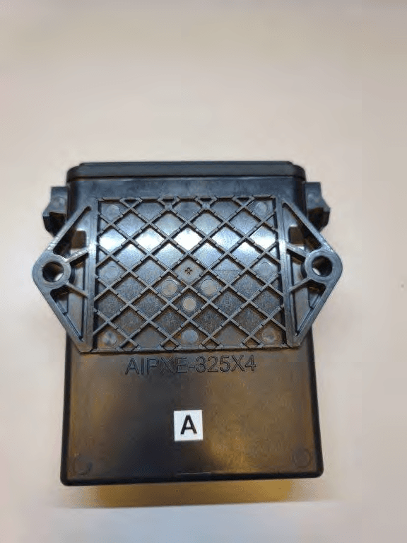
JUP-SMSE013
Apr 16, 2024RFID Read/Writer for Chemical and Fertilizer application system
Equipment Class
DSS - Part 15 Spread Spectrum Transmitter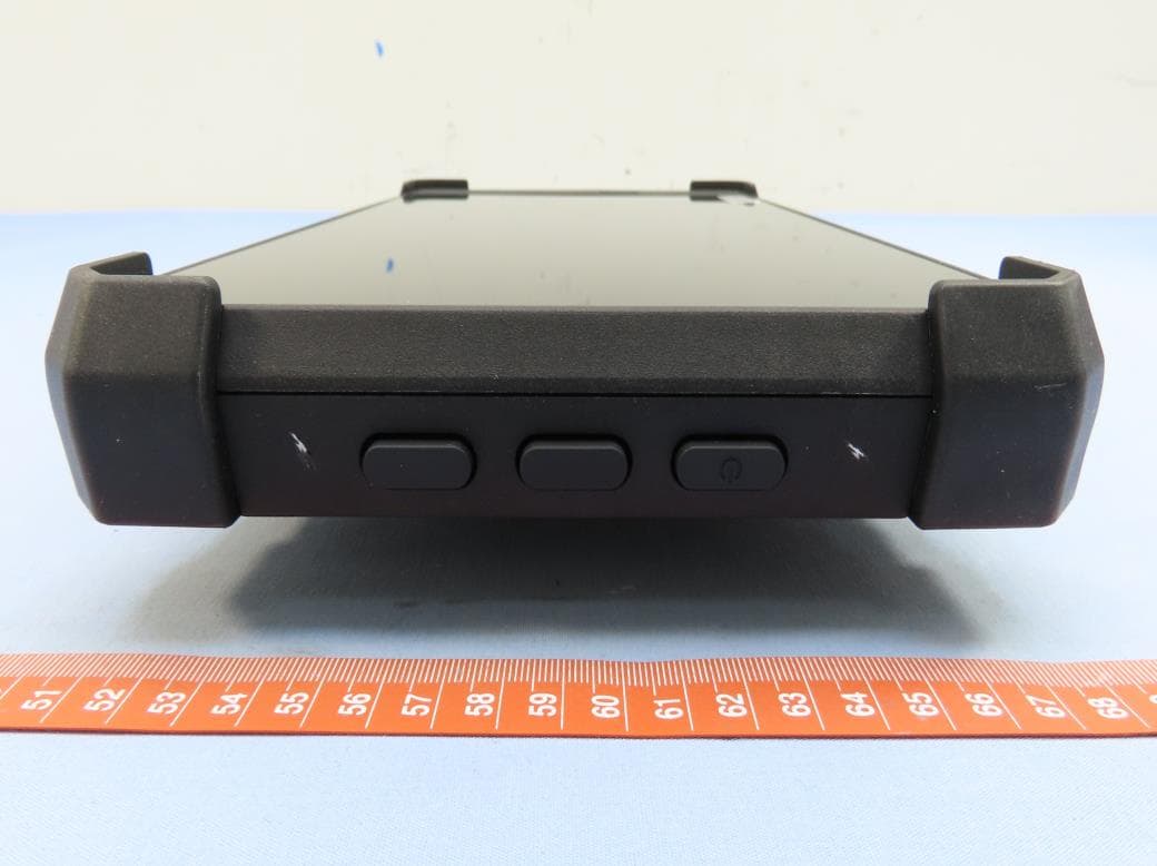
JUP-TD540
Jul 17, 202210 inch Touch Display
Equipment Class
DXX - Part 15 Low Power Communication Device Transmitter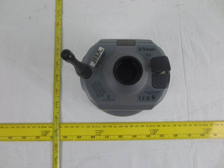
JUP-9091191
Jan 15, 2015GNSS Receiver+900 MHz+Wi-Fi+Bluetooth
Equipment Class
DSS - Part 15 Spread Spectrum Transmitter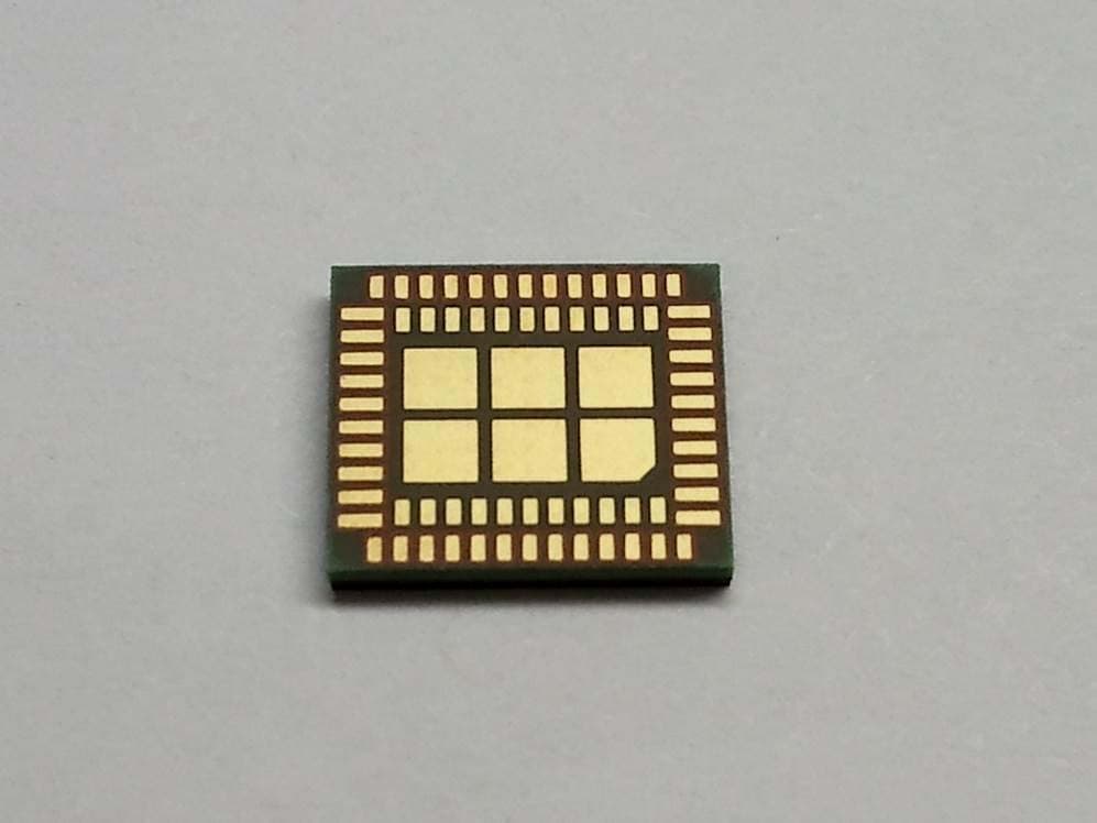
JUP-95807WFBT
Sep 14, 2014WLAN+ Bluetooth Combo Module
Equipment Class
DSS - Part 15 Spread Spectrum Transmitter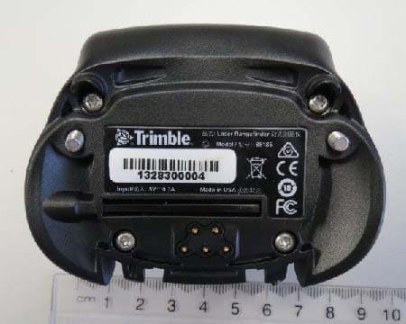
JUP88161
Oct 20, 2013GeoExplorer(R) 7 Series handheld, Geo 7X
Equipment Class
DTS - Digital Transmission System