K3Y-PICO-19001900 MHz Indoor Cellular Base Station
Hughes Network Systems
Click to zoom
Application Details
- Equipment Class
- TNB - Licensed Non-Broadcast Station Transmitter
- Date of Grant
- Jun 14, 2000
- Application Purpose
- Original Equipment
- Date of Application
- May 21, 2000
- Equipment Note
- 1900 MHz Indoor Cellular Base Station
- Frequency Range
- 1850.00000000 - 1990.00000000
- Company
- Hughes Network Systems
- Country
- United States
Documents & Files
Document Text
Text extracted from the exhibit documents filed with the FCC. Open a document above to read the original.
Users Manual
11717 Exploration Lane, Germantown, MD 20876 Tel: (301) 428–5500 Fax: (301) 428 –1868/2830 1026209 – 0001 Revision B February 24, 2000 Installation and Commissioning Manual 1026209 – 0001 Revision Bii Copyright E1999–2000 Hughes Network Systems, a Hughes Electronics Corporation company All rights reserved. This publication and its contents are proprietary to Hughes Network Systems, a Hughes Electronics Corporation company. No part of this publication may be reproduced in any form or by any means without the written permission of Hughes Network Systems, 11717 Exploration Lane, Germantown, Maryland 20876. Hughes Network Systems has made every effort to ensure the correctness and completeness of the material in this document. Hughes Network Systems shall not be liable for errors contained herein. The information in this document is subject to change without notice. Hughes Network Systems makes no warranty of any kind with regard to this material, including, but not limited to, the implied warranties of merchantability and fitness for a particular purpose. Trademarks AIReach is a trademark of Hughes Network Systems. Other trademarks, marks, names, or product names referenced in this publication are the property of their respective owners, and Hughes Network Systems neither endorses nor otherwise sponsors any such products or services referred to herein. 1026209 – 0001 Revision B iii Revision record RevisionDate of issueScope ANovember 8, 1999Initial release BFebruary 24, 2000Added instructions for several additional procedures; minor revisions throughout. 1026209 – 0001 Revision Biv 1026209 – 0001 Revision Bv Contents About this manualxi. . . . . . . . . . . . . . . . . . . . . . . . . . . . . . . . . . . . . . . Important safety information xv. . . . . . . . . . . . . . . . . . . . . . . . . . . . . . 1 Introduction 1–1. . . . . . . . . . . . . . . . . . . . . . . . . . . . . . . . . . . . . . . . . . . 1.1 System components 1–1. . . . . . . . . . . . . . . . . . . . . . . . . . . . . . . . . . . . . . 1.2 System Controller 1–3. . . . . . . . . . . . . . . . . . . . . . . . . . . . . . . . . . . . . . . Hardware 1–3. . . . . . . . . . . . . . . . . . . . . . . . . . . . . . . . . . . . . . . . . . . Software 1–6. . . . . . . . . . . . . . . . . . . . . . . . . . . . . . . . . . . . . . . . . . . . 1.3 Picocell components 1–7. . . . . . . . . . . . . . . . . . . . . . . . . . . . . . . . . . . . . 1.4 Procedural flow chart 1–8. . . . . . . . . . . . . . . . . . . . . . . . . . . . . . . . . . . . 1.5 Tools and materials 1–11. . . . . . . . . . . . . . . . . . . . . . . . . . . . . . . . . . . . . . Required tools 1–11. . . . . . . . . . . . . . . . . . . . . . . . . . . . . . . . . . . . . . . Recommended tools 1–11. . . . . . . . . . . . . . . . . . . . . . . . . . . . . . . . . . . Required materials 1–12. . . . . . . . . . . . . . . . . . . . . . . . . . . . . . . . . . . . Other requirements 1–12. . . . . . . . . . . . . . . . . . . . . . . . . . . . . . . . . . . . 1.6 Configuration options 1–12. . . . . . . . . . . . . . . . . . . . . . . . . . . . . . . . . . . . 2 Adding cards to the System Controller 2–1. . . . . . . . . . . . . . . . . . . . . 2.1 Unpacking the picocells 2–4. . . . . . . . . . . . . . . . . . . . . . . . . . . . . . . . . . 2.2 System Controller card configurations 2–8. . . . . . . . . . . . . . . . . . . . . . . Backplane slot identification 2–8. . . . . . . . . . . . . . . . . . . . . . . . . . . . Standard (factory) configuration 2–9. . . . . . . . . . . . . . . . . . . . . . . . . Fully loaded configuration 2–10. . . . . . . . . . . . . . . . . . . . . . . . . . . . . . 2.3 Adding cards to the System Controller (first steps) 2–11. . . . . . . . . . . . . 2.4 Jumper and DIP switch settings 2–13. . . . . . . . . . . . . . . . . . . . . . . . . . . . Quad T1 card 2–13. . . . . . . . . . . . . . . . . . . . . . . . . . . . . . . . . . . . . . . . TX2000 IP and TX2000 SS7 cards 2–15. . . . . . . . . . . . . . . . . . . . . . . Conference card 2–18. . . . . . . . . . . . . . . . . . . . . . . . . . . . . . . . . . . . . . LAN cards 2–19. . . . . . . . . . . . . . . . . . . . . . . . . . . . . . . . . . . . . . . . . . Modem card 2–19. . . . . . . . . . . . . . . . . . . . . . . . . . . . . . . . . . . . . . . . . Single board computer (SBC) 2–20. . . . . . . . . . . . . . . . . . . . . . . . . . . 2.5 Attaching the bus cables 2–23. . . . . . . . . . . . . . . . . . . . . . . . . . . . . . . . . . 2.6 Adding cards to the System Controller (final steps) 2–24. . . . . . . . . . . . . 2.7 Configuring System Controller cards 2–25. . . . . . . . . . . . . . . . . . . . . . . . Specifying basic card information 2–25. . . . . . . . . . . . . . . . . . . . . . . . 2.8 Verifying the card configuration 2–27. . . . . . . . . . . . . . . . . . . . . . . . . . . . Adding a Quad T1 card 2–30. . . . . . . . . . . . . . . . . . . . . . . . . . . . . . . . Adding a TX2000 or conference card 2–31. . . . . . . . . . . . . . . . . . . . . 1026209 – 0001 Revision Bvi 3 Installing the Controller 3–1. . . . . . . . . . . . . . . . . . . . . . . . . . . . . . . . 3.1 Rack–mount configuration 3–2. . . . . . . . . . . . . . . . . . . . . . . . . . . . . . . . 3.2 Mounting the Controller chassis 3–4. . . . . . . . . . . . . . . . . . . . . . . . . . . . 3.3 Controller cabling 3–5. . . . . . . . . . . . . . . . . . . . . . . . . . . . . . . . . . . . . . . 3.4 Checking System Controller operation 3–6. . . . . . . . . . . . . . . . . . . . . . . 3.5 System cabling 3–7. . . . . . . . . . . . . . . . . . . . . . . . . . . . . . . . . . . . . . . . . 4 Verifying the System Controller configuration 4–1. . . . . . . . . . . . . . . 4.1 Data required 4–1. . . . . . . . . . . . . . . . . . . . . . . . . . . . . . . . . . . . . . . . . . . 4.2 Verifying the System Controller configuration 4–2. . . . . . . . . . . . . . . . . Verifying the site information 4–2. . . . . . . . . . . . . . . . . . . . . . .…
Text truncated - open the document above for the full version.
Attestation Statements
EXHIBIT 3 MANUFACTURING AND PRODUCT INFORMATION MANUFACTURING AND PRODUCT INFROMATION: Type of Authorization: Type Acceptance of 1900MHz Picocell System FCC Identifier:K3Y-PICO-1900 Applicable FCC RULES:FCC Part 2 and Part 24 Manufacturer: Hughes Network Systems 11717 Exploration Lane Germantown, MD 20876 Applicant's Relationship to MFR: same Quantity Production Planned: yes Testing Dates: April 12, to May 10, 2000 Manufacturer's Representative: Mr. John Corrigan 2.983(d) Technical Description The Picocell BTS includes 1 to 4 radio, one scanning receiver, a power supply module and master oscillator, and a BTS controller which includes T1 interface function. Only digital mode operation is supported, using full-rate traffic channels and a Digital Control Channel. The Wireless Station Base Unit is used in the 1900 MHz Domestic Public PCS. The system was tested using TIA/IS-136/IS-138, and will operate in digital mode at a maximum power output of 100 milliwatts. The system was tested for compliance with FCC Rule Part 15 and Part 24. Each radio supports one RF carrier, which has 6 TDMA time slot. In the full-rate digital operation, slot 1&4 is designated as digital channel #1, slot 2&5 as digital channel #2, and slot 3&6 as digital channel #2 and #3 assigned as Digital Traffic Channels (DTCs). The DCCH shall support private system registration functions as specified in IS-136A In call processing, whether it is origination or paging, the Wireless Base Station Unit (WBSU) is a slave unit under the control of the Wireless Office Service Controller (WOSC), which controls one or more Picocell BTSs. The WOSC communicates with each Picocell BTS using a dedicated control time slot (per Picocell BTS) on the T1 interface. This control interface is designated Abis, in that it is similar in nature to the interface between BTS and BSC in the GSM standard. The main duty of the controller function within the Picocell BTS is as a message translator between the air interface messages and the Abis interface messages. For more information on the unit please refer to manual included. 2.1033(c)(3) Instructions/Installation Manual Refer to Exhibit : Installation and Service manua l. 2.1033(c)(4) Types of Emissions DIGITAL= 40K0DXW {TDMA (pi/4 DQPSK)} 2.1033(c)(5) Frequency Range Transmitter: 1930 - 1990 MHz Receiver: 1850 - 1910 MHz 2.1033(c)(6) Range of Operating Power -8dBm to +20dBm (Maximum) .158mW to 100mW (Maximum) 2.1033(c)(7) Maximum Power Rating Section 22.913(a); base transmitters and cellular repeaters must not exceed 500 Watts. 2.1033(c)(8) Applied voltages and currents into the final transistor elements 6 Vdc @ 400 mA 2.1033(c)(9) Tune-up/Optimization Procedure Refer to Exhibit : Installation and Service manual. 2.1033(c)(10) Complete Circuit Diagrams and Functional Block Diagram Refer Exhibits : Schematics and Parts lis t. Confidentiality is requested for these items. 2.1033(c)(10a) Means for Frequency Stabilization A 9.6 MHz Ovenized reference Oscillator (OCXO) is used. The OCXO has frequency drift of +/- 0.25ppm 2.1033(c)(10b) Means for Attenuating Higher Audio Frequencies Built-in filters in Radio and Branching Board. 2.1033(c)(10c) Means for Limiting Modulation DSP 2.1033(c)(10d) Means for Limiting Power DSP 2.1033(c)(11) Equipment Identification A drawing of the equipment identification nameplate appears under Exhibit : PROPOSED FCC ID LABEL FORMA T. 2.1033(c)(12) Photographs Photographs of the equipment, internal and external views, are found in the Exhibit : Eut Photograph s. 2.1033(c)(13) Description of Digital Modulation Techniques Digital Mode: TDMA (p/4 DQPSK) 2.1033(c)(14) Standard Test Conditions The transmitter was tested under the following conditions: Room Temperature: 20 - 23 °C Relative Humidity: 35 - 50% DC Supply Voltage: 24 to 48Vdc The transmitter was aligned and tuned up according to manufacturer’s alignment procedure, prior to testing. All data presented represents the worst case parameter being measured. 2.1033 Description of Various Base Station Configurations Not applicable. 2.1033 Use of Various Power Supplies Ac Adapter Input: 120Vac, 60Hz: Output: 48Vdc Dc power supply form 24 to 48 Vdc
Attestation Statements
1 Frank Coperich Federal Communications Commission Laboratory 7435 Oakland Mills Road, Columbia MD 21046 June 9, 2000 RE: CONFIDENTIALITY REQUEST FCC ID K3Y-PICO-1900 Applicant: Hughes Network Systems Correspondence Reference Number: 14479 731 Confirmation Number: EA97658 Date of Original E-Mail: 06/09/2000 Dear Mr. Coperich I would like to address two of the questions that have been requested in your correspondence letter No: 14479 dated 06/09/2000. Please clarify what "HNS Drawing Number" refers to. 1. Please clarify what "HNS Drawing Number" refers to. The HNS number reffers to the schematic numbers that are included in the EXHABIT 8. 2. Confidentiality Request The part of the above application has been requested confidentiality. The reason for this is that two exhibits (EXHIBIT 8) contain detailed schematics that could lead to technology patent disclosure. The technology is very new and therefore all precautions have to be taken to keep this information confidential from public access. Thank you, for accepting our request. Regards John Rymkiewicz Technical Manager Hughes Network Systems
Block Diagram
EXHIBIT 5 BLOCK DIAGRAM of 1900 MHz PCOCELL SYSTEM RS232 T1/E1 or Ether Link 1 T1/E1 or Ether Link 2 DC Input (24-48V) Auxiliary DC Output (24-48V) PICO-BTS Figure 5.1: PICOCELL 1900 MHz System Architecture PCM or Ether I/F Switch Transceiver 1 (Digital cellular or PCS ) HDLC Processor Downlink Receiver (Digital cellular or PCS ) Branching PCM or Ethernet Link 1 Transceiver 2 (Digital cellular or PCS) Transceiver 3 (Digital cellular or PCS ) Transceiver 4 (Digital cellular or PCS ) DRAMFLASHRISC Processor PCM or Ethernet Link 2 PCM or Ether I/F Figure 5.2: PICOCELL System Internal Architecture
Cover Letter(s)
Frank Coperich Federal Communications Commission Laboratory 7435 Oakland Mills Road, Columbia MD 21046 5/22/2000 FCC ID: K3Y-PICO-1900 Dear Mr. Coperich Please accept the application for the approval of the K3Y-PICO-1900. This is 1900 MHz Wireless Systems that has been found complainant to the FCC Part 24 Type Acceptance requirements. The Files have been submitted electronically to the Federal Communications Commission Laboratory Regards
External Photos
EXHIBIT 4 A EXTERNAL PHOTOS OF 1900 MHz PCOCELL SYSTEM Figure 4.1: Picocell 1900MHz System Front View Figure 4.2: Picocell 1900MHz System Front/Bottom View
External Photos
EXHIBIT 4 B EXTERNAL PHOTOS OF 1900 MHz PCOCELL SYSTEM Figure 4.3: Picocell 1900MHz System Side View Figure 4.4: Picocell 1900MHz System Rear View
ID Label/Location Info
EXHIBIT 1 PICOCELL 1900 MHz SYSTEM LABELS Figure 1.1: FCC / Product Label MADE IN USA US LISTED I.T.E. 4N11 ® C Figure 1.2: 1900 MHz Picocell System Label Area of Placement
ID Label/Location Info
EXHIBIT 2 COMPANY NAME AND MAILING ADDRESS COMPANY NAME AND MAILING ADDRESS: Hughes Network Systems 11717 Exploration Lane Germantown, MD 20876 Telephone Number: (301) 428 – 5500 Fax Number:(301) 428 – 2880
Internal Photos
EXHIBIT 9 INTERNAL PHOTOS OF 1900 MHz PICOCELL SYSTEM Figure 9.1: Picocell System Case with Backplane Figure 9.2: Picocell System with All Modules Figure 9.3: Picocell System with All Modules M Figure 9.4: Picocell System Top View of the Inside Casing Figure 9.5: Picocell System Antenna Ports Figure 9.6: Picocell System Power Supply Module Figure 9.7: Picocell System Power Supply Module Figure 9.8: Picocell System Modules with Casing Figure 9.9: Picocell Module Inside View Figure 9.10: Picocell System Controller Module with Casing Figure 9.11: Picocell System Inside Front View of Controller Module Figure 9.12: Picocell System Inside Back View of Controller Module
Test Report
DateRevRevision RecordApproved 05/12/20001.0Original Release JobApprovalsDate Originator:Logi Balasingam05/12/2000 Hughes Network Systems Approved:John Rymkiewicz05/22/2000 Checked:Title: Type Acceptance Test Plan and Test Report for PICOCELL 1900 MHz System Sheet 1 of 57 CAGE No. No.HNS-22671 Form E75This document created in Microsoft Word Hughes Proprietary II Copyright © 2000 Hughes Network Systems Notice of Proprietary Information This document and its contents are proprietary to Hughes Network Systems and are intended solely for the internal use of Hughes Network Systems. This publication and its contents may not be reproduced or distributed for any other purpose without the written permission of Hughes Network Systems. APPLICATION FOR EQUIPMENT AUTHORIZATION Type Acceptance of a Hughes Network Systems Inc. Indoor Small Size Cellular Base Station PICOCELL 1900MHZ Filing for FCC ID: K3Y-PICO-1900 Title 47 of the CFR, Part 24 HNS REPORT May 18, 2000 PREPARED BY: Hughes Network Systems, Inc. 11717 Exploration Lane Germantown, MD 20876 Hughes Proprietary IIApplication for Type Acceptance Document Number: HNS-22671 No. HNS-22671 Hughes Proprietary II Rev. 1.0 Sheet 2 of 57 Form E75aHughes Network Systems TABLE OF CONTENTS SectionPage 1.0 INTRODUCTION........................................................................................................................... 4 1.1 PURPOSE..................................................................................................................................... 4 1.2 TEST SPECIFICATION................................................................................................................. 4 2.0 MODIFICATIONS STATEMENT ................................................................................................... 5 3.0 ENGINEERING STATEMENT....................................................................................................... 6 4.0 TEST SUMMARY.......................................................................................................................... 7 5.0 DESCRIPTION OF EQUIPMENT UNDER TEST........................................................................... 8 5.1 PRODUCT OVERVIEW ................................................................................................................ 8 5.2 SYSTEM SETUP......................................................................................................................... 10 5.3 SYSTEM CLOCKS...................................................................................................................... 10 5.4 SYSTEM CABLES ...................................................................................................................... 10 6.0 GENERAL TEST CONDITIONS .................................................................................................11 6.1 TEST SITE (GENERAL) .............................................................................................................. 11 6.2 TEST CONFIGURATION ............................................................................................................ 11 6.3 MEASUREMENT INSTRUMENTATION...................................................................................... 12 6.4 MEASUREMENT DETECTOR FUNCTIONS AND BANDWIDTHS ............................................. 12 6.5 FREQUENCIES .......................................................................................................................... 13 6.6 MEASUREMENT EQUIPMENT .................................................................................................. 13 6.7 RADIO TEST SETUP .................................................................................................................. 14 7.0 TEST REQUIREMENTS AND MEASUREMENT PROCEDURES .............................................. 15 7.1 RF OUTPUT POWER ................................................................................................................. 15 7.2 MODULATION CHARACTERSTICS ........................................................................................... 16 7.3 OCCUPIED BANDWIDTH ........................................................................................................... 17 7.4 SPURIOUS EMISSIONS AT ANTENNA TERMINALS ................................................................ 18 7.5 FIELD STRENGTH OF SPURIOUS RADIATION ........................................................................ 20 7.6 FREQUENCY STABILITY ........................................................................................................... 21 7.7 RADIATED SPURIOUS EMISSIONS .......................................................................................... 22 7.7.1 Test Requirements ............................................................................................................................... 22 7.7.2 Test Procedure..................................................................................................................................... 22 7.8 AC CONDUCTED EMISSIONS ...................................................................................................23 7.8.1 Test Requirements ............................................................................................................................... 23 7.8.2 Test Procedure..................................................................................................................................... 23 8.0 TEST RESULTS ......................................................................................................................... 24 8.1 RF OUTPUT POWER ................................................................................................................. 24 8.2 MODULATION CHARACTERSTICS ........................................................................................... 27 8.3 OCCUPIED BANDWIDTH .................................................…
Text truncated - open the document above for the full version.
Test Setup Photos
EXHIBIT 7 TEST SETUP PHOTOS OF 1900 MHz PCOCELL SYSTEM Figure 7.1: Radio Test Setup Figure 7.2: Radio Test Setup Figure 7.3: Radiated Emission OATS Test Setup Figure 7.4: Radiated Emission OATS Test Setup Figure 7.5: Conducted Emission Test Setup
Contact Information
Applicant
Norbert Owona(Sr. Member Technical Staff)
Technical Contact
Hughes Network SystemsJohn Rymkiewicz
[email protected](301) 428-5889
11717 Exploration Lane · Germantown, Maryland · United States
Technical Specifications
| # | Rule Parts | Frequency Range | Power Output | Emission | Tolerance |
|---|---|---|---|---|---|
| 1 | 24E | 1.85 GHz - 1.99 GHz | 100.00 mW | 40K0DXW | 0.2500000000 ppm |
Other Applications from Hughes Network Systems
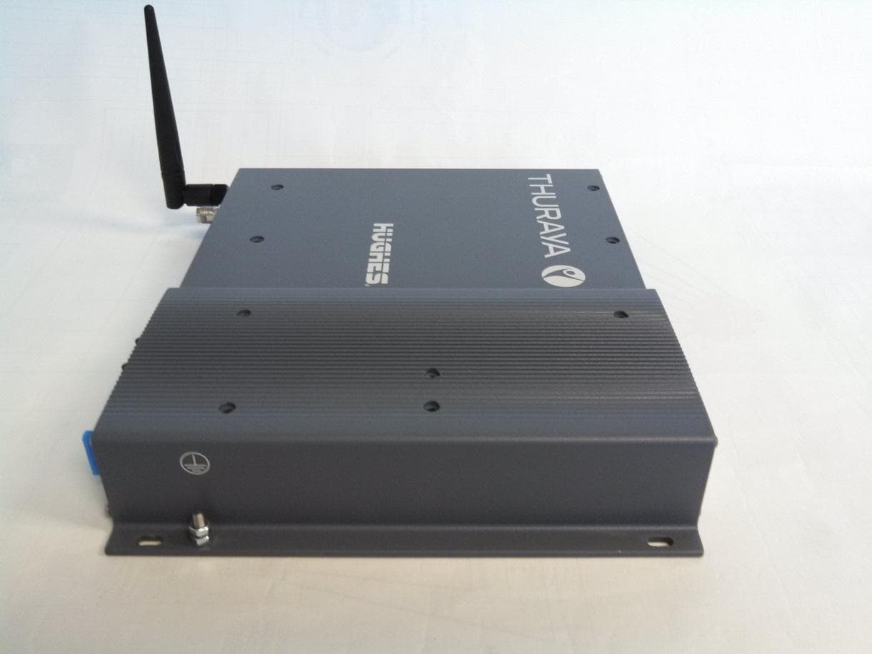
K3YHNS9105
Mar 12, 2015Thuraya IP+ Broadband Satellite IP Modem with WLAN
Equipment Class
DTS - Digital Transmission System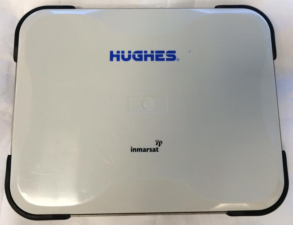
K3YHNS9211
Sep 18, 2014Satellite Terminal with WLAN functionality
Equipment Class
DTS - Digital Transmission System
K3YHNS9202
Jul 21, 2011Land Portable Terminal
Equipment Class
DTS - Digital Transmission System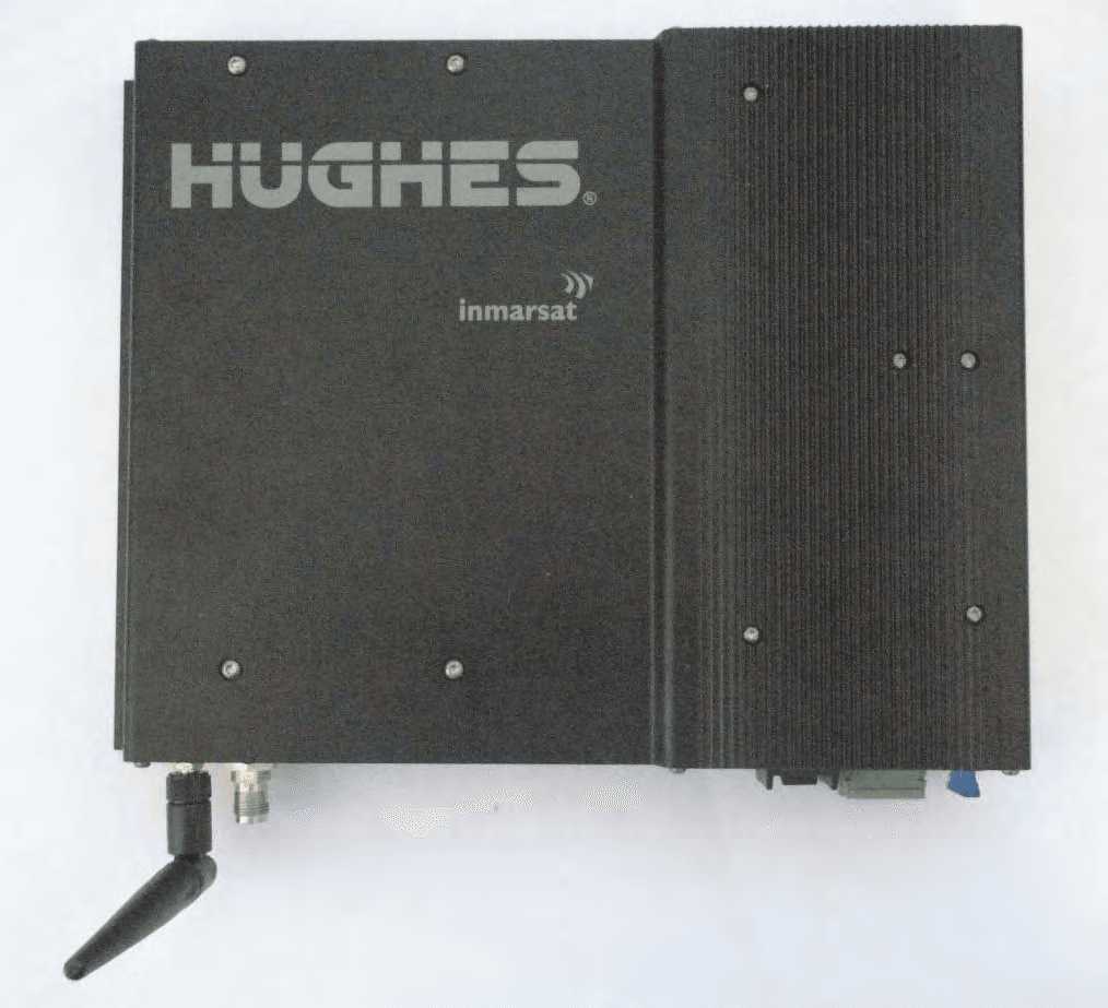
K3YHNS9450
Sep 13, 2010Land Mobile Terminal
Equipment Class
DTS - Digital Transmission System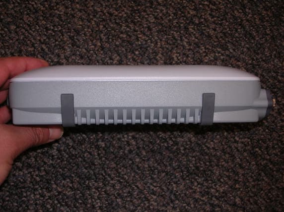
K3YHNS9103
Jan 13, 2008Broadband Satellite IP Modem
Equipment Class
DTS - Digital Transmission System