K3YHNS9103Broadband Satellite IP Modem
Hughes Network Systems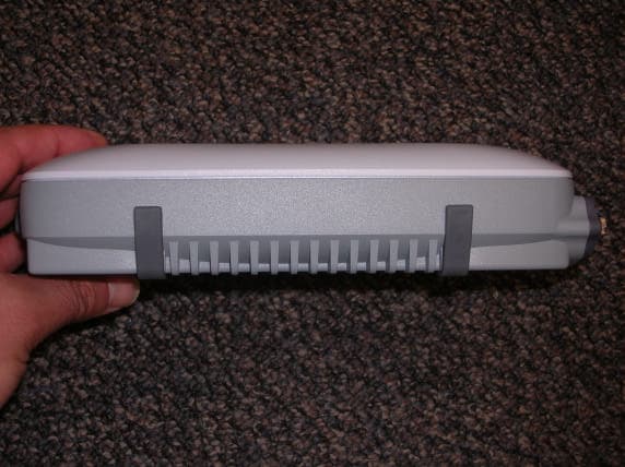
Click to zoom
Application Details
- Equipment Class
- DTS - Digital Transmission System
- Date of Grant
- Jan 13, 2008
- Application Purpose
- Original Equipment
- Date of Application
- Jan 11, 2008
- Equipment Note
- Broadband Satellite IP Modem
- Frequency Range
- 2412.00000000 - 2462.00000000
- Company
- Hughes Network Systems
- Country
- United States
Documents & Files
Document Text
Text extracted from the exhibit documents filed with the FCC. Open a document above to read the original.
Users Manual
UserGuide ThurayaIP Satellite Modem Revision B 3500175-0001 Copyright 2008 Hughes Network Systems, LLC. All rights reserved. This publication and its contents are proprietary to Hughes Network Systems, LLC. No part of this publication may be reproduced in any form or by any means without the written permission of Hughes Network Systems, LLC., 11717 Exploration Lane, Germantown, Maryland 20876.Hughes Network Systems, LLC., has made every effort to ensure the correctness and completenessof the material in this document. Hughes Network Systems, LLC., shall not be liable for errors contained herein. The information in this document is subject to change without notice. Hughes Network Systems, LLC. makes no warranty of any kind with regard tothis material, including, but not limited to, the implied warranties of merchantability and fitness for a particular purpose. Trademarks All trademarks, marks, names, or product names referenced in this publication are the property of their respective owners, and Hughes Network Systems, LLC. neither endorses nor otherwise sponsors any such products or services referred to herein.HUGHES and Hughes Network Systems are trademarks of Hughes Network Systems, LLC.THURAYA trademark is the sole and exclusive property of Thuraya Satellite Telecommunications Company. ThurayaIP Satellite Modem User Manuali Safety Information For your safety and protection, read this entire user manual before you attempt to useThurayaIPSatellite Modem. In particular, read this safety section carefully. Keep this safety information where you can refer to if necessary. Warning Symbols Used in this Manual This section introduces the various types of warnings used in this document to alert you to possible safety hazards. WARNING Potential radio frequency (RF) hazard. Where you see this alert symbol and WARNING heading, strictly follow the warning instructions to avoid injury to eyes or other personal injury. WARNING Whereyou see this alert symbol and WARNING heading, strictly follow the warning instructions to avoid personal injury. DANGER Electric shock hazard: Where you see this alert symbol and DANGER heading, strictly follow the warning instructions to avoid electric shock injury or death. iiThurayaIP Satellite Modem User Manual Warnings forTHURAYAIP Do not stand in front of the Antenna. This device emitsradio frequency energy when in the transmit mode. To avoid injury, do not place head or other body parts in front of the satellite antenna when system is operational. Maintain a distance of one meter away from the front of ThurayaIP’s antenna. Properly ground the Antenna Failure to properly ground the optional external antenna may result in severe personal injury or death. Do not attempt to ground the optional external antenna unless you have the skills to do so in accordance with local electrical codes. Do not operate during Electrical Storms Operation ofThurayaIPduring electrical storms may result in severe personal injury or death. DisconnectThurayaIPfrom computer and store unit indoors if lightning is anticipated in the area of operation. General Handle yourThurayaIPwith care. The enclosure is weather resistant per IEC 60529 IP55. However, do not submerge the unit or expose it to severe rainstorms. Avoid exposing your ThurayaIPto extreme hot or cold temperatures. The operating temperature range ofThurayaIPis -10ºC to +55ºC.Avoid placing yourThurayaIPclose to cigarettes, open flames or any source of heat. Changes or modifications toThurayaIPnot expressly approved by Hughes Network Systems could void your authority to operate this equipment. Use a soft damp cloth only toclean yourThurayaIP. To avoid impaired Modem performance, please ensure your ThurayaIP’s antenna is not damaged or covered with foreign material like paint or labelling.This equipment must not be co- located or operatedin conjunction with any other antenna or transmitter. When inserting the SIM, do not bend the SIM or damage the contacts in any way. When connecting the interface cables, do not use excessive force. ThurayaIP Satellite Modem User Manualiii In the vicinity of blasting work and in explosive environments Never useThurayaIPwhere blasting work is in progress. Observe all restrictions and follow any regulations or rules. Areas with a potentially explosive environment are often, but not always, clearly marked. Do not useThurayaIPwhile at a petrol filling station. Do not use near fuel or chemicals. Qualified service Do not attempt to disassemble yourThurayaIP.Th urayaIP does not contain consumer-serviceable components. Only qualified service personnel may install or repair equipment. Batteries and accessories Use approved batteries (HNS P/N 3500108-0001) and accessories only. Use of non-approved accessories may result in loss of performance, damage toThurayaIP, fire, electric shock or injury. AC Mains power adapter (HNS P/N 3500114-0001) is for indoor use only. It has an indoor operating temperature range of- 10ºC to +55ºC and provides an output voltage of 12 VDC. The storage capability of the battery decreases when operated below 0ºC. If the battery is charged at too high a temperature, this will be indicated on the LCD display. Battery Door To ensure safety, ensurethatthe battery door is properly closed and latched at all times during operation. To close the battery door, hook the battery door tab under the edge of the largeopening in theenclosurenear the data connector ports. Firmly press the battery door into the opening. The seal around the battery door should snugly fit between the door and the enclosurewith no pinch points visible. Once a good seal has been made, screw the retaining fastener into the enclosure until hand tight. Connecting devices Never connect incompatible products. When connecting ThurayaIPto any other device, read thedevice’s User Manual for detailed safety instructions. ivThurayaIP Satellite Modem User Manual Pacemakers The various brands and models of cardiac pacemakers available ex…
Text truncated - open the document above for the full version.
Cover Letter(s)
HiiQiiLS. NETWORK SYSTEMS Nemko Canada Inc 303 River Road Ottawa, Ontario, Canada KIV lH2 Attn: Director of Certification Authority to Act as Anent Model no: Hughes 91 03 Description: Broadband Satellite IP Modem FCC ID: K3YHNS9103 On our behalf, I appoint Peter Sroka, Hughes Network Systems, 9605 Scranton Road, Suite 500, San Diego, CA 92121 to act as our agent in the preparation of this application for'equipment certification. I certify that submitted documents properly describe the device or system for which equipment certification is sought. I also certify that each unit manufactured, imported or marketed, as defined in the Federal Communications Commission's regulations will have affixed to it a label identical to that submitted for approval with this application. For instances where our authorized agent signs the application for certification on our behalf, I acknowledge that all responsibility for complying with the terms and conditions for certification, as specified by Nemko Canada Inc, still resides with Hughes Network Systems, 11 71 7 Exploration Lane, Gerrnantown, MD 20876. Dated this 2@ Day of December Agency agreement expiration date: December 19,2008 n By: John Rymkiewicz Printed Title: Regulatory Manager On behalf of: Hughes Network Systems Telephone: 301-428-5889 , . Corporate Offices 11717 Explorat~on Lane Germantown, MD 20876 USA phone 301.428.5500 fax 301.428.1868 www.hns.com
Cover Letter(s)
November 14, 2007 Nemko 11696 Sorrento Valley Rd. San Diego CA, 92121 USA Re: Request of Confidentiality for FCC ID#: K3YHNS9103 Pursuant to Sections 0.457(d)(I)(ii) and 0.459 of the Commission’s Rules, the Applicant hereby requests confidential treatment of information accompanying as outlined below: • Schematics, • Parts List, • Operating Description, • Block Diagrams The above materials contain trade secrets and proprietary information not customarily released to the public. The public disclosure of these matters might be harmful to the Applicant and provide unjustified benefits to its competitors. The Applicant understands that pursuant to Rule 0.457(d)(I)(ii), disclosure of this Application and all accompanying documentation will not be made before the date of the Grant for this Application. Sincerely,
Cover Letter(s)
Nemko Canada Inc 303 River Road Ottawa, Ontario, Canada K1V 1H2 Attn: Director of Certification RE: K3YHNS9103 Authority to Act as Agent On our behalf, I appoint Nemko USA, 11696 Sorrento Valley Road, San Diego, CA to act as our agent in the preparation of this application for equipment certification. I certify that submitted documents properly describe the device or system for which equipment certification is sought. I also certify that each unit manufactured, imported or marketed, as defined in the Federal Communications Commission’s regulations will have affixed to it a label identical to that submitted for approval with this application. For instances where our authorized agent signs the application for certification on our behalf, I acknowledge that all responsibility for complying with the terms and conditions for certification, as specified by Nemko Canada Inc, still resides with Hughes Network Systems, 11717 Exploration Lane, Germantown, MD 20876.
ID Label/Location Info
E E 3500191 SCALE DRAWING SCALE 3500191 D 71681 REV DRAWING NO CAGE NO SIZE A HUGHES ELECTRONICS COMPANY 10450 PACIFIC CENTER COURT SAN DIEGO, CA 92121 REV DAT EAPPROVED SEE SHEET 1 DESCRIPTION 1 DWG NO 12 3 4 5 6 78 A B C D 8 7 6 5 43 D C B A This drawing is the sole property of HUGHES NETWORK SYSTEMS and shall not be reproduced, copied or issued as the basis of manufacture or sale of apparatus without permission and shall be returned with quotation, at termination of contract or on demand of HUGHES NETWORK SYSTEMS. PRO/E CAD GENERATED DRAWING- DO NOT CHANGE MANUALLY DO NOT SCALE DRAWING SH 3 SHEET 3 OF 3 REVISIONS 3500191-0041 ARTWORK REV. E 2 3500191-0002 PART REV. E Manufactured in the USA by Hughes. Wi-Fi FCC ID: K3YHNS9103 This device complies with Part 15 of the FCC Rules. Operation is subject to the following two conditions: (1) This device may not cause harmful interference, and (2) This device must accept any interference received, including interference that may cause undesired operation. MCN: 3500090-XXXX REV: XX IMEI: XXXXXX-XX-XXXXXX-X Model: 9103 ThurayaIP Use only power adapters listed in the user guide Manufactured in the USA by Hughes. Wi-Fi FCC ID: K3YHNS9103 This device complies with Part 15 of the FCC Rules. Operation is subject to the following two conditions: (1) This device may not cause harmful interference, and (2) This device must accept any interference received, including interference that may cause undesired operation. MCN: 3500090-XXXX REV: XX IMEI: XXXXXX-XX-XXXXXX-X Model: 9103 ThurayaIP Use only power adapters listed in the user guide
Internal Photos
with shield without shield
RF Exposure Info
Prediction of MPE limit at a given distance Equation from page 18 of OET Bulletin 65, Edition 97-01 where:S = power density P = power input to the antenna G = power gain of the antenna in the direction of interest relative to an isotropic radiator R = distance to the center of radiation of the antenna Maximum peak output power --Conducted16.2dBm 0.042(W) Antenna gain(typical):5.00(dBi) Maximum antenna gain:3.16(numeric) Prediction distance:20.00(cm) Prediction frequency:2412.0(MHz) Limit from table below:1(mW/cm^2) Power density at prediction frequency:0.026(mW/cm^2) EUT complies FCC/LSGAC Local Official’s Guide to RF A LOCAL GOVERNMENT OFFICIAL'S GUIDE TO TRANSMITTING ANTENNA RF EMISSION SAFETY: RULES, PROCEDURES, AND PRACTICAL GUIDANCE 2 4R PG S π = Prediction of MPE limit at a given distance Equation from page 18 of OET Bulletin 65, Edition 97-01where: S = power density P = power input to the antennaG = power gain of the antenna in the direction of interest relative to an isotropic radiatorR = distance to the center of radiation of the antenna Maximum peak output power --Conducted 30.48 dBm 1.117 (W) Antenna gain(typical): 8.50 (dBi) Maximum antenna gain: 7.08 (numeric) Prediction distance: 100.00 (cm) Prediction frequency: 1643.50 (MHz) Limit from table below: 1 (mW/cm^2) Power density at prediction frequency: 0.063 (mW/cm^2) EUT complies FCC/LSGAC Local Official’s Guide to RFA LOCAL GOVERNMENT OFFICIAL'S GUIDE TO TRANSMITTING ANTENNA RFEMISSION SAFETY: RULES, PROCEDURES, AND PRACTICAL GUIDANCE 2 4 R PG S π =
Test Report
Nemko USA, Inc. 11696 Sorrento Valley Rd., Suite F San Diego, CA 92121-1024 Phone (858) 755-5525 Fax (858) 452-1810 Certification Test Report: 2007 128454 Thuraya FCC Project number: 8454-1 Equipment Under Test (EUT): Broadband Satellite IP Modem Model: Hughes 9103 FCC ID: K3YHNS9103 In Accordance With: FCC Part 15 Subpart C, 15.247 For: HUGHES NETWORK SYSTEMS 9605 SCRANTON ROAD, SUITE 500 SAN DIEGO, CA 92121 Tested By: Nemko USA Inc. 11696 Sorrento Valley Road, Suite F San Diego, CA 92121 Authorized By: FR Fleury FR Fleury, Manager Date: DECEMBER 20, 2007 Total Number of Pages: 49 Nemko USA, Inc. 11696 Sorrento Valley Road, Suite F, San Diego, CA 92121 Phone (858) 755-5525 Fax (858) 452-1810 Report Number: 2007 128454 Thuraya FCC FCC ID: K37HNS9103 Specification: FCC Part 15 Subpart C, 15.247 Page 2 of 49 Report Release History: REVISION DATE COMMENTS - December 20, 2007 Prepared By: Alan Laudani - December 20, 2007 Initial Release: F. Fleury Note that the results contained in this report relate only to the items tested and were obtained in the period between the date of initial receipt of samples and the date of issue of the report. This test report has been completed in accordance with the requirements of ISO/IEC 17025. Nemko USA Inc. authorizes the applicant to reproduce this report provided it is reproduced in its entirety and for use by the company’s employees only. Any use which a third party makes of this report, or any reliance on or decisions to be made based on it, are the responsibility of such third parties. Nemko USA Inc. accepts no responsibility for damages, if any, suffered by any third party as a result of decisions made or actions based on this report. TESTED BY: Date: December 20, 2007 Alan Laudani, EMC Test Engineer Nemko USA, Inc. 11696 Sorrento Valley Road, Suite F, San Diego, CA 92121 Phone (858) 755-5525 Fax (858) 452-1810 Report Number: 2007 128454 Thuraya FCC FCC ID: K37HNS9103 Specification: FCC Part 15 Subpart C, 15.247 Page 3 of 49 TABLE OF CONTENTS 1. ADMINISTRATIVE DATA..............................................................................................5 1.1. Administrative Data.................................................................................................................5 2. SYSTEM CONFIGURATION.........................................................................................6 2.1. System Components and Power Cables..................................................................................6 2.2. Device Interconnection and I/O Cables.....................................................................................6 2.3. Description and Method of Exercising the EUT.........................................................................7 2.4. Design Modifications for Compliance........................................................................................7 2.5. Product Identification..............................................................................................................9 2.6. Technical Specifications of the EUT.........................................................................................9 3. Description of Testing Methods...............................................................................10 3.1. Test Methods.......................................................................................................................10 3.2. Specifications.......................................................................................................................10 3.3. Deviations From Laboratory Test Procedures.........................................................................10 3.4. Test Environment.................................................................................................................10 3.5. Test Equipment....................................................................................................................11 4. Observations.................................................................................................................12 4.1. Modifications Performed During Assessment..........................................................................12 4.2. Record Of Technical Judgements..........................................................................................12 4.3. EUT Parameters Affecting Compliance..................................................................................12 4.4. Test Deleted.........................................................................................................................12 4.5. Additional Observations........................................................................................................12 5. Results Summary.........................................................................................................13 5.1. Test Results.........................................................................................................................13 Appendix A:...............................................................................................................................14 6. Test Results...................................................................................................................14 6.1. Conductive Maximum peak output power...............................................................................14 6.2. Out-of-band Emissions / Radiated Emissions within Restricted Bands......................................18 6.3. Bandedge Measurements.....................................................................................................30 6.4. Power Spectral Density.........................................................................................................36 6.5. Minimum 6dB RF Bandwidth.................................................................................................40 6.6. Receiver Spurious Emissions.............................................................…
Text truncated - open the document above for the full version.
Contact Information
Applicant
Norbert Owona(Sr. Member Technical Staff)
Technical Contact
Hughes Network SystemsPeter Sroka
[email protected]858-452-4664
9605 Scranton Rd · San Diego · United States
Non-Technical Contact
Hughes Network SystemsPeter Sroka
[email protected]858-452-4664
Test Firm
Nemko USA, Inc.Rhonda Saxon
Technical Specifications
| # | Rule Parts | Frequency Range | Power Output |
|---|---|---|---|
| 1 | 15C | 2.41 GHz - 2.46 GHz | 42.00 mW |
Other Applications from Hughes Network Systems
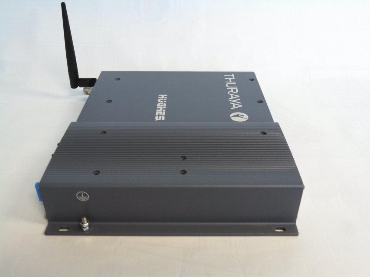
K3YHNS9105
Mar 12, 2015Thuraya IP+ Broadband Satellite IP Modem with WLAN
Equipment Class
DTS - Digital Transmission System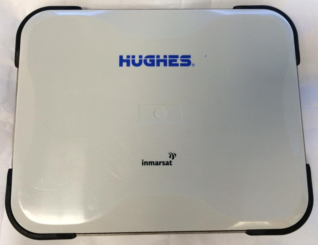
K3YHNS9211
Sep 18, 2014Satellite Terminal with WLAN functionality
Equipment Class
DTS - Digital Transmission System
K3YHNS9202
Jul 21, 2011Land Portable Terminal
Equipment Class
DTS - Digital Transmission System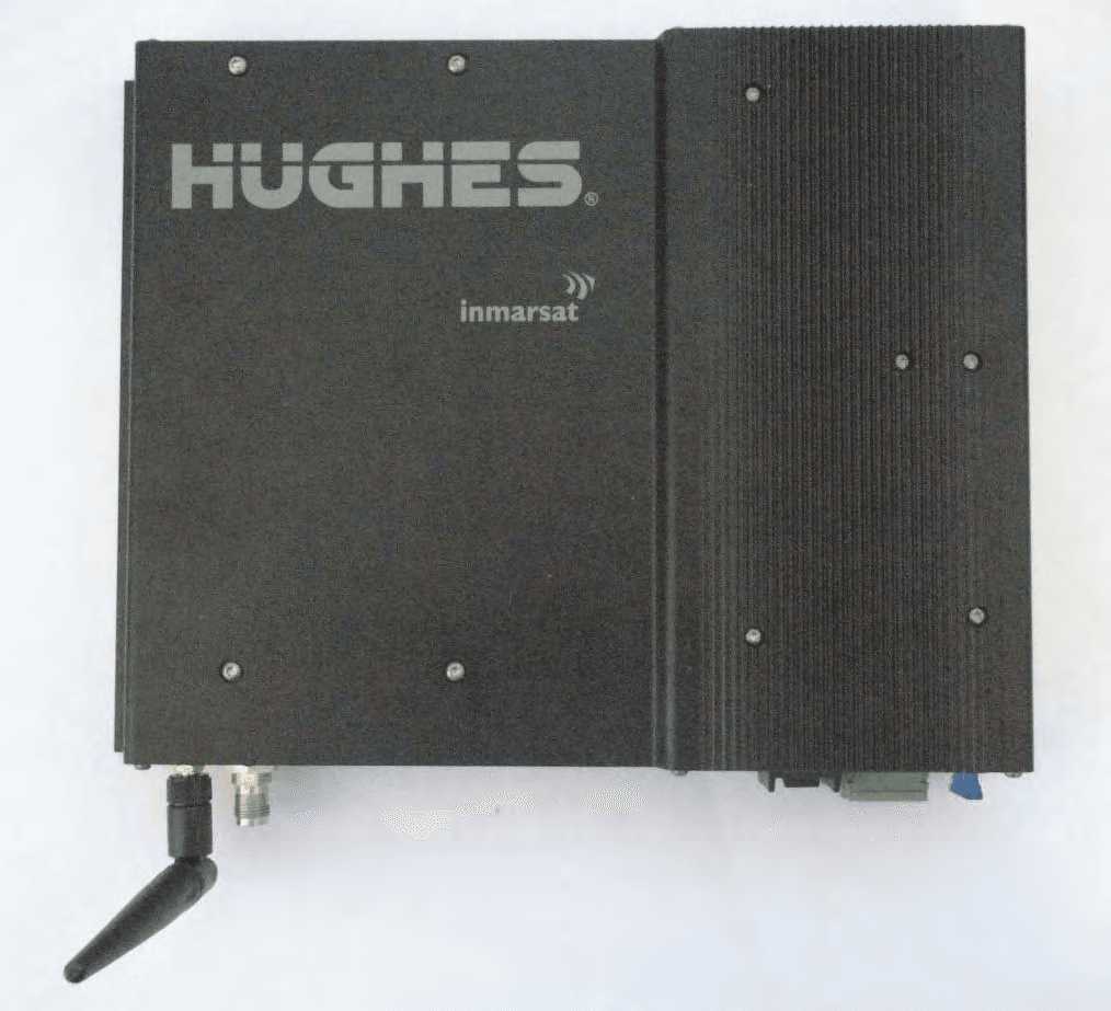
K3YHNS9450
Sep 13, 2010Land Mobile Terminal
Equipment Class
DTS - Digital Transmission System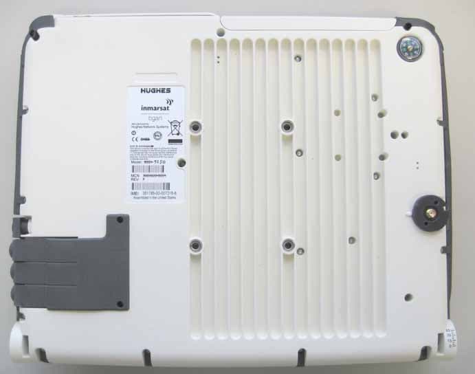
K3YHNS9250
Apr 24, 2007Satellite Terminal
Equipment Class
TNB - Licensed Non-Broadcast Station Transmitter