K3YHNS9101Satellite IP Modem
Hughes Network Systems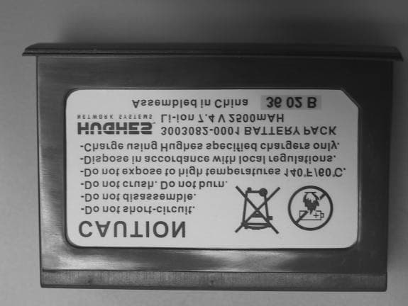
Click to zoom
Application Details
- Equipment Class
- DSS - Part 15 Spread Spectrum Transmitter
- Date of Grant
- Feb 09, 2003
- Application Purpose
- Original Equipment
- Date of Application
- Feb 09, 2003
- Equipment Note
- Satellite IP Modem
- Frequency Range
- 2402.00000000 - 2480.00000000
- Company
- Hughes Network Systems
- Country
- United States
Documents & Files
Document Text
Text extracted from the exhibit documents filed with the FCC. Open a document above to read the original.
Users Manual
User Manual Satellite IP Modem Copyright 2002 Hughes Network Systems, Inc., A wholly owned subsidiary of Hughes Electronics Corporation All rights reserved. This publication and its contents are proprietary to Hughes Network Systems, Inc., a wholly owned subsidiary of Hughes Electronics Corporation. No part of this publication may be reproduced in any form or by any means without the written permission of Hughes Network Systems, Inc., 11717 Exploration Lane, Germantown, Maryland 20876. Hughes Network Systems, Inc., has made every effort to ensure the correctness and completeness of the material in this document. Hughes Network Systems, Inc., shall not be liable for errors contained herein. The information in this document is subject to change without notice. Hughes Network Systems, Inc. makes no warranty of any kind with regard to this material, including, but not limited to, the implied warranties of merchantability and fitness for a particular purpose. Trademarks All trademarks, marks, names, or product names referenced in this publication are the property of their respective owners, and Hughes Network Systems, Inc. neither endorses nor otherwise sponsors any such products or services referred to herein. HUGHES and Hughes Network Systems are trademarks of Hughes Electronics Corporation. Bluetooth is a trademark owned by Bluetooth SIG, Inc. and is used by Hughes Network Systems under license. INMARSAT is a trademark of the International Mobile Satellite Organisation. The Inmarsat LOGO and the trademark BGAN are trademarks of Inmarsat (IP) Company Limited. All trademarks are licensed to Inmarsat Limited. SAFETY INFORMATION For your safety and protection, read this entire operations manual before you attempt to use the Regional BGAN Satellite IP Modem. In particular, read this safety section carefully. Keep this safety information where you can refer to it if necessary. WARNING SYMBOLS USED IN THIS MANUAL This section introduces the various types of warnings used in this document to alert you to possible safety hazards. WARNING Potential radio Frequency (RF) hazard. Where you see this alert symbol and WARNING heading, strictly follow the warning instructions to avoid injury to eyes or other personal injury. WARNING Where you see this alert symbol and WARNING heading, strictly follow the warning instructions to avoid personal injury. DANGER Electric shock hazard: Where you see this alert symbol and DANGER heading, strictly follow the warning instructions to avoid electric shock injury or death. WARNINGS FOR THE SATELLITE IP MODEM Do not stand in front of the Antenna. This device emits radio frequency energy when in the transmit mode. To avoid injury, do not place head or other body parts in front of the satellite antenna when system is operational. Maintain a distance of one meter away from the front of the Satellite IP Modem’s antenna. Properly ground the Antenna Failure to properly ground the optional external antenna may result in severe personal injury or death. Do not attempt to ground the optional external antenna unless you have the skills to do so in accordance with local electrical codes. Regional BGAN Satellite IP Modem User Manual i Do not operate during Electrical Storms Operation of the Satellite IP Modem during electrical storms may result in severe personal injury or death. Disconnect the Satellite IP Modem from computer and store unit indoors if lightning is anticipated in the area of operation. General Handle your Satellite IP Modem with care. The enclosure is weather resistant per IEC 60529 IP44; however do not submerge the unit or expose it to severe rain storms. Avoid exposing your Satellite IP Modem to extreme hot or cold temperatures. The operating temperature range of the Satellite IP Modem is -10ºC to +55ºC. Avoid placing your Satellite IP Modem close to cigarettes, open flames or any source of heat. Changes or modifications to the Satellite IP Modem not expressly approved by Hughes Network Systems could void your authority to operate this equipment. Only use a soft damp cloth to clean your Satellite IP Modem. To avoid impaired Modem performance, please ensure your Satellite IP Modem’s antenna is not damaged or covered with foreign material like paint or labelling. When inserting the SIM, do not bend the SIM or damage the contacts in any way. When connecting the interface cables, do not use excessive force. In the vicinity of blasting work and in explosive environments Never use the Satellite IP Modem where blasting work is in progress. Observe all restrictions and follow any regulations or rules. Areas with a potentially explosive environment are often, but not always, clearly marked. Do not use the Satellite IP Modem while at a petrol filling station. Do not use near fuel or chemicals. Qualified service Do not attempt to disassemble your Satellite IP Modem. The Satellite IP Modem does not contain consumer serviceable components. Only qualified service personnel may install or repair equipment. ii Regional BGAN Satellite IP Modem User Manual Batteries and accessories Use approved batteries (HNS P/N 3003082-0001) and accessories only. Use of non-approved accessories may result in loss of performance, damage to the Satellite IP Modem, fire, electric shock or injury. AC Mains power adapter (FRIWO Model SDA5012) is for indoor use only. It has an indoor operating temperature range of -10ºC to +55ºC and provides an output voltage of 12 VDC. The storage capability of the battery decreases when operated below -10ºC. If the battery is charged at too high a temperature, the battery light will flash red. Connecting devices Never connect incompatible products. When connecting the Satellite IP Modem to any other device, read the device’s User Manual for detailed safety instructions. Pacemakers The various brands and models of cardiac pacemakers available exhibit a wide range of immunity levels to radio signals. Therefore, people who wear a cardiac pacemaker and who want to us…
Text truncated - open the document above for the full version.
Users Manual
User Manual Satellite IP Modem Copyright 2002 Hughes Network Systems, Inc., A wholly owned subsidiary of Hughes Electronics Corporation All rights reserved. This publication and its contents are proprietary to Hughes Network Systems, Inc., a wholly owned subsidiary of Hughes Electronics Corporation. No part of this publication may be reproduced in any form or by any means without the written permission of Hughes Network Systems, Inc., 11717 Exploration Lane, Germantown, Maryland 20876. Hughes Network Systems, Inc., has made every effort to ensure the correctness and completeness of the material in this document. Hughes Network Systems, Inc., shall not be liable for errors contained herein. The information in this document is subject to change without notice. Hughes Network Systems, Inc. makes no warranty of any kind with regard to this material, including, but not limited to, the implied warranties of merchantability and fitness for a particular purpose. Trademarks All trademarks, marks, names, or product names referenced in this publication are the property of their respective owners, and Hughes Network Systems, Inc. neither endorses nor otherwise sponsors any such products or services referred to herein. HUGHES and Hughes Network Systems are trademarks of Hughes Electronics Corporation. Bluetooth is a trademark owned by Bluetooth SIG, Inc. and is used by Hughes Network Systems under license. INMARSAT is a trademark of the International Mobile Satellite Organisation. The Inmarsat LOGO and the trademark BGAN are trademarks of Inmarsat (IP) Company Limited. All trademarks are licensed to Inmarsat Limited. SAFETY INFORMATION For your safety and protection, read this entire operations manual before you attempt to use the Regional BGAN Satellite IP Modem. In particular, read this safety section carefully. Keep this safety information where you can refer to it if necessary. WARNING SYMBOLS USED IN THIS MANUAL This section introduces the various types of warnings used in this document to alert you to possible safety hazards. WARNING Potential radio Frequency (RF) hazard. Where you see this alert symbol and WARNING heading, strictly follow the warning instructions to avoid injury to eyes or other personal injury. WARNING Where you see this alert symbol and WARNING heading, strictly follow the warning instructions to avoid personal injury. DANGER Electric shock hazard: Where you see this alert symbol and DANGER heading, strictly follow the warning instructions to avoid electric shock injury or death. WARNINGS FOR THE SATELLITE IP MODEM Do not stand in front of the Antenna. This device emits radio frequency energy when in the transmit mode. To avoid injury, do not place head or other body parts in front of the satellite antenna when system is operational. Maintain a distance of one meter away from the front of the Satellite IP Modem’s antenna. Properly ground the Antenna Failure to properly ground the optional external antenna may result in severe personal injury or death. Do not attempt to ground the optional external antenna unless you have the skills to do so in accordance with local electrical codes. Regional BGAN Satellite IP Modem User Manual i Do not operate during Electrical Storms Operation of the Satellite IP Modem during electrical storms may result in severe personal injury or death. Disconnect the Satellite IP Modem from computer and store unit indoors if lightning is anticipated in the area of operation. General Handle your Satellite IP Modem with care. The enclosure is weather resistant per IEC 60529 IP44; however do not submerge the unit or expose it to severe rain storms. Avoid exposing your Satellite IP Modem to extreme hot or cold temperatures. The operating temperature range of the Satellite IP Modem is -10ºC to +55ºC. Avoid placing your Satellite IP Modem close to cigarettes, open flames or any source of heat. Changes or modifications to the Satellite IP Modem not expressly approved by Hughes Network Systems could void your authority to operate this equipment. Only use a soft damp cloth to clean your Satellite IP Modem. To avoid impaired Modem performance, please ensure your Satellite IP Modem’s antenna is not damaged or covered with foreign material like paint or labelling. When inserting the SIM, do not bend the SIM or damage the contacts in any way. When connecting the interface cables, do not use excessive force. In the vicinity of blasting work and in explosive environments Never use the Satellite IP Modem where blasting work is in progress. Observe all restrictions and follow any regulations or rules. Areas with a potentially explosive environment are often, but not always, clearly marked. Do not use the Satellite IP Modem while at a petrol filling station. Do not use near fuel or chemicals. Qualified service Do not attempt to disassemble your Satellite IP Modem. The Satellite IP Modem does not contain consumer serviceable components. Only qualified service personnel may install or repair equipment. ii Regional BGAN Satellite IP Modem User Manual Batteries and accessories Use approved batteries (HNS P/N 3003082-0001) and accessories only. Use of non-approved accessories may result in loss of performance, damage to the Satellite IP Modem, fire, electric shock or injury. AC Mains power adapter (FRIWO Model SDA5012) is for indoor use only. It has an indoor operating temperature range of -10ºC to +55ºC and provides an output voltage of 12 VDC. The storage capability of the battery decreases when operated below -10ºC. If the battery is charged at too high a temperature, the battery light will flash red. Connecting devices Never connect incompatible products. When connecting the Satellite IP Modem to any other device, read the device’s User Manual for detailed safety instructions. Pacemakers The various brands and models of cardiac pacemakers available exhibit a wide range of immunity levels to radio signals. Therefore, people who wear a cardiac pacemaker and who want to us…
Text truncated - open the document above for the full version.
Block Diagram
1.0 HUGHES MODEL 9101 REGIONAL-BGAN SATELLITE IP MODEM: OSCILLATOR FREQUENCIES & CLOCK DISTRIBUTION 1.1 RF BLOCK DIAGRAM Figure 1, is the proposed approach to implementing the IEET RF. I/Q MOD I/Q DEMOD Power Detection and control SAT PA SAT TX Power Sample to BB RH & LH CP ANT RX IF SAW 492 MHz RCVR 13 MHz VCTCXO Rcvr AFC 13 MHZ to BB AGC prog SAT TX: 1626.5 to 1660.5 MHz SAT RX: 1525.0 to 1559.0 MHz RX MMIC TX MMIC PLL Prog. COAX RX Q RX I DATA, CLK, AGC_EN DATA, CLK, PLL_EN TX I TX Q LPF/ Coupler TX IF SAW PWR level control from BB PLLS Duplexer EXTERNAL ANT376MHz TX'er AFC TX'er 13 MHz VCTCXO 186.5 KHz Filter SPTT Figure 1. RF Block Diagram The method of frequency synthesis is by PLL, with each chain having its own independent 13 MHz Voltage controlled temperature compensated oscillators Voltage Controlled/Temperature Controlled Crystal Oscillator (VCTCXO), a National Semiconductor LMX2336L dual PLL IC, L-band VCO(s), and discrete 376 MHz and 492 MHz VCOs. 1.2 L-BAND VCO(s) SPECIFICATIONS Table 1. Summary Specifications Parameter Description Requirement Notes TX RFLO Transmit chain main loop, local oscillator (1380.5 + 0.015625 x N) MHz 1 / N / 2175 TX IF = 246 MHz RX RFLO Receiver chain main loop, local oscillator (1337.0 + 0.015625 x N) MHz 1 / N / 2175 188 MHz RF IF Table 1. Summary Specifications Parameter Description Requirement Notes TX IFLO Transmit quad modulator IF local oscillator 492 MHz 2 x TX IF RX IFLO Receiver quad demod IF local oscillator 376 MHz 2 x RX IF 1.3 CLOCK DISTRIBUTION The following provides the clocking distribution information for the MT Baseband circuit. (Please refer to FPGA HLD Specification for internal FPGA clocking information) and see Figure 1. • 13 MHz VCO for RF − 28.08 MHz (Generated by PLL circuit from 13 MHz) to FPGA • 56.16 MHz (28.08 MHz multiplied by 2 in FPGA) for DSP McBSP interface • 5.616 MHz (28.08 MHz divided by 5 in FPGA) for TX/RX ADC/DACs • 14.04 MHz (28.08 MHz divided by 2 in FPGA) for Aux DAC • 73.125 kHz (14.04 MHz divided by 192 in FPGA) for Aux ADC • 20 MHz oscillator for Ethernet IC − 200 MHz for DSP (Generated in DSP internal PLL from 20 MHz clock in DSP) − 100 MHz DSP Memory Bus Clock (200 MHz divided by 2 in DSP) to FPGA • 13 MHz Crystal oscillator for Bluetooth. Used by Bluetooth Controller IC’s internal ARM7 processor to operate. • 32 MHz oscillator for Bluetooth RF circuit • 32 kHz oscillator for Bluetooth RF circuitry during low power modes to conserve power. • 3.6864 MHz crystal to Microprocessor − 206 MHz for Microprocessor core (Generated in Microprocessor internal PLL from 32.768 MHz crystal) − 103 MHz Microprocessor Memory Bus clock (206 MHz divided by 2 in Microprocessor) to FPGA • 32.768 kHz crystal for Microprocessor peripherals • 16.368 MHz XTAL to GPS RF and GPS Baseband • 32.768 kHz XTAL to GPS Baseband 13MHz OSCPLLFPGA AUX ADC AUX DAC RX ADC TX DAC DSP 20MHz OSC 32.768kHz XTAL MICRO 3.6864MHz XTAL Ethernet 32MHz XTAL Bluetooth32kHz XTAL 5.616MHz 5.616MHz 14.04MHz 73.125kHz 28.08MHz 100MHz 103MHz 32.758MHz XTAL GPS 16.368MHz XTAL Figure 2. Clock Diagram
ID Label/Location Info
Product label - Location at bottom of terminal Assembled in the United States P/N 3003694-6001 Rev. B Notes: 1.Scale 1:1 2.Dashed lines are used as alignment/placement reference only - DO NOT PRINT Manufactured for Inmarsat by Hughes Network Systems IMEI: XXXXXX-XX-XXXXXX-X MCN: XXXXXXX-XXXX Model: 9101 FCC ID: K3YHNS9101 This device complies with part 15 of the FCC Rules. Operation is subject to the following two conditions: (1) This device may not cause harmful interference, and (2) this device must accept any interference received, including interference that may cause undesired operation. 168
Test Report
TÜV AMERICA, INC. 10040 Mesa Rim Road San Diego, CA 92121-2912 Phone 858 546 3999 FAX 858 546 0364 Report No. SC202038-03A Page 1 of 47 Rev.No 1.0 MEASUREMENT AND TECHNICAL REPORT HUGHES NETWORK SYSTEMS 10450 Pacific Center Court San Diego, CA 92121 DATE: 30 September 2002 This Report Concerns: Original Grant: X Class II Change: Equipment Type: Hughes Model 9101 Regional BGAN Satellite IP Modem, Model 9101 Deferred grant requested per 47 CFR 0.457(d)(1)(ii)? Yes: Defer until: No: X Company Name agrees to notify the Commission by: N/A of the intended date of announcement of the product so that the grant can be issued on that date. Transition Rules Request per 15.37? Yes: No: X* (*) FCC Part 15, Paragraph(s) 15.209(a); 15.247(a); 15.247(b); 15.247(c) Report Prepared by: TÜV AMERICA, INC 10040 Mesa Rim Road San Diego, CA 92121-2912 Phone: 858 546 3999 Fax: 858 546 0364 TÜV AMERICA, INC. 10040 Mesa Rim Road San Diego, CA 92121-2912 Phone 858 546 3999 FAX 858 546 0364 Report No. SC202038-03A Page 2 of 47 Rev.No 1.0 TABLE OF CONTENTS Pages 1.0 GENERAL INFORMATION 3 - 8 1.1 Product Discription 3 - 7 1.2 Related Submittal Grant 8 1.3 Tested System Details 8 1.4 Test Methodology 8 1.5 Test Facility 8 2.0 SYSTEM TEST CONFIGURATION 9 2.1 Justification 9 2.2 EUT Exercise Software 9 2.3 Special Accessories 9 2.4 Equipment Modifications 9 2.5 Configuration of Test System 9 3.0 RADIATED EMISSIONS EQUIPMENT/DATA 11 - 17 4.0 OPERATION WITHIN THE BAND OF 2400-2483.5 MHz EQUIPMENT/DATA 19 - 46 5.0 MAXIMUM PEAK POWER OUTPUT < 1 WATT EQUIPMENT/DATA 19 - 46 6.0 RADIATED SPURIOUS EMISSIONS RESTRICTED BANDS EQUIPMENT/DATA 19 - 46 7.0 DUTY CYCLE MEASUREMENTS EQUIPMENT/DATA 19 - 46 8.0 ATTESTATION STATEMENT 47 TÜV AMERICA, INC. 10040 Mesa Rim Road San Diego, CA 92121-2912 Phone 858 546 3999 FAX 858 546 0364 Report No. SC202038-03A Page 3 of 47 Rev.No 1.0 1.0 GENERAL INFORMATION 1.1 Product Description General Equipment Description -- NOTE: This information will be input into your test report as shown below. EUT Description: Satellite IP Modem EUT Name: Hughes Model 9101 Regional BGAN Satellite IP Modem Model No.: 9101 Serial No.: -- Product Options: -- Configurations to be tested: -- Power Requirements Regulations require testing to be performed at typical power ratings in the countries of intended use. (i.e., European power is typically 230 VAC 50 Hz or 400 VAC 50 Hz, single and three phase, respectively) Voltage: 100-240 VAC 47-63Hz (If battery powered, make sure battery life is sufficient to complete testing.) # of Phases: 1 Current (Amps/phase(max)): -- Current (Amps/phase(nominal)): -- Other: -- Other Special Requirements -- Typical Installation and/or Operating Environment (ie. Hospital, Small Business, Industrial/Factory, etc.) -- EUT Power Cable Permanent OR n Removable Length (in meters): 2 Shielded OR Unshielded Not Applicable TÜV AMERICA, INC. 10040 Mesa Rim Road San Diego, CA 92121-2912 Phone 858 546 3999 FAX 858 546 0364 Report No. SC202038-03A Page 4 of 47 Rev.No 1.0 EUT Interface Ports and Cables Interface Shielding Type Type Termination Connector Type Port Termination EXAMPLE: RS232 o n 2 n o Foil over braid Coaxial Metallized 9- pin D-Sub Characteristic Impedance 6 n o Ethernet n 1 -- -- RJ45 Characteristic Impedance -- n USB n 1 -- -- USB Characteristic Impedance -- n GEM Antenna Port n 1 -- -- SMA Mini 50 Ohm -- n EUT Software. Revision Level: -- Description: -- EUT Operating Modes to be Tested -- list the operating modes to be used during test. It is recommended the equipment be tested while operating in a typical operation mode. FCC testing of personal computers and/or peripherals requires that a simple program generate a complete line of upper case H’s. Provide a general description of all software, firmware, and PLD algorithms used in the equipment. List all code modules as described above, with the revision level used during testing. Consult with your TÜV Product Service Representative if additional assistance is required. 1. Continuous transmission mode TÜV AMERICA, INC. 10040 Mesa Rim Road San Diego, CA 92121-2912 Phone 858 546 3999 FAX 858 546 0364 Report No. SC202038-03A Page 5 of 47 Rev.No 1.0 EUT System Components -- List and describe all components which are part of the EUT. For FCC testing a minimum configuration is required. (ie. Mouse, Printer, Monitor, External Disk Drive, Motherboard, etc.) Description Model # Serial # FCC ID # AC/DC Power Jack 3003612-0001 -- -- Ethernet Cable 3003692-0001 -- -- USB Cable 3003027-0003 -- -- Battery 3003082-0001 -- -- Support Equipment -- List and describe all support equipment which is not part of the EUT. (i.e. peripherals, simulators, etc) Description Model # Serial # FCC ID # -- Oscillator Frequencies Frequency Derived Frequency Component # / Location Description of Use 32.768KHz -- Y8/PWB Strong ARM RTC 3.6864MHz -- Y9/PWB Strong ARM Main Clock 20MHz -- Y10/PWB DSP Main Clock 13MHz 376MHz Y6/PWB System Reference Clock 485-505MHz 492MHz Y14/PWB Tx LO Reference Clock 1136- 1414.5MHz 1337- 1370MHz Y4/PWB Rx LO Reference Clock 28MHz -- U25/PWB ASIC Reference Clock 16.367MHz -- Y3/PWB GPS Reference Clock 30.768KHz -- Y7/PWB GPS RTC Power Supply Manufacturer Model # Serial # Type FRIWO 3003612-0001 -- n Switched-mode: (Frequency) 110-250Hz Linear Other: -- TÜV AMERICA, INC. 10040 Mesa Rim Road San Diego, CA 92121-2912 Phone 858 546 3999 FAX 858 546 0364 Report No. SC202038-03A Page 6 of 47 Rev.No 1.0 Power Line Filters Manufacturer Model # Location in EUT Multiple 22pF C950 PWB Multiple 10uF C723 PWB Murata Electronics 3A 1206 L141 Critical EMI Components (Capacitors, ferrites, etc.) Description Manufacturer Part # or Value Qty Component # / Location Ceramic Capacitor Multiple 0.047uF 5 C839-C843 PWB Ceramic Capacitor Multiple 100pF 5 C835-C838, C844 PWB Resistor Multiple 47Ohm 5 R743, R744-R747 PWB Resistor Multiple 33Ohm 2 R661, R650 PWB Ceramic Capacitor Multiple 22pF 4 C955-C958 PWB EMC Critical Detail -- Describe other EMC Design details us…
Text truncated - open the document above for the full version.
Test Report
1) The transmitter cannot coordinate its hopping sequence with the hopping sequence of other transmitters, or vice versa, for the purpose of avoiding the simultaneous occupancy of individual hopping frequencies by multiple transmitters. Provide a description on how the device complies with Part 15.247(h). 2) The system shall hop to channel frequencies that are selected at the system hopping rat[e from a pseudorandomly ordered list of hopping frequencies. Indicate how the pseudorandom hopping sequence is derived. Provide a list of channel frequencies and a sample of a few sequences. 3) Each frequency must be used equally on the average by each transmitter. Except for voice systems, each new transmission must start at a different point in the sequence so that on average the full sequence is used. Therefore, Describe where the next transmission starts when all frequencies are not used for a previous message. This is required because some transmissions may need only a few frequency hops to be completed. i.e. If the transmission started on the same frequency each time, this frequency would be used more than the others if many short transmissions were sent. 4) Section 15.247(a)1 indicates that the system receivers shall have input bandwidths that match the hopping channel bandwidths of their corresponding transmitters and shall shift frequencies in synchronization with the transmitted signals. Please explain how the device complies with this rule when a packet is repeated or when multiple packets are sent. What is the receiver input bandwidth? How does the receiver shift frequencies and determine which frequency to shift to in order to synchronize with this transmitter?
Contact Information
Applicant
Norbert Owona(Sr. Member Technical Staff)
Test Firm
TUV AmericaJames Owen
Technical Specifications
| # | Rule Parts | Frequency Range | Power Output |
|---|---|---|---|
| 1 | 15C | 2.40 GHz - 2.48 GHz | 1.62 mW |
Other Applications from Hughes Network Systems
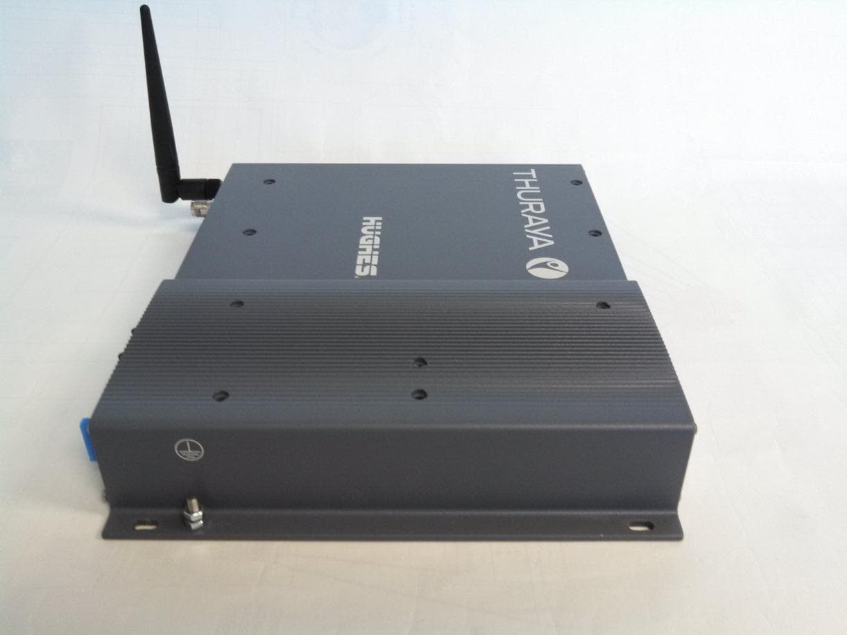
K3YHNS9105
Mar 12, 2015Thuraya IP+ Broadband Satellite IP Modem with WLAN
Equipment Class
DTS - Digital Transmission System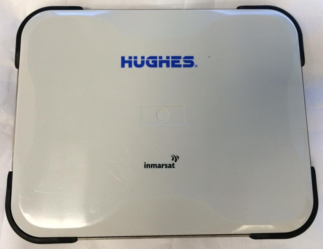
K3YHNS9211
Sep 18, 2014Satellite Terminal with WLAN functionality
Equipment Class
DTS - Digital Transmission System
K3YHNS9202
Jul 21, 2011Land Portable Terminal
Equipment Class
DTS - Digital Transmission System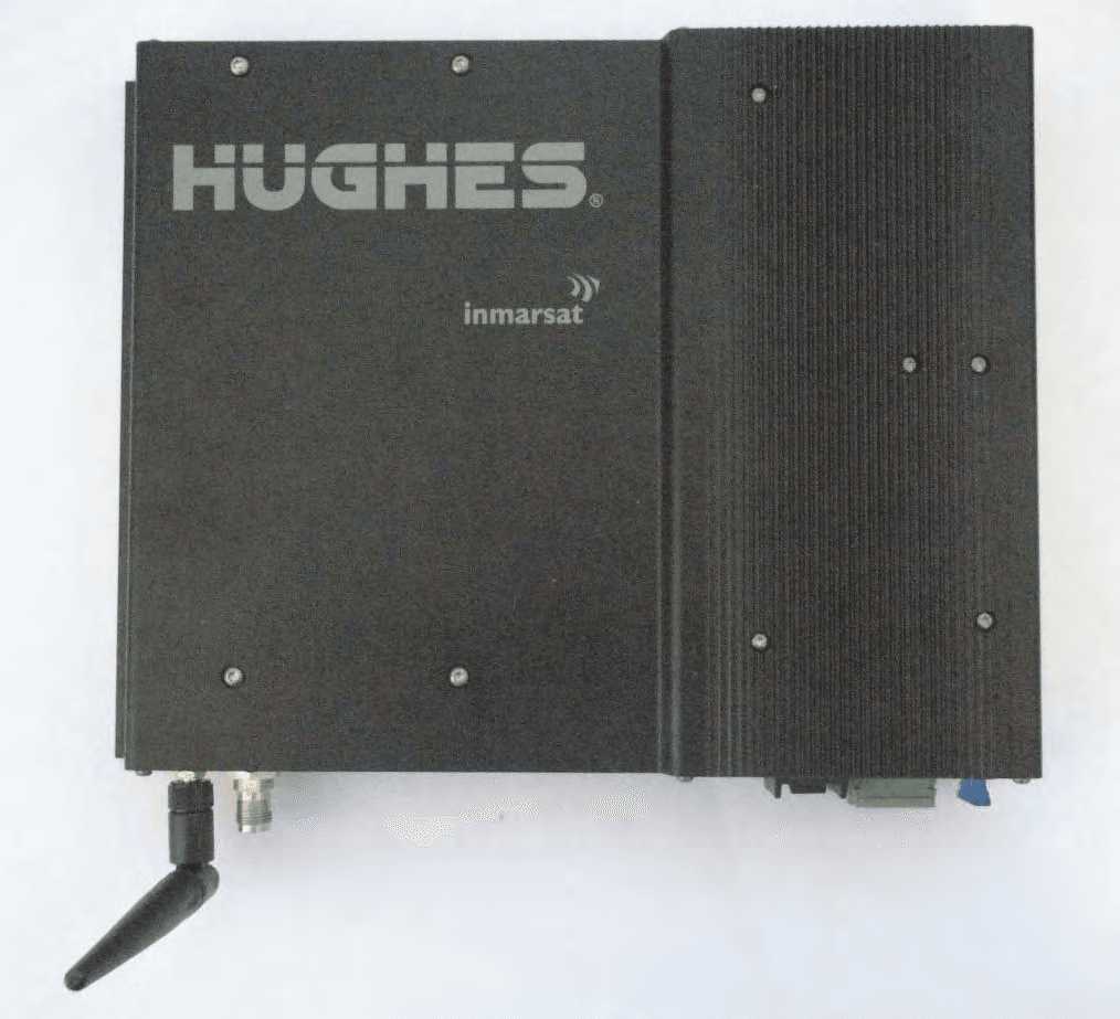
K3YHNS9450
Sep 13, 2010Land Mobile Terminal
Equipment Class
DTS - Digital Transmission System
K3YHNS9103
Jan 13, 2008Broadband Satellite IP Modem
Equipment Class
DTS - Digital Transmission System