K3YHNS9250Satellite Terminal
Hughes Network Systems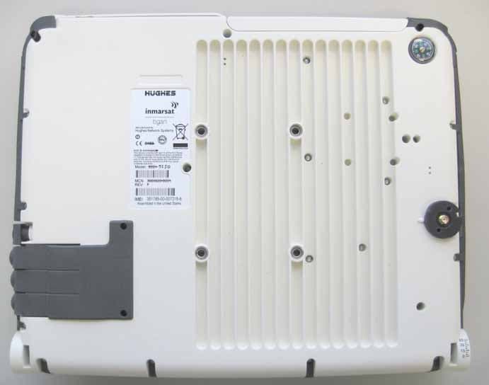
Click to zoom
Application Details
- Equipment Class
- TNB - Licensed Non-Broadcast Station Transmitter
- Date of Grant
- Apr 24, 2007
- Application Purpose
- Original Equipment
- Date of Application
- Apr 01, 2007
- Equipment Note
- Satellite Terminal
- Frequency Range
- 1626.59500000 - 1660.40500000
- Company
- Hughes Network Systems
- Country
- United States
Documents & Files
Document Text
Text extracted from the exhibit documents filed with the FCC. Open a document above to read the original.
Users Manual
Copyright © 2007 Hughes Network Systems, LLC. All rights reserved. This publication and its contents are proprietary to Hughes Network Systems, LLC. No part of this publication may be reproduced in any form or by any means without the written permission of Hughes Network Systems, LLC., 11717 Exploration Lane, Germantown, Maryland 20876. Hughes Network Systems, LLC., has made every effort to ensure the correctness and completeness of the material in this document. Hughes Network Systems, LLC., shall not be liable for errors contained herein. The information in this document is subject to change without notice. Hughes Network Systems, LLC. makes no warranty of any kind with regard to this material, including, but not limited to, the implied warranties of merchantability and fitness for a particular purpose. Trademarks All trademarks, marks, names, or product names referenced in this publication are the property of their respective owners, and Hughes Network Systems, LLC. neither endorses nor otherwise sponsors any such products or services referred to herein. HUGHES and Hughes Network Systems are trademarks of Hughes Network Systems, LLC. INMARSAT is a trademark of the International Mobile Satellite Organization. The Inmarsat LOGO and the trademark BGAN are trademarks of Inmarsat (IP) Company Limited. All trademarks are licensed to Inmarsat Limited. Hughes 9250 BGAN Terminal User's Guide 1.1 i SAFETY INFORMATION For your safety and protection, read this entire user manual before you attempt to use the Broadband Global Area Network (BGAN) Land Mobile Satellite Terminal. In particular, read this safety section carefully. Keep this safety information where you can refer to it if necessary. WARNING SYMBOLS USED IN THIS MANUAL WARNING Potential radio Frequency (RF) hazard. Where you see this alert symbol and WARNING heading, strictly follow the warning instructions to avoid injury to eyes or other personal injury. WARNING Where you see this alert symbol and WARNING heading, strictly follow the warning instructions to avoid personal injury. DANGER Electric shock hazard: Where you see this alert symbol and DANGER heading, strictly follow the warning instructions to avoid electric shock injury or death. WARNINGS FOR SATELLITE TERMINAL DO NOT STAND IN FRONT OF THE ANTENNA This device emits radio frequency energy. To avoid injury, do not place head or other body parts in front of the satellite antenna when system is operational. Maintain a distance of two meters or more from the front of the Satellite Terminal antenna. PROPERLY GROUND THE EXTERNAL ANTENNA Failure to properly ground the optional external antenna may result in severe personal injury or death. Do not attempt to ground the optional external antenna unless you have the skills to do so in accordance with local electrical codes. DO NOT OPERATE DURING ELECTRICAL STORMS Operation of the Satellite Terminal during electrical storms may result in severe personal injury or death. Disconnect the Terminal from the computer and store the unit indoors if lightning is anticipated in the area of operation. ii Hughes 9250 BGAN Terminal User's Guide 1.1 GENERAL Handle your Satellite Terminal with care. The enclosure is weather resistant per IEC 60529 IP55; however, do not submerge the unit or expose it to severe rain storms. Avoid exposing your Satellite Terminal to extreme hot or cold temperatures outside the range -25ºC to +60ºC. Avoid placing the Terminal close to cigarettes, open flames or any source of heat. Changes or modifications to the Terminal not expressly approved by Hughes Network Systems could void your authority to operate this equipment. Only use a soft damp cloth to clean the Terminal. To avoid impaired Terminal performance, please ensure the unit’s antenna is not damaged or covered with foreign material like paint or labeling. When inserting the USIM/SIM, do not bend it or damage the contacts in any way. When connecting the interface cables, do not use excessive force. IN THE VICINITY OF BLASTING WORK AND IN EXPLOSIVE ENVIRONMENTS Never use the Satellite Terminal where blasting work is in progress. Observe all restrictions and follow any regulations or rules. Areas with a potentially explosive environment are often, but not always, clearly marked. Do not use the Terminal while at a petrol filling station. Do not use near fuel or chemicals. QUALIFIED SERVICE Do not attempt to disassemble your Satellite Terminal. The unit does not contain consumer-serviceable components. Only qualified service personnel may install or repair equipment. BATTERIES AND ACCESSORIES Use approved batteries (Hughes P/N 3003702-0001) and accessories only. Use of non-approved accessories may result in loss of performance, damage to the Satellite Terminal, fire, electric shock or injury. AC mains power adapter (Hughes P/N 3003727-0001) is for indoor use only. It has an indoor operating temperature range of 0ºC to +40ºC and provides an output voltage of 20 VDC. The storage capacity of the battery decreases when operated. The terminal will only charge the battery when the temperature is within the range of 0 to 45°C. CONNECTING DEVICES Never connect incompatible devices to the Satellite Terminal. When connecting the Satellite Terminal to any other device, read the device’s User Manual for detailed safety instructions. Hughes 9250 BGAN Terminal User's Guide 1.1 iii PACEMAKERS The various brands and models of cardiac pacemakers available exhibit a wide range of immunity levels to radio signals. Therefore, people who wear a cardiac pacemaker and who want to use a Satellite Terminal should seek the advice of their cardiologist. If, as a pacemaker user, you are still concerned about interaction with the Satellite Terminal, we suggest you follow these guidelines: Maintain a distance of 30 cm between the Terminal and your pacemaker; Maintain a distance of two meters from the front of the unit’s antenna; Refer to your pacemaker product literature for information on yo…
Text truncated - open the document above for the full version.
Cover Letter(s)
1717 Exploration Lane, Germantown, MD 20876 Request for Confidentiality American Telecommunications Certification Body, Inc. 6731 Whittier Avenue Suite C110 McLean, VA 22101 To Whom It May Concern: RE: Certification Application FCC ID: K3YHNS9250 Please be advised that under the provision of 47 CFR 0.459 the following exhibits are to be held confidential on behalf of Hughes Network Systems: • Schematics • Operational Description • Block Diagram • Parts List • Tune up Procedure The application contains technical information that Hughes Network Systems deems to be trade secrets and proprietary. If made public, the information might be used to the disadvantage of the applicant in the market place. Thank you for your attention to this matter. John Rymkiewicz Regulatory Manager 301-428-5889
Cover Letter(s)
1717 Exploration Lane, Germantown, MD 20876 Letter Of Agency American Telecommunications Certification Body, Inc. 6731 Whittier Avenue Suite C110 McLean, VA 22101 To Whom It May Concern: Please be advised that Hughes Network Systems authorizes Washington Laboratories, Ltd. to act on our behalf, until otherwise notified, for applications submitted to American Telecommunications Certification Body, Inc. (ATCB). We certify that we are not subject to denial of federal benefits, which includes FCC benefits, pursuant to Section 5301 of the Anti-Drug Abuse ACT of 1988, U.S.C. 862. Further, no party, as defined in 47 CFR 1.2002(b), to the application is subject to denial of federal benefits, that includes FCC benefits. Thank you for your attention to this matter. John Rymkiewicz Regulatory Manager 301-428-5889
Cover Letter(s)
American Telecommunications Certification Body Inc. 6731 Whittier Ave, McLean, VA 22101 March 22, 2007 RE: FCC ID: K3YHNS9250_ATCB004658 Attention: Brian J. Dettling I have a few comments on this Application. Please note that further comments may arise in response to answers provided to the questions below. 1. Please note that rated power cannot be listed on part 15 grants. Actual measured power must be listed. Please note that the 731 lists the manufacturers rated power for the device. Please correct this to show the actual measured values found in the Part 15C report (i.e. 0.235W). 2. Please note that the manual states a minimum 20cm separation for the device. This does not seem appropriate as the output power of the device consists of 2 transmitters, one an 802.11 device and one a part 25 device. The part 25 device has an output power exceeding 8 watts (39.12dBm) while the WLAN has an output of 23.5mW (13.2dBm). Since this device includes a part 15 transmitter the MPE would necessarily have to include any collocation affects due to the part 25 device unless the antenna(s) are separated by more than 20cm. More than 20cm between antenna(s) would involve individual MPE assessment. Please also note that part 25 mobile rf exposure devices require measured MPE when MPE is addressed at the time of certification. As this device does not have individual site licensing but instead operates off the license of the operator, and as this device operates over 1.5GHz and 3Watts, MPE measurements are required. Please provide the MPE report showing measured MPE data. 3. Please note that I do not think a part 15 device can be partly professionally installed. The report states that when external antenna(s) are used, professional installation is required. I think that this would apply to all installations for this device in relation to part 15. Please explain/coinfirm. 4. Please note that based on the response to the above, further review may be necessary. Dennis Ward mailto:[email protected] The items indicated above must be submitted before processing can continue on the above referenced application. Failure to provide the requested information may result in application termination. Correspondence should be considered part of the permanent submission and may be viewed from the Internet after a Grant of Equipment Authorization is issued. Please do not respond to this correspondence using the email reply button. In order for your response to be processed expeditiously, you must submit your documents through the AmericanTCB.com website. Also, please note that partial responses increase processing time and should not be submitted. Any questions about the content of this correspondence should be directed to the sender.
Cover Letter(s)
Response to ATCB Comments FCC ID: K3YHNS9250 1 Washington Laboratories, Ltd. 7560 LINDBERGH DRIVE GAITHERSBURG, MD 20879 (301) 417 – 0220 FAX # (301) 417 - 9069 March 30, 2007 Mr. Dennis Ward American Telecommunications Certification Body Inc. 6731 Whittier Ave McLean, VA 22101 RE: Comments of March 22, 2007 APPLICATION: K3YHNS9250 Hughes Network Systems, Inc. Dear Mr. Ward: Below are the comments that you have provided regarding the application for certification referenced above. Our responses to those comments are in bold italic. Many responses refer you to additional exhibit(s) which has been uploaded to the application folder at the ATCB website. Thank you for your attention. Please feel free to contact us for any additional information that you may require. Regards, Steven D. Koster EMC Operations Manager Brian J. Dettling Documentation Specialist WLL Project: 9508/9514 From Dennis Ward: In addition to the comments, I also have a concern about the masks. Can you explain more on how the modulation content and the modes of operation were determined? R. All of the available modulations were tested per the Immarsat specification. All modes of operation were used. 1) Please note that rated power cannot be listed on part 15 grants. Actual measured power must be listed. Please note that the 731 lists the manufacturers rated power for the device. Please correct this to show the actual measured values found in the Part 15C report (i.e. 0.235W). R. The 731 form has been corrected. Please see “HNS9250 Application Form 731 - Pt 15 Rev 1” Response to ATCB Comments FCC ID: K3YHNS9250 2 2) Please note that the manual states a minimum 20cm separation for the device. This does not seem appropriate as the output power of the device consists of 2 transmitters, one an 802.11 device and one a part 25 device. The part 25 device has an output power exceeding 8 watts (39.12dBm) while the WLAN has an output of 23.5mW (13.2dBm). Since this device includes a part 15 transmitter the MPE would necessarily have to include any collocation affects due to the part 25 device unless the antenna(s) are separated by more than 20cm. More than 20cm between antenna(s) would involve individual MPE assessment. Please also note that part 25 mobile RF exposure devices require measured MPE when MPE is addressed at the time of certification. As this device does not have individual site licensing but instead operates off the license of the operator, and as this device operates over 1.5GHz and 3Watts, MPE measurements are required. Please provide the MPE report showing measured MPE data. R. The Part 15 antenna is integral, and the Part 25 antenna is more than 20 cm away, normally mounted on top of the vehicle it is installed in. A RF Exposure evaluation has been provided; please see “HNS9250 RF Exposure Info”. 3) Please note that I do not think a part 15 device can be partly professionally installed. The report states that when external antenna(s) are used, professional installation is required. I think that this would apply to all installations for this device in relation to part 15. Please explain/confirm. R. The professionally installed portion is the MES or Part 25 antenna. The Part 15 device has an integral antenna, thus there are no installation requirements for the Part 15 device. 4) Please note that based on the response to the above, further review may be necessary. R. Noted.
Cover Letter(s)
Hughes 9250 High Level System Block Diagram (Figure 2-1 of document “2b2b_BGAN-M_System-Design_1.0.doc”) Hughes 9201 Class 1 User Terminal Block Diagram (From BGAN Technical Specification Document) Note: Modification for the Hughes 9250 terminal (USB replaced by serial port) shown in the modification drawing, Hughes document “3500132rev1.doc” Ethernet USB GPS WLAN CPU (μP) ISDN FLASH SDRAM DSP FPGA USIM I/F Battery Power / Battery Charger Baseband to RF Interface External Power Interface RADIO Satellite Antenna TURBO DECODER RX & TX BGAN Class 1 UT TE Interfaces μP-Ethernet Interface μP-USB Interface μP-WiLAN Interface μP-GPS Interface μP-ISDN Interface DSP-ISDN Interface μP-SIM Interface Hughes 9201 User Terminal RF Architecture (From BGAN Technical Specification Document) VCTCXO 13Mhz TX IF SAW 246 MHz Pwr Det I/Q MOD PLLs I/Q DEMOD Pwr Det TX Gain TX I TX Q RX Gain RX Q RX I AFC PLL Cont RX IF SAW 188 MHz f(TX): 1626.5-1660.5 MHz f(RX): 1525.0-1559.0 MHz Internal Ant Down Converter Up Converter 376 MHz 492 MHz TX LO 1380.5-1414.5 MHz RX LO 1337-1371 MHz
External Photos
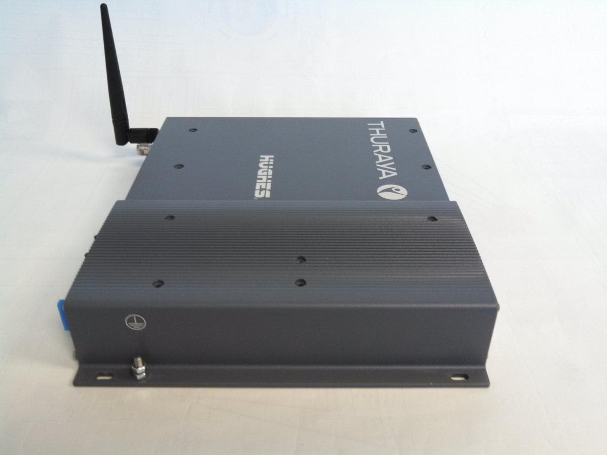
HNS9250 Photos HNS9250 Photos HNS9250 Photos HNS9250 Photos
ID Label/Location Info
HNS9250 Photos
Internal Photos
HNS9250 Photos HNS9250 Photos HNS9250 Photos HNS9250 Photos HNS9250 Photos
RF Exposure Info
Document 9508-MPE FCC ID: K3YHNS9250 RF Exposure Test Report Washington Laboratories, Ltd March, 2007 Maximum Permissible Exposure Evaluation for HUGHES NETWORK SYSTEMS HUGHES 9250 FCC ID: K3YHNS9250 March 29, 2007 WLL PROJECT #: 9508 This report may not be reproduced, except in full, without the prior written consent of Washington Laboratories, Ltd. RF Exposure Evaluation Document 9508-MPE FCC ID: K3YHNS9250 RF Exposure Test Report Washington Laboratories, Ltd March, 2007 1 Maximum Permissible Exposure Test Report for FCC ID: K3YHNS9250 1.0 Introduction This report has been prepared on behalf of Hughes Network Systems HUGHES 9250. Transmitter to show compliance with the RF exposure requirements as defined in FCC §1.1307. 1.1 Requirements Three different categories of transmitters are defined by the FCC in OET Bulletin 65. These categories are fixed installation, mobile, and portable and are defined as follows: Fixed Installations: fixed location means that the device, including its antenna, is physically secured at a permanent location and is not able to be easily moved to another location. Additionally, distance to humans from the antenna is maintained to at least 2 meters. Mobile Devices: a mobile device is defined as a transmitting device designed to be used in other than fixed locations and to be generally used in such a way that a separation distance of at least 20 centimeters is normally maintained between the transmitter's radiating structures and the body of the user or nearby persons. Transmitters designed to be used by consumers or workers that can be easily re-located, such as a wireless modem operating in a laptop computer, are considered mobile devices if they meet the 20 centimeter separation requirement. The FCC rules for evaluating mobile devices for RF compliance are found in 47 CFR §2.1091. Portable Devices: a portable device is defined as a transmitting device designed to be used so that the radiating structure(s) of the device is/are within 20 centimeters of the body of the user. Portable device requirements are found in Section 2.1093 of the FCC's Rules (47 CFR§2.1093). For this test report the Hughes Network Systems HUGHES 9250 with the SpaceComm C10 antenna for the Part 25 LMES radio and a 0dB antenna for the WLAN antenna the MPE is evaluated at the 20cm test distance. The FCC also categorizes the use of the device as based upon the user’s awareness and ability to exercise control over his or her exposure. The two categories defined are Occupational/ Controlled Exposure and General Population/Uncontrolled Exposure. These two categories are defined as follows: Document 9508-MPE FCC ID: K3YHNS9250 RF Exposure Test Report Washington Laboratories, Ltd March, 2007 2 Occupational/Controlled Exposure: In general, occupational/controlled exposure limits are applicable to situations in which persons are exposed as a consequence of their employment, who have been made fully aware of the potential for exposure and can exercise control over their exposure. This exposure category is also applicable when the exposure is of a transient nature due to incidental passage through a location where the exposure levels may be higher than the general population/uncontrolled limits, but the exposed person is fully aware of the potential for exposure and can exercise control over his or her exposure by leaving the area or by some other appropriate means. Awareness of the potential for RF exposure in a workplace or similar environment can be provided through specific training as part of a RF safety program. If appropriate, warning signs and labels can also be used to establish such awareness by providing prominent information on the risk of potential exposure and instructions on methods to minimize such exposure risks. General Population/Uncontrolled Exposure: The general population / uncontrolled exposure limits are applicable to situations in which the general public may be exposed or in which persons who are exposed as a consequence of their employment may not be made fully aware of the potential for exposure or cannot exercise control over their exposure. Members of the general public would come under this category when exposure is not employment-related; for example, in the case of a wireless transmitter that exposes persons in its vicinity. Warning labels placed on low-power consumer devices such as cellular telephones are not considered sufficient to allow the device to be considered under the occupational/controlled category, and the general population/uncontrolled exposure limits apply to these devices. Since there are no warnings or training associated with this unit and it can be used by anyone, the Hughes Network Systems HUGHES 9250 is evaluated to the General Population/Uncontrolled Exposure limits. 1.2 Radio Frequency Radiation Exposure Evaluation for the WLAN card. The highest RF output power of the unit was measured is recorded. According to §1.1310 of the FCC rules, the power density limit for General Population/Uncontrolled Exposure is 1mW/cm 2 . The MPE shall be calculated at 20cm to show compliance with the power density limit. The following formula was used to calculate the Power Density: 2 4R PG S π = Where: S = Power Density P = Output Power at the Antenna Terminals G = Gain of Transmit Antenna (linear gain-isotropic) R = Distance from Transmitting Antenna Document 9508-MPE FCC ID: K3YHNS9250 RF Exposure Test Report Washington Laboratories, Ltd March, 2007 3 Single Transmitter Frequenc y 2412MHz Limit1.000 mW/cm^2 Distance (cm), R =20cm Power (dBm), P =13.72dBm TX Ant Gain (dB), G =0dB MPE 0.00 mW/cm^2 Separation<20 cm Minimum Distance: 1.4cm 1.3 Radio Frequency Radiation Exposure Evaluation for the LMES antenna. The MPE for the LMES antenna was evaluated by testing the unit. The transmitter was turned on in a worst case mode, using a CW signal. Measurements were taken around the radome as well as 20 cm from the radom. The readings were taken with a Wandel …
Text truncated - open the document above for the full version.
Test Report
FCC Certification Test Report For the Hughes Network Systems FCC ID: K3YHNS9250 WLL REPORT# 9508-01 Rev 0 December 22, 2006 Prepared for: Hughes Network Systems 11717 Exploration Lane Germantown, MD 20876 Prepared By: Washington Laboratories, Ltd. 7560 Lindbergh Drive Gaithersburg, Maryland 20879 Hughes Network Systems BGAN-9205 FCC Certification Test Report December 2006 FCC Certification Test Report For the Hughes Network Systems FCC ID: K3YHNS9250 WLL REPORT# 9508-01 Rev 0 December 22, 2006 Prepared by: Brian J. Dettling Documentation Specialist Reviewed by: Steven D. Koster EMC Lab Operations Manager Hughes Network Systems BGAN-9205 FCC Certification Test Report December 2006 WLL Report #9508-01 - ii - © 2007 Washington Laboratories, Ltd. Abstract This report has been prepared on behalf of Hughes Network Systems HUGHES 9250 Transceiver to support the attached Application for Equipment Authorization. The test report and application are submitted for an L-Band Satellite Earth Station under Part 25 of the FCC Rules. This Certification Test Report documents the test configuration and test results for a Hughes Network Systems HUGHES 9250 Transceiver. Testing was performed on an Open Area Test Site (OATS) of Washington Laboratories, Ltd, 7560 Lindbergh Drive, Gaithersburg, MD 20879. Site description and site attenuation data have been placed on file with the FCC's Sampling and Measurements Branch at the FCC laboratory in Columbia, MD. Washington Laboratories, Ltd. has been accepted by the FCC and approved by NIST NVLAP (NVLAP Lab Code: 200066-0) as an independent FCC test laboratory. The Hughes Network Systems HUGHES 9250 Transceiver complies with the limits for an L-Band Satellite Earth Station device under FCC Part 25. Hughes Network Systems BGAN-9205 FCC Certification Test Report December 2006 WLL Report #9508-01 - iii - © 2007 Washington Laboratories, Ltd. Table of Contents Abstract ....................................................................................................................................................... ii 1 Introduction......................................................................................................................................1 1.1 Compliance Statement .................................................................................................................1 1.2 Test Scope ....................................................................................................................................1 1.3 Contract Information....................................................................................................................1 1.4 Test Dates ....................................................................................................................................1 1.5 Test and Support Personnel .........................................................................................................1 1.6 Abbreviations ...............................................................................................................................2 2 Equipment Under Test .....................................................................................................................3 2.1 Test Configuration .......................................................................................................................3 2.2 Testing Algorithm........................................................................................................................5 2.3 Test Location ...............................................................................................................................5 2.4 Measurements ..............................................................................................................................5 2.5 Measurement Uncertainty............................................................................................................5 3 Test Equipment ................................................................................................................................6 4 Test Results ......................................................................................................................................7 4.1 RF Power Output (FCC 25.204) ..................................................................................................7 4.2 Occupied Bandwidth..................................................................................................................15 4.3 Emission Limitations per FCC Part 25.202(f) ...........................................................................23 4.4 Radiated Spurious Emissions: EIRP Data (FCC §25.202(f)) ....................................................80 4.5 Radiated Spurious Emissions per FCC §25.216 ........................................................................83 4.6 Frequency Stability: (FCC Part §2.1055) ................................................................................106 List of Tables Table 1. Device Summary............................................................................................................................3 Table 2: Test Equipment List.......................................................................................................................6 Table 3: RF Power Output ...........................................................................................................................7 Table 4: Occupied Bandwidth Results.......................................................................................................15 Table 5. Radiated Emissions <1000MHz Test Data Sheet ........................................................................81 Table 6. Radiated Emissions >1000MHz Test Data Sheet ........................................................................82 Table 7: Frequency Stability Test Data .............................................................................................…
Text truncated - open the document above for the full version.
Test Report
Hughes Network Systems BGAN-9205 FCC Certification Test Report December 2006 WLL Report #9508-01 - Page 23 of 107 - © 2007 Washington Laboratories, Ltd. 4.3 Emission Limitations per FCC Part 25.202(f) Radiated spurious emissions must comply with the requirements of §25.202 (f) of FCC. The limits for the spurious emissions for FCC Part 25 are as follows: FCC Part 25.202(f): Spurious emissions must comply with the requirements of §25.202(f). The limits for the spurious emissions are as follows: The mean power of emissions shall be attenuated below the mean output power of the transmitter in accordance with the following schedule: (1) In any 4 kHz band, the center frequency of which is removed from the assigned frequency by more than 50 percent up to and including 100 percent of the authorized bandwidth: 25 dB; (2) In any 4 kHz band, the center frequency of which is removed from the assigned frequency by more than 100 percent up to and including 250 percent of the authorized bandwidth: 35 dB; (3) In any 4 kHz band, the center frequency of which is removed from the assigned frequency by more than 250 percent of the authorized bandwidth: An amount equal to 43 dB plus 10 times the logarithm (to the base 10) of the transmitter power in watts. 4.3.1 Test Procedure For the FCC Part 25 requirements the unit was set to transmit at 1643MHz and the emissions were measured to +/-250% of the authorized bandwidth and compared to the emission mask specified in FCC Part 25.202(f). The authorized bandwidth used in the calculations for the limit was 10kHz. 4.3.2 Test Results The EUT complies with the emissions mask requirements FCC Part 25.202(f). The following plots provide the test results for the modulation modes. Hughes Network Systems BGAN-9205 FCC Certification Test Report December 2006 WLL Report #9508-01 - Page 24 of 107 - © 2007 Washington Laboratories, Ltd. Figure 15: FCC Part 25 QAM 1 Emission Mask Hughes Network Systems BGAN-9205 FCC Certification Test Report December 2006 WLL Report #9508-01 - Page 25 of 107 - © 2007 Washington Laboratories, Ltd. Figure 16: FCC Part 25 Conducted Spurious Emissions Data, QAM 1 30MHz - 1000MHz Hughes Network Systems BGAN-9205 FCC Certification Test Report December 2006 WLL Report #9508-01 - Page 26 of 107 - © 2007 Washington Laboratories, Ltd. Figure 17: FCC Part 25 Conducted Spurious Emissions Data, QAM 1 1000 – 1500MHz Hughes Network Systems BGAN-9205 FCC Certification Test Report December 2006 WLL Report #9508-01 - Page 27 of 107 - © 2007 Washington Laboratories, Ltd. Figure 18: FCC Part 25 Conducted Spurious Emissions Data, QAM 1 1500 – 1643MHz Hughes Network Systems BGAN-9205 FCC Certification Test Report December 2006 WLL Report #9508-01 - Page 28 of 107 - © 2007 Washington Laboratories, Ltd. Figure 19: FCC Part 25 Conducted Spurious Emissions Data, QAM 1 1643MHz – 2GHz Hughes Network Systems BGAN-9205 FCC Certification Test Report December 2006 WLL Report #9508-01 - Page 29 of 107 - © 2007 Washington Laboratories, Ltd. Figure 20: F…
Text truncated - open the document above for the full version.
Contact Information
Applicant
Norbert Owona(Sr. Member Technical Staff)
Technical Specifications
| # | Rule Parts | Frequency Range | Power Output | Emission | Tolerance |
|---|---|---|---|---|---|
| 1 | 25 | 1.63 GHz - 1.66 GHz | 8.2 W | 184KD7W | 0.0001000000 ppm |
Other Applications from Hughes Network Systems
K3YHNS9105
Mar 12, 2015Thuraya IP+ Broadband Satellite IP Modem with WLAN
Equipment Class
DTS - Digital Transmission System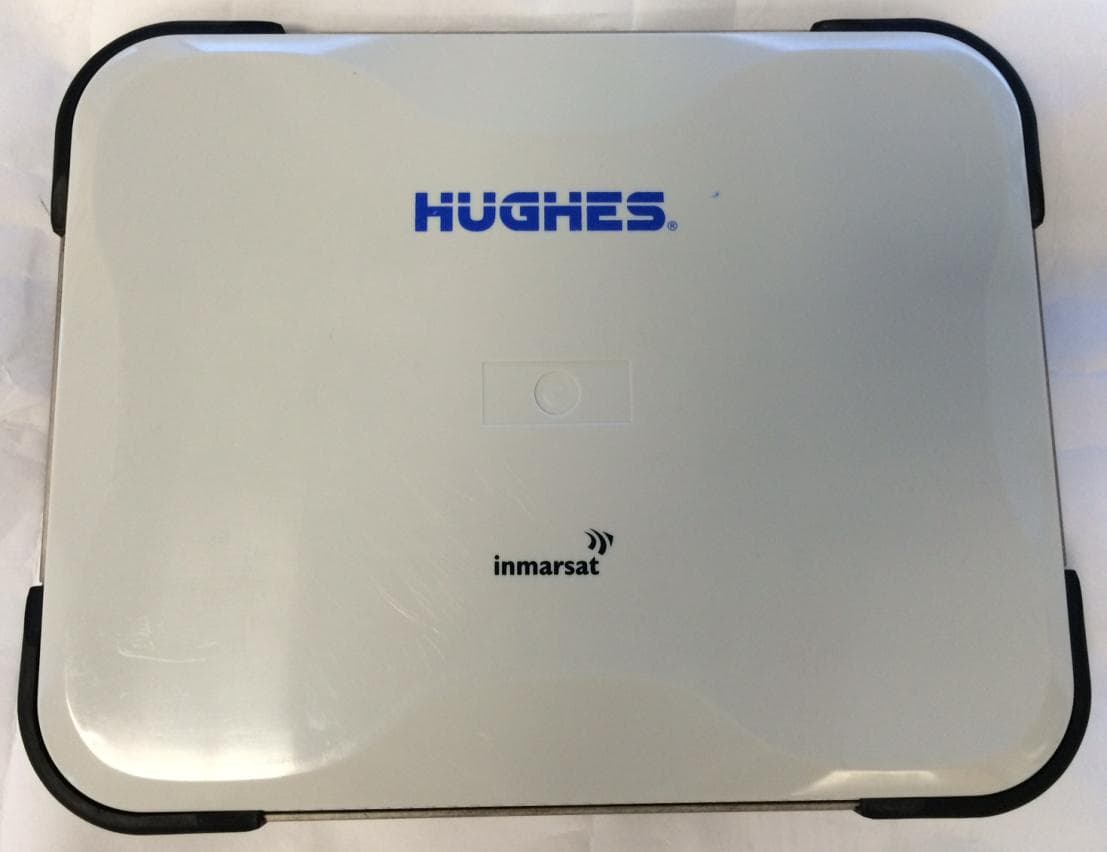
K3YHNS9211
Sep 18, 2014Satellite Terminal with WLAN functionality
Equipment Class
DTS - Digital Transmission System
K3YHNS9202
Jul 21, 2011Land Portable Terminal
Equipment Class
DTS - Digital Transmission System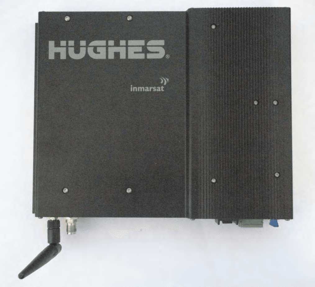
K3YHNS9450
Sep 13, 2010Land Mobile Terminal
Equipment Class
DTS - Digital Transmission System
K3YHNS9103
Jan 13, 2008Broadband Satellite IP Modem
Equipment Class
DTS - Digital Transmission System