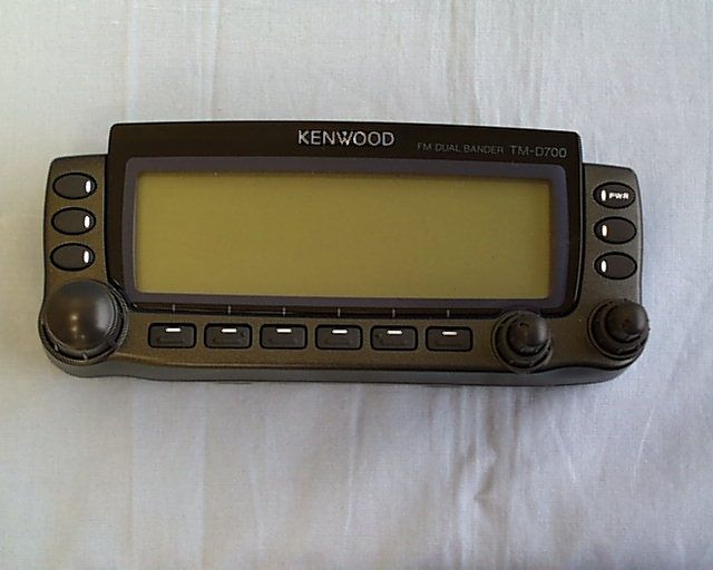
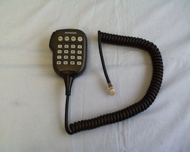
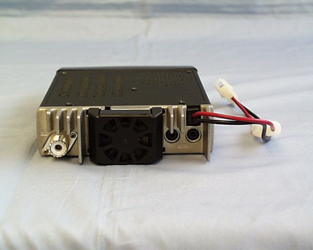
K4428451110144/440MHz FM Dual Bander
JVC KENWOOD Corporation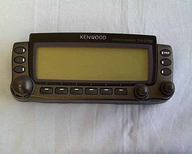
Click to zoom
Application Details
- Equipment Class
- CSR - Scanning Receiver
- Date of Grant
- Dec 09, 1999
- Application Purpose
- Original Equipment
- Date of Application
- Sep 16, 1999
- Equipment Note
- 144/440MHz FM Dual Bander
- Frequency Range
- 894.00000000 - 960.00000000
- Company
- JVC KENWOOD Corporation
- Country
- Japan
Documents & Files
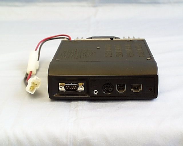
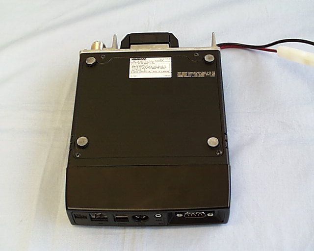
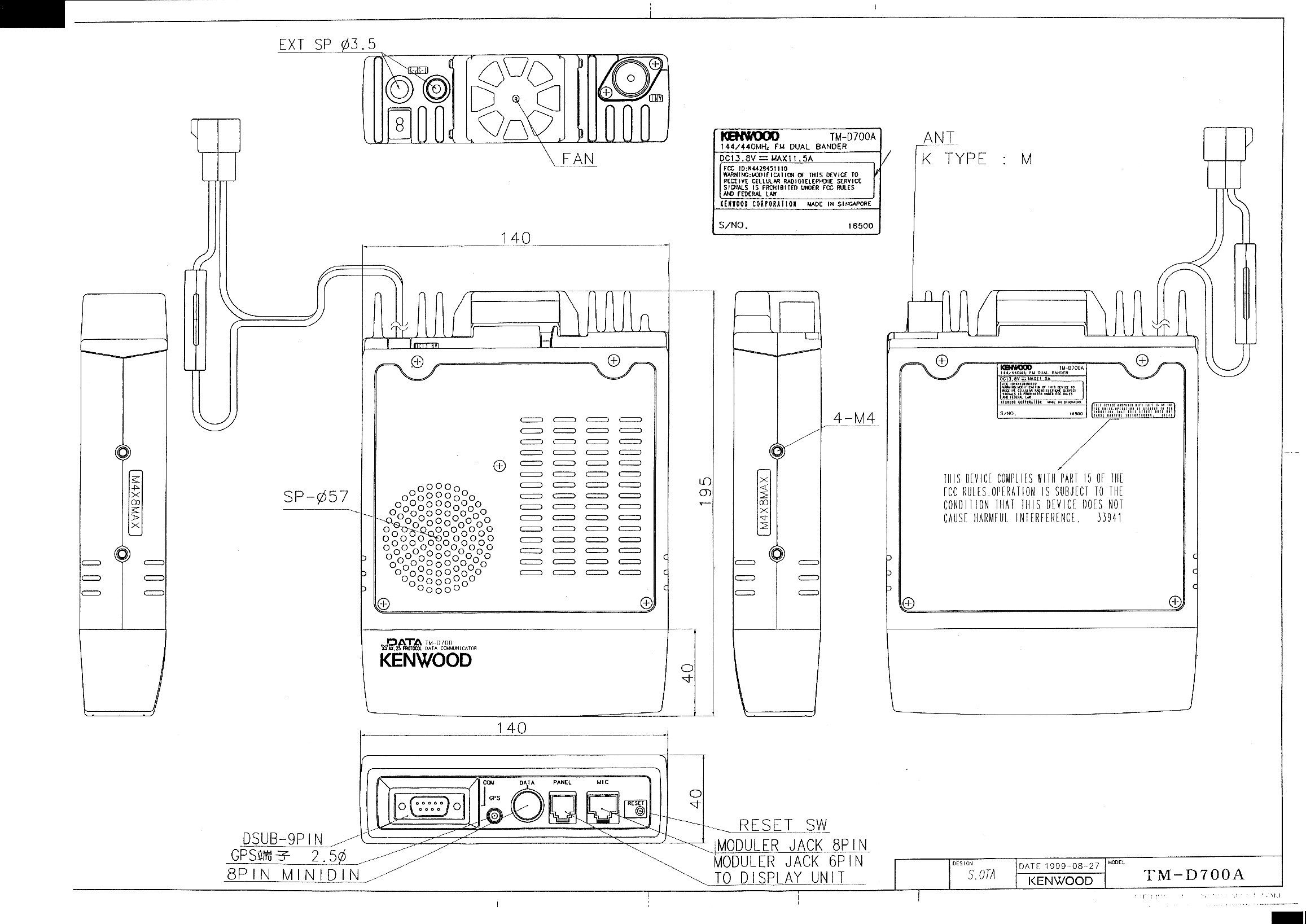
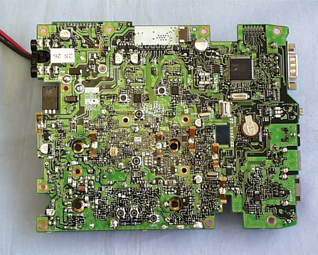
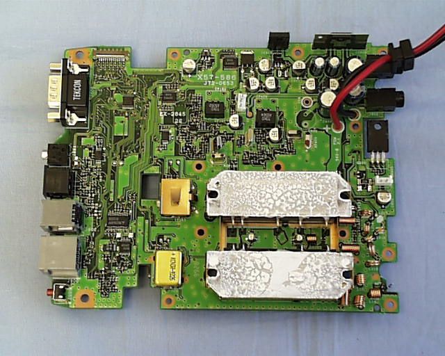
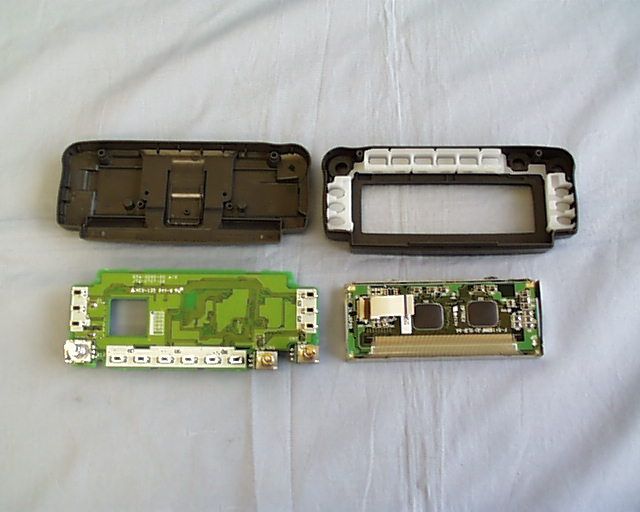
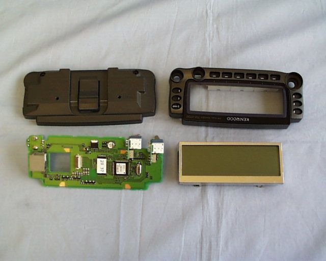
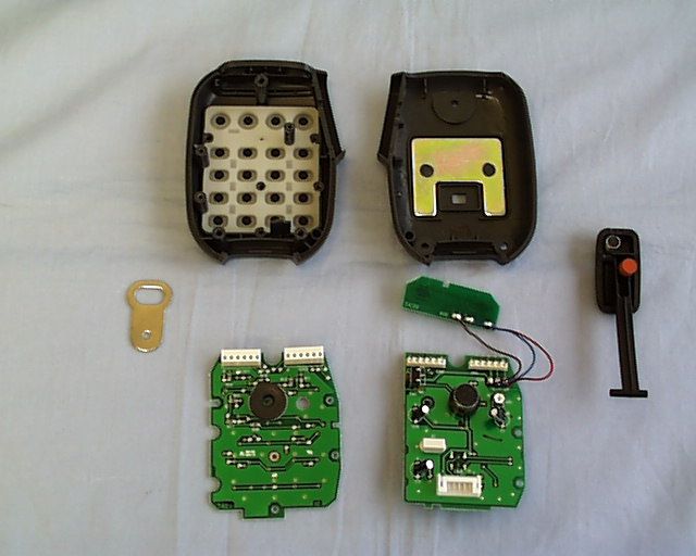
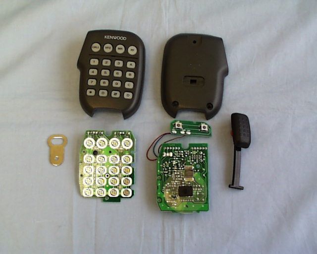
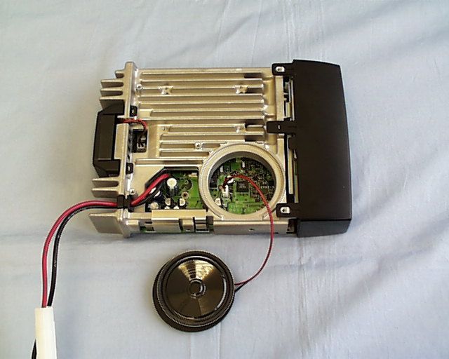
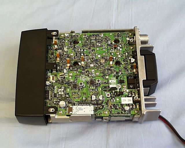
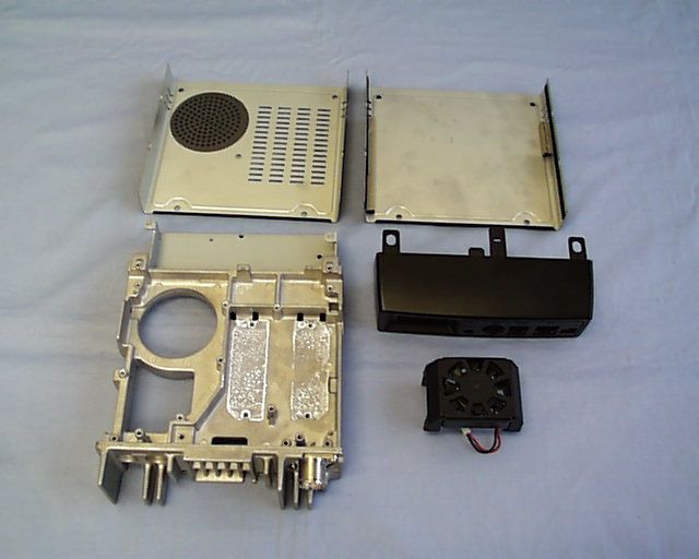
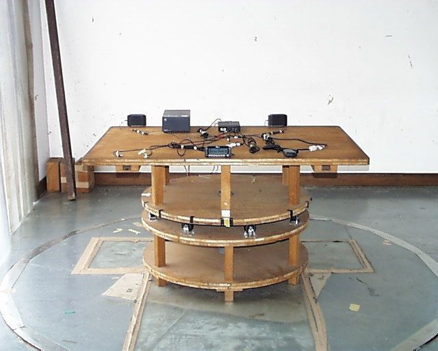
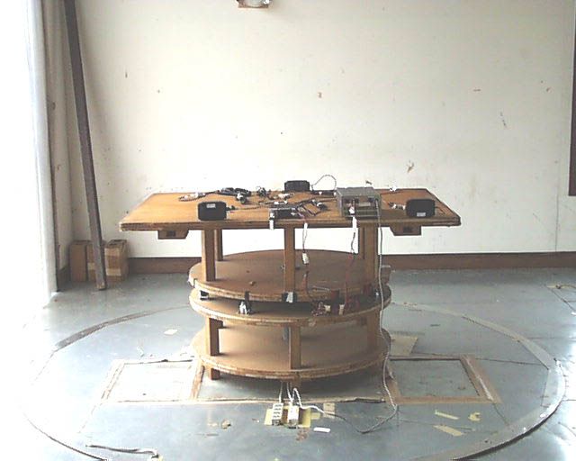
Document Text
Text extracted from the exhibit documents filed with the FCC. Open a document above to read the original.
Users Manual
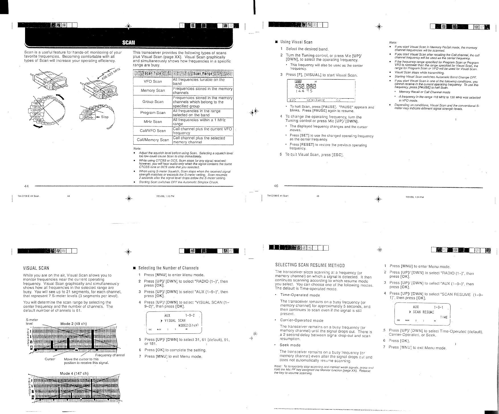
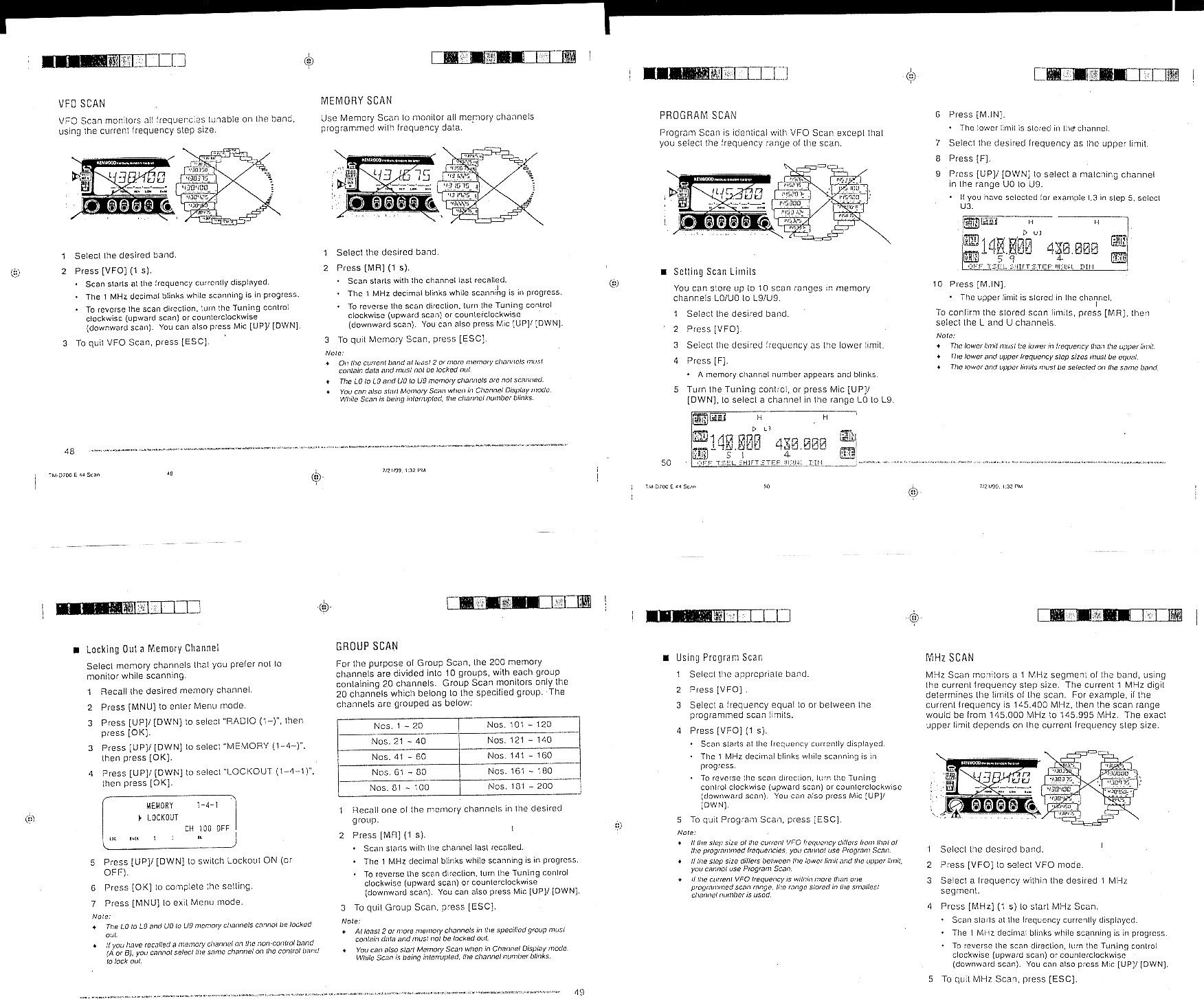
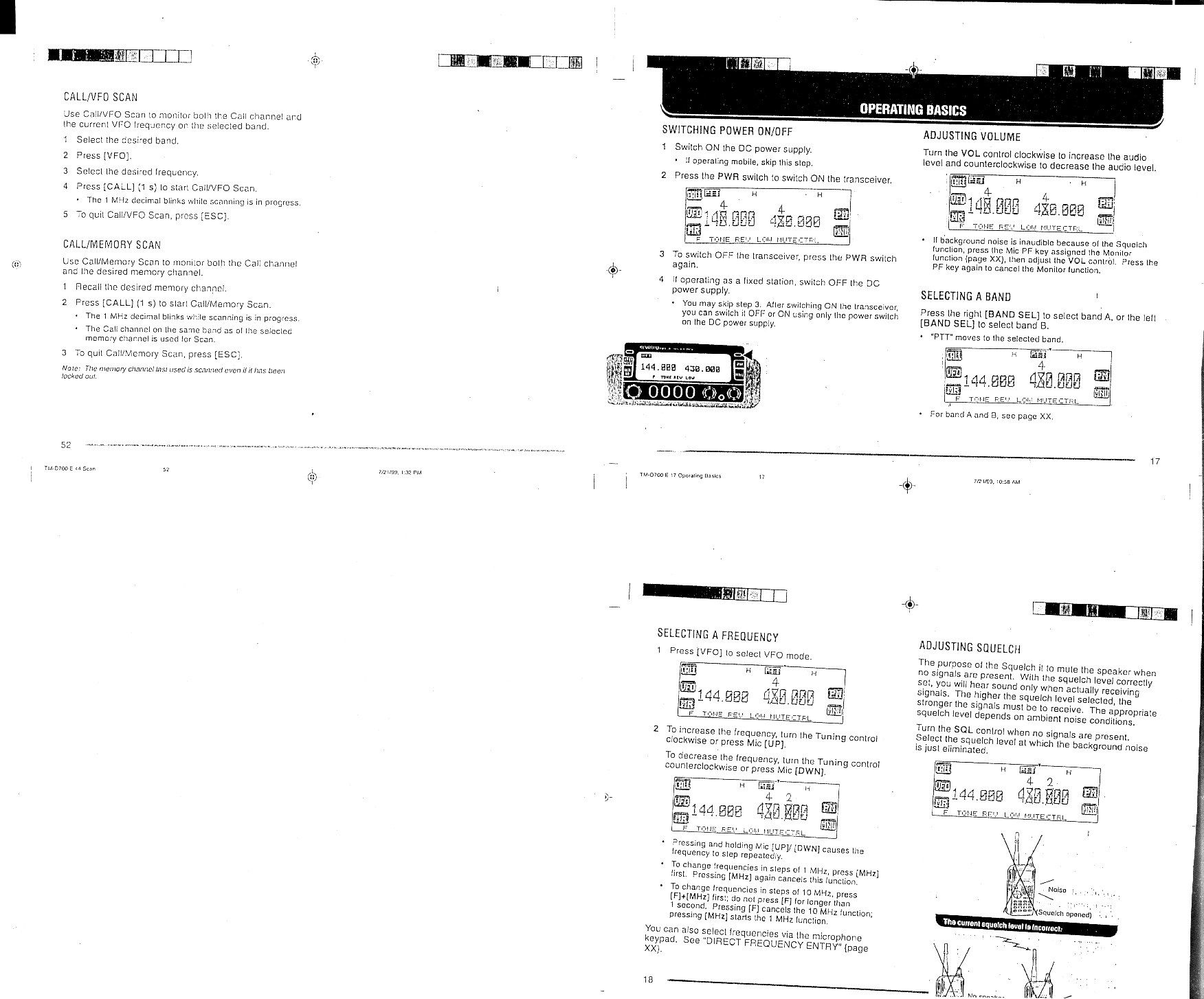
THANK YOU! We are grateful you decided to purchase this KENWOOD FM transceiver. KENWOOD always provides Amateur Radio products which surprise and excite serious hobbyists. This transceiver is no exception. This time KENWOOD presents a mobile with a built-in TNC to make data communications much more convenient than before. KENWOOD believes that this product will satisfy your requests on both voice and data communications. MODELS COVERED BY THIS MANUAL The models listed below are covered by this manual. TM-D700A:144/440 MHz FM Dual Bander (U.S.A./ Canada) TM-D700E:144/430 MHz FM Dual Bander (Europe) TM-D700A:144/430 MHz FM Dual Bander (General market) FEATURES i PRECAUTIONS Please observe the following precautions to prevent fire, personal injury, and transceiver damage: • When operating mobile, do not attempt to configure your transceiver while driving because it is simply too dangerous. • Be aware of local laws pertaining to the use of headphones/headsets while driving on public roads. If in doubt, do not wear headphones while mobiling. • Do not transmit with high output power for extended periods. The transceiver may overheat. • Do not modify this transceiver unless instructed by this manual or by KENWOOD documentation. • Do not expose the transceiver to long periods of direct sunlight nor place the transceiver close to heating appliances. • Do not place the transceiver in excessively dusty areas, humid areas, wet areas, nor on unstable surfaces. • If an abnormal odor or smoke is detected coming from the transceiver, turn OFF the power immediately. Contact a KENWOOD service station or your dealer. • The transceiver is designed for a 13.8 V power source. Never use a 24 V battery to power the transceiver. NOTICES TO THE USER One or more of the following statements may be applicable: FCC WARNING This equipment generates or uses radio frequency energy. Changes or modifications to this equipment may cause harmful interference unless the modifications are expressly approved in the instruction manual. The user could lose the authority to operate this equipment if an unauthorized change or modification is made. INFORMATION TO THE DIGITAL DEVICE USER REQUIRED BY THE FCC This equipment has been tested and found to comply with the limits for a Class B digital device, pursuant to Part 15 of the FCC Rules. These limits are designed to provide reasonable protection against harmful interference in a residential installation. This equipment generates, uses and can generate radio frequency energy and, if not installed and used in accordance with the instructions, may cause harmful interference to radio communications. However, there is no guarantee that the interference will not occur in a particular installation. If this equipment does cause harmful interference to radio or television reception, which can be determined by turning the equipment off and on, the user is encouraged to try to correct the interference by one or more of the following measures: •Reorient or relocate the receiving antenna. •Increase the separation between the equipment and receiver. •Connect the equipment to an outlet on a circuit different from that to which the receiver is connected. •Consult the dealer for technical assistance. When condensation occurs inside the transceiver: Condensation possibly occurs inside the transceiver in such a case where the room is warmed using a heater on cold days or where the transceiver is quickly moved from a cold room to a warm room. When condensation occurs, the microcomputer and/or the transmit/receive circuits may become unstable, resulting in transceiver malfunction. If this happens, turn OFF the transceiver and just wait for a while. When the condensed droplets disappear, the transceiver will function normally. 1 SUPPLIED ACCESSORIES A market code (K, E, or M4) can be found on the label attached on the package box. 1 The screw set includes screws for attaching the microphone hanger {page XX}. 2 When using the transceiver as a fixed station, you may put these cushions under the main unit to prevent it from scratching the desktop. CONVENTIONS FOLLOWED IN THIS MANUAL The writing conventions described below have been followed to simplify instructions and avoid unnecessary repetition. noitcurtsnIodottahW sserP]YEK[.esaelerdnasserPYEK. sserP )s1(]YEK[. dlohdnasserPYEKrodnoces1rof .regnol sserP]1YEK[, ]2YEK[. sserP1YEKesaeler,yliratnemom 1YEKsserpneht,2YEK. sserP+]YEK[ NOREWOP. sserp,FFOrewopreviecsnarthtiW dlohdnaYEKehtNOnrutneht, gnisserpybrewopreviecsnart ]RWP[. sserP)s1(]F[, ]YEK[. dlohdnasserP]F[rodnoces1rof sserpneht,regnolYEK. sserP]F[,]YEK[ )s1(. sserP]F[esaeler,yliratnemom]F[, dlohdnasserpnehtYEK1rof .regnolrodnoces sserP]YEK[+]F[.dlohdnasserP]F[sserpneht,YEK. yrosseccArebmuNtraPytitnauQ enohporciM MD35-CM:K 54-CM:4M/E XX-6850-19T XX-6930-19T 1 1 elbacrewopCDXX-1112-03E1 )A51(esufreviecsnarTXX-7100-15F1 tekcarbgnitnuomlenaptnorF )riapeno( XX-3660-92J XX-4660-92J 1 1 tekcarbgnitnuomtinu-niaMXX-8260-92J1 regnahenohporciM )ylnoK( XX-6251-91J1 tinuniamrofteswercS K 1 4M/E XX-2830-99N XX-1330-99N 1 1 lenaptnorfrofteswercSXX-4102-99N1 elbacgulpraludoMXX-1933-03E1 noihsuC 2 XX-8840-20J4 dracytnarraW )ylnoeporuE/adanaC/.A.S.U( —1 launamnoitcurtsnI niaM snoitacinummoCdezilaicepS XX-8221-26B XXXXXX-26B 1 1 2 nInstallation Steps PREPARATION MOBILE INSTALLATION This transceiver asks you to install the front panel and main unit at separate positions. Select safe, convenient locations inside your vehicle that minimize danger to your passengers and yourself while the vehicle is in motion. For example, consider installing the front panel under the dash in front of the passenger seat so that knees or legs will not strike the panel during sudden braking of your vehicle. Try to pick well-ventilated locations that are shielded from direct sunlight. Note: Unlike the previous KENWOOD mobile transceivers, this transceiver does not allow the front panel and main unit to be joined. nInstallation Example MODUL…
Text truncated - open the document above for the full version.
Attestation Statements
FCC RULES REGARDING CELLULAR: §2.1033 Application for certification. (b) Applications for equipment operating under Parts 11, 15 and 18 of the rules shall be accompanied by a technical report containing the following information: (11) Applications for the certification of scanning receivers shall include a statement describing the methods used to comply with the design requirements of all parts of §15.121 of this chapter. The application must specifically include a statement assessing the vulnerability of the equipment to possible modification and describing the design features that prevent the modification of the equipment by the user to receive transmissions from the Cellular Radiotelephone Service. The application must also demonstrate compliance with the signal rejection requirement of §15.121 of this chapter, including details on the measurement procedures used to demonstrate compliance. §15.121 Scanning receivers and frequency converters used with scanning receivers. (a) Except as provided in paragraph (c) of this section, scanning receivers and frequency converters designed or marketed for use with scanning receivers, shall: (1) Be incapable of operating (tuning), or readily being altered by the user to operate, within the frequency bands allocated to the Cellular Radiotelephone Service in Part 22 of this chapter (cellular telephone bands). Scanning receivers capable of “readily being altered by the user” include, but are not limited to, those for which the ability to receive transmissions in the cellular telephone bands can be added by clipping the leads of, or installing, a simple component such as a diode, resistor or jumper wire; replacing a plug-in semiconductor chip; or programming a semiconductor chip using special access codes or an external device, such as a personal computer. Scanning receivers, and frequency converters designed for use with scanning receivers, also shall be incapable of converting digital cellular communication transmissions to analog voice audio. (2) Be designed so that the tuning, control and filtering circuitry is inaccessible. The design must be such that any attempts to modify the equipment to receive transmissions from the Cellular Radiotelephone Service likely will render the receiver inoperable. (b) Except as provided in paragraph (c) of this section, scanning receivers shall reject any signals from the Cellular Radiotelephone Service frequency bands that are 38 dB or higher based upon a 12 dB SINAD measurement, which is considered the threshold where a signal can be clearly discerned from any interference that may be present. (c) Scanning receivers and frequency converters designed or marketed for use with scanning receivers, are not subject to the requirements of paragraphs (a) and (b) of this section provided that they are manufactured exclusively for, and marketed exclusively to, entities described in 18 USC 2512(2), or are marketed exclusively as test equipment pursuant to §15.3(dd). (d) Modification of a scanning receiver to receive transmissions from Cellular Radiotelephone Service frequency bands will be considered to constitute manufacture of such equipment. This includes any individual, individuals, entity or organization that modifies one or more scanners. Any modification to a scanning receiver to receive transmissions from the Cellular Radiotelephone Service frequency bands voids the certification of the scanning receiver, regardless of the date of manufacture of the original unit. In addition, the provisions of §15.23 shall not be interpreted as permitting modification of a scanning receiver to receiver Cellular Radiotelephone Service transmissions. (e) Scanning receivers and frequency converters designed for use with scanning receivers shall not be assembled from kits or marketed in kit form unless they comply with the requirements in paragraph (a) through (c) of this section. (f)(1) Scanning receivers shall have a label permanently affixed to the product, and this label shall be readily visible to the purchaser at the time of purchase. The label shall read as follows: WARNING: MODIFICATION OF THIS DEVICE TO RECEIVE CELLULAR RADIOTELEPHONE SERVICE SIGNALS IS PROHIBITED UNDER FCC RULES AND FEDERAL LAW. (2) “Permanently affixed” means that the label is etched, engraved, stamped, silkscreened, indelibly printed or otherwise permanently marked on a permanently attached part of the equipment or on a nameplate of metal plastic or other material fastened to the equipment by welding, riveting, or permanent adhesive. The label shall be designed to last the expected lifetime of the equipment in the environment in which the equipment may be operated and must not be readily detachable. The label shall not be a stick-on, paper label. REQUIRED STATEMENTS: §15.121 Scanning receivers and frequency converters used with scanning receivers. This device is incapable of operating (tuning), or readily being altered by the user to operate, within the frequency bands allocated to the Cellular Radiotelephone Service in Part 22 (cellular telephone bands). This scanning receiver is incapable of “readily being altered by the user” including, but not limited to, the ability to receive transmissions in the cellular telephone bands, which cannot be added by clipping the leads of, or installing, a simple component such as a diode, resistor or jumper wire; replacing a plug-in semiconductor chip; or programming a semiconductor chip using special access codes or an external device, such as a personal computer. Furthermore, this scanning receiver is incapable of converting digital cellular communication transmissions to analog voice audio. By design, the tuning, control and filtering circuitry is inaccessible, for these reasons: 1. The PLL Control CPU can not select or adjust between 824.0000MHz to 848.9999MHz, and 869.0000MHz to 893.9999MHz. 2. The CPU employed has internal flash memory, however the programming information cannot be read out from the CPU, therefore…
Text truncated - open the document above for the full version.
Attestation Statements
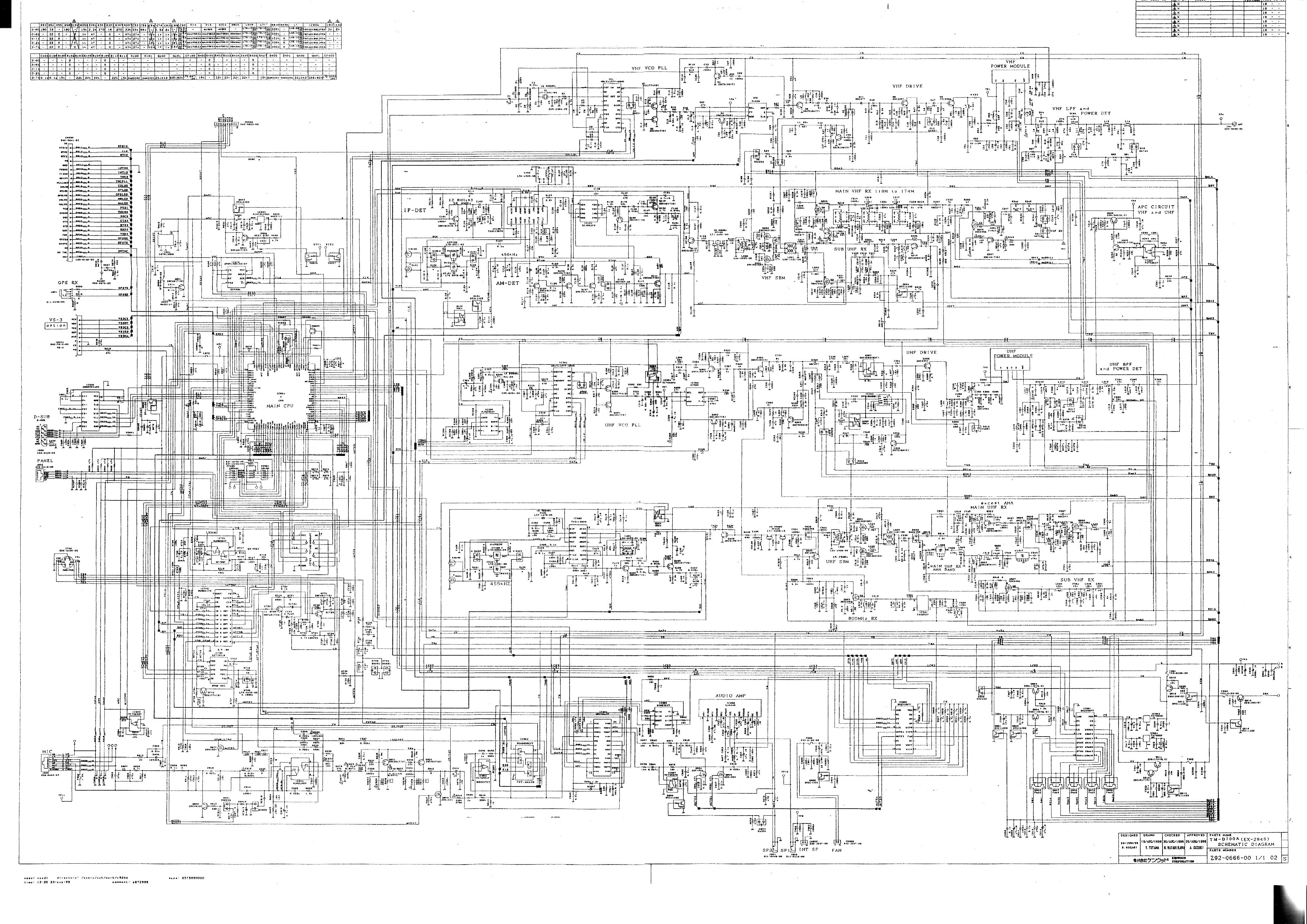
TM-D700A has function of receiving 800MHz-band. However, it cannot receive Cellular band because the CPU is programmed not to synchronize frequency band 824-849MHz and 869-894MHz. For example, in case that it increases the frequency from 823MHz at 5kHz step, it normally becomes 824.000MHz after 823.995MHz, but CPU controls it to become 849.000MHz. Opposite is as same, in case that it decreases the frequency from 849.000MHz, it normally becomes 843.995MHz, but CPU controls it to become 823.995MHz. CPU of this receiver cannot read program nor make or write program without special developed unit. Therefore, user cannot tamper with CPU. As for Image receiving, to avoid receiving Cellular band caused with upper heterodyne and lower heterodyne, CPU modifies the construction of frequency. Examples, when it receives 960.100MHz in lower heterodyne, Intermediate Frequency is 45.05MHz and local oscillation frequency is 915.05MHz. Then, 870.000MHz, which is upper heterodyne against 45.05MHz, can be received. In this case, not to receive Cellular band 870.000MHz frequency, it uses local oscillation frequency of upper heterodyne 1005.15MHz. By changing construction of the frequency like this, Image receiving frequency cannot get into the Cellular band. However, 914-934MHz bands cannot avoid Cellular band with changing the frequency construction, therefore, it takes the method of the CPU program above mentioned for this band. Even if a user try to modify, it is impossible for user to tamper with CPU. Because of above-mentioned reason, this device is compliance to Section 15.121.
Block Diagram
K 438.000 449.995M Hz K 144.000 147.995M Hz K 392.950 404.945M Hz K 182.850 186.845M Hz E 430.000 439.995M Hz E 144.000 145.995M Hz E 384.950 394.945M Hz E 182.850 184.845M Hz A M 430.000 439.995M Hz D M 144.000 145.995M Hz G M 384.950 394.945M Hz J M 182.850 184.845M Hz K 438.000 439.995M Hz K 144.000 147.995M Hz K 378.100 386.090M Hz K 199.575 205.5725 MHz E 430.000 439.995M Hz E 144.000 145.995M Hz E 378.100 382.090M Hz E 195.575 200.5725 MHz B M 430.000 439.995M Hz E M 144.000 145.995M Hz H M 378.100 382.090M Hz K M 195.575 200.5725 MHz K 144.000 147.995M Hz K 438.000 449.995M Hz K 189.050 193.045M Hz K 399.150 411.145M Hz E 144.000 145.995M Hz E 430.000 439.995M Hz E 189.050 191.045M Hz E 391.150 401.145M Hz C M 144.000 145.995M Hz F M 430.000 439.995M Hz I M 189.050 191.045M Hz L M 391.150 401.145M Hz UHF TX AF AMP Crystal12.8MHz MIC TM-D700A/E Frequency H MAIN UHF RX SUB VHF RX VHF TX MAIN VHF RX SUB UHF RX IF 2 DET VCO 1VCO 2 A G 1/2 I D J ×2 K L PLL 1PLL 2 OSC IF 1 DET Crystal 45.505MHz ×3 MIC AMP IF 45.05MHz IF 38.85MHz 2nd IF450kHz2nd IF455kHz AF AF SP TNC 12.8MH B F E C 38.4MH OSC Crystal12.8MHz
Cover Letter(s)
ZACTA TECHNOLOGY CORPORATION September 16, 1999 Yonezawa Testing Center 4149-7 Hachimanpara 5-Chome Yonezawa-shi Yamagata 992-1128 Japan Phone: +81-238-28-2880 Fax: +81-238-28-2888 ATTN: FEDERAL COMMUNICATIONS COMMISSION Equipment Authorization Division 7435 Oakland Mills Road Columbia, MD 21046 USA RE: FCC Part 15 Certification [Scanning Receiver / FCC ID: K4428451110] CSR-Scanning Receiver File #:Z02C-99246 Applicant: Kenwood Corporation Gentlemen: Please find attached exhibits listed below; Attestation Statements Block Diagram External Photos ID Label / Location info. Internal Photos Operational Description Schematics Test Report Test Setup Photos User Manual The EUT; scanning receiver is a composite device and another certification filing as PC peripheral has been filed simultaneously. Your prompt attention to this matter would be highly appreciated. If there are any questions or if further information is needed, please contact our USA point of contact as follows: Zacta International Corporation 21220 Devonshire street, Suite 201 Chatsworth CA. 91311 Contact Name: Yoshi Namiki / Consultant Phone: 818-727-1740 Fax: 818-727-7938 E-mail: [email protected] We also hereby certify that no party to this application is subject to denial of benefits, including FCC benefits, pursuant to section 5301 of Anti-Drug Act of 1988, 21 U.S.C.853(a). Sincerely yours, Akemi Suzuki [email protected] Filing Coordinator of ZACTA TECHNOLOGY CORPORATION
Operational Description
FCC RULES REGARDING CELLULAR: §2.1033 Application for certification. (b) Applications for equipment operating under Parts 11, 15 and 18 of the rules shall be accompanied by a technical report containing the following information: (11) Applications for the certification of scanning receivers shall include a statement describing the methods used to comply with the design requirements of all parts of §15.121 of this chapter. The application must specifically include a statement assessing the vulnerability of the equipment to possible modification and describing the design features that prevent the modification of the equipment by the user to receive transmissions from the Cellular Radiotelephone Service. The application must also demonstrate compliance with the signal rejection requirement of §15.121 of this chapter, including details on the measurement procedures used to demonstrate compliance. §15.121 Scanning receivers and frequency converters used with scanning receivers. (a) Except as provided in paragraph (c) of this section, scanning receivers and frequency converters designed or marketed for use with scanning receivers, shall: (1) Be incapable of operating (tuning), or readily being altered by the user to operate, within the frequency bands allocated to the Cellular Radiotelephone Service in Part 22 of this chapter (cellular telephone bands). Scanning receivers capable of “readily being altered by the user” include, but are not limited to, those for which the ability to receive transmissions in the cellular telephone bands can be added by clipping the leads of, or installing, a simple component such as a diode, resistor or jumper wire; replacing a plug-in semiconductor chip; or programming a semiconductor chip using special access codes or an external device, such as a personal computer. Scanning receivers, and frequency converters designed for use with scanning receivers, also shall be incapable of converting digital cellular communication transmissions to analog voice audio. (2) Be designed so that the tuning, control and filtering circuitry is inaccessible. The design must be such that any attempts to modify the equipment to receive transmissions from the Cellular Radiotelephone Service likely will render the receiver inoperable. (b) Except as provided in paragraph (c) of this section, scanning receivers shall reject any signals from the Cellular Radiotelephone Service frequency bands that are 38 dB or higher based upon a 12 dB SINAD measurement, which is considered the threshold where a signal can be clearly discerned from any interference that may be present. (c) Scanning receivers and frequency converters designed or marketed for use with scanning receivers, are not subject to the requirements of paragraphs (a) and (b) of this section provided that they are manufactured exclusively for, and marketed exclusively to, entities described in 18 USC 2512(2), or are marketed exclusively as test equipment pursuant to §15.3(dd). (d) Modification of a scanning receiver to receive transmissions from Cellular Radiotelephone Service frequency bands will be considered to constitute manufacture of such equipment. This includes any individual, individuals, entity or organization that modifies one or more scanners. Any modification to a scanning receiver to receive transmissions from the Cellular Radiotelephone Service frequency bands voids the certification of the scanning receiver, regardless of the date of manufacture of the original unit. In addition, the provisions of §15.23 shall not be interpreted as permitting modification of a scanning receiver to receiver Cellular Radiotelephone Service transmissions. (e) Scanning receivers and frequency converters designed for use with scanning receivers shall not be assembled from kits or marketed in kit form unless they comply with the requirements in paragraph (a) through (c) of this section. (f)(1) Scanning receivers shall have a label permanently affixed to the product, and this label shall be readily visible to the purchaser at the time of purchase. The label shall read as follows: WARNING: MODIFICATION OF THIS DEVICE TO RECEIVE CELLULAR RADIOTELEPHONE SERVICE SIGNALS IS PROHIBITED UNDER FCC RULES AND FEDERAL LAW. (2) “Permanently affixed” means that the label is etched, engraved, stamped, silkscreened, indelibly printed or otherwise permanently marked on a permanently attached part of the equipment or on a nameplate of metal plastic or other material fastened to the equipment by welding, riveting, or permanent adhesive. The label shall be designed to last the expected lifetime of the equipment in the environment in which the equipment may be operated and must not be readily detachable. The label shall not be a stick-on, paper label. REQUIRED STATEMENTS: §15.121 Scanning receivers and frequency converters used with scanning receivers. This device is incapable of operating (tuning), or readily being altered by the user to operate, within the frequency bands allocated to the Cellular Radiotelephone Service in Part 22 (cellular telephone bands). This scanning receiver is incapable of “readily being altered by the user” including, but not limited to, the ability to receive transmissions in the cellular telephone bands, which cannot be added by clipping the leads of, or installing, a simple component such as a diode, resistor or jumper wire; replacing a plug-in semiconductor chip; or programming a semiconductor chip using special access codes or an external device, such as a personal computer. Furthermore, this scanning receiver is incapable of converting digital cellular communication transmissions to analog voice audio. By design, the tuning, control and filtering circuitry is inaccessible, for these reasons: 1. The PLL Control CPU can not select or adjust between 824.0000MHz to 848.9999MHz, and 869.0000MHz to 893.9999MHz. 2. The CPU employed has internal flash memory, however the programming information cannot be read out from the CPU, therefore…
Text truncated - open the document above for the full version.
Test Report
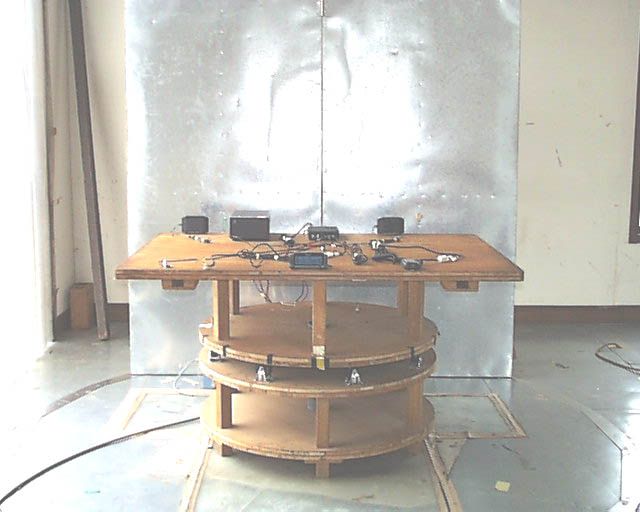
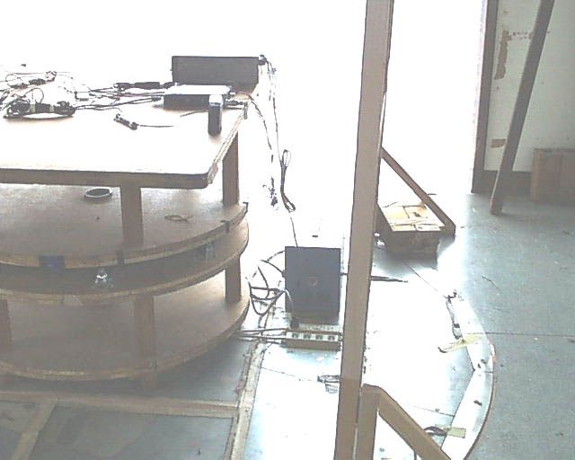
KENWOOD CORPORATION COMMUNICATION EQUIPMENT DIVISION SCANNING RECEIVER FCC ID : K4428451110 Report No.: Z02C-99246 Report Issue Date: September 16, 1999 ZACTA TECHNOLOGY CORPORATION YONEZAWA TESTING CENTER 4149-7 Hachimanpara 5-chome Yonezawa-shi Yamagata 992-1128 Japan FCC PART 15 SUBPART B CERTIFICATION REPORT for E-File Z02C-99246 Page 2/24 FCC ID: K4428451110 Zacta Technology Corp. TABLE OF CONTENTS CERTIFICATE COMPLIANCE..................................... 3 LABORATORY MEASUREMENTS................................... 5 JUSTIFICATION / ENGINEERING COMMENT ............................................ 5 SUMMURY OF TEST DATA ........................................................... 7 CONFIGURATION INFORMATION ..................................................... 9 SYSTEM CONFIGURATION .......................................................... 10 LABORATORY DESCRIPTION.................................... 11 DESCRIPTION FOR TEST SITE ..................................................... 11 DESCRIPTION OF CONDUCTION TESTING ............................................. 13 DESCRIPTION OF RADIATION TESTING .............................................. 14 DESCRIPTION OF ANTENNA POWER CONDUCTION TEST FOR RECEIVERS .................... 14 UNCERTAINTY ................................................................... 16 TEST SITE CONDITION & INSTRUMENTATION...... 17 TEST SITE CONDITION ........................................................... 17 TEST EQUIPMENT FOR CONDUCTION ................................................. 17 TEST EQUIPMENT FOR RADIATION .................................................. 19 SAMPLE OF FIELD STRENGTH CALCULATION .......................................... 20 TEST DATA.............................................................. 21 Z02C-99246 Page 3/24 FCC ID: K4428451110 Zacta Technology Corp. CERTIFICATE COMPLIANCE ZACTA TECHNOLOGY CORPORATION YONEZAWA TESTING CENTER 4149-7 Hachimanpara 5-chome Yonezawa-shi Yamagata 992-1128 Japan This device was measured pursuant to ANSI C63.4-1992 by Zacta Technology Corporation. The data in this application complies with the applicable technical standards as indicated in the measurements report and FCC Part 15 Class B limits. The EUT complies with section 15.37 “Transition provision for compliance with the rules”. APPLICANT : KENWOOD CORPORATION COMMUNICATION EQUIPMENT DIVISION FCC ID : K4428451110 FCC RULE PART : FCC Part 15 Subpart B, Docket 87-389 EQUIPMENT CLASS : Class B EUT TYPE : SCANNING RECEIVER FREQ. RANGE : 118MHz – 523.995MHz 800MHz – 1299.995MHz MAX USED FREQ. : 1299.995MHz DATE OF TEST : September 14,16, 1999 MEASUREMENT : ANSI C63.4-1992 TEST RESULT : PASS REPORT NO. : Z02C-99246 REMARKS : No modification was made during testing. Power cord is not connected to AC line. Zacta Technology Corporation certifies that no party to the application is subject to a denial of federal benefits, that include FCC benefits, pursuant to Section 5301 of the Anti-Drug Abuse Act of 1988, 21U.S.C. 853(a). Authorized by : Shin-ichi Abe General Manager, Zacta Technology Corporation Yonezawa Testing Center The results in this test report apply only to the samples tested. This report shall not be re-produced except in full without the Z02C-99246 Page 4/24 FCC ID: K4428451110 Zacta Technology Corp. written approval of Zacta Technology Corporation. Z02C-99246 Page 5/24 FCC ID: K4428451110 Zacta Technology Corp. LABORATORY MEASUREMENTS PURSUANT TO PART 15, SUBPART B COMPANY NAME : KENWOOD CORPORATION COMMUNICATION EQUIPMENT DIVISION EUT : SCANNING RECEIVER MODEL NO. : TM-D700A FCC ID : K4428451110 SERIAL NO. : N/A DATE OF TESTS : September 14,16, 1999 MEASUREMENT : ANSI C63.4-1992 FCC CLASS : B DISTANCE : 3m POWER SUPPLIED : DC 13.8V(From DC Power Supply) REPORT NO. : Z02C-99246 JUSTIFICATION / ENGINEERING COMMENT The detector function in frequency range of 30MHz-1GHz was set to Quasi-peak mode. Peak and average detectors were used for measurements above 1GHz. Used maximum frequency of this device is 1299.995MHz, therefore, we were measured up to 7GHz when Radiated Emission Test. Cables were manipulated to produce the worst case emissions. This device is composite device, and it is provided another Certification Filing No:Z02C-99247 as PC peripheral. All operating configuration, combination of Accessory: Microphone were measured. The worst case data were reported. Sufficient warm up time is proved for these testing. Frequency Rang: A Band 118MHz–523.995MHz B Band 136MHz-523.995MHz and 800MHz–1299.995MHz Four points of frequency: at bottom, middle, top of the band and scanning mode were measured, and SCAN mode was the worst case. Antenna power conduction for external receiving antenna were measured. Z02C-99246 Page 6/24 FCC ID: K4428451110 Zacta Technology Corp. ENGINEER : Takuya Osato Z02C-99246 Page 7/24 FCC ID: K4428451110 Zacta Technology Corp. SUMMURY OF TEST DATA RADIATION DATA OPERATING CONFIGURATION RESULT TEST MODE FREQUENCY MARGIN A Band 118MHz, B Band 800MHz 377.50MHz -16.1dB A Band 320MHz, B Band 1050.05MHz 1973.67MHz -14.3dB A Band 523.995MHz, B Band 1299.995MHz 2183.15MHz -9.7dB A Band 523.995MHz, B Band 523.995MHz 2183.15MHz -8.4dB A Band 523.995MHz B Band 330MHz 2183.15MHz -9.1dB A Band 118MHz B Band 136MHz 2352.73MHz -16.0dB A Band SCAN B Band SCAN 2288.67MHz -2.6dB CONDUCTION DATA OPERATING CONFIGURATION RESULT TEST MODE FREQUENCY MARGIN A Band SCAN B Band SCAN 1.359MHz -13.7dB Z02C-99246 Page 8/24 FCC ID: K4428451110 Zacta Technology Corp. POWER CONDUCTED EMISSION DATA KENWOOD TM -D700A Scan M ode A Band(MHz)B Band(MHz)FREQ.(MHz)READ(dBm ) Am p Gen(dB) Cable Loss(dB) Sum (dBm ) Limit(nw) Data(nw) M argin(nW) 151.995 - 190.85 -45.629.20.8-74.02.00 0.039811 -1.960189 248.625 380.500 425.46 -48.030.01.2-76.82.00 0.020941 -1.979059 403.750 - 843.62 -49.029.91.8-77.12.00 0.019724 -1.980276 514.405 - 951.09 -45.630.01.9-73.72.00 0.042855 -1.957145 437.245 - 995.98 -49.430.01.9-77.52.00 0.017673 -1.982327 461.200 - 1,055…
Text truncated - open the document above for the full version.
Contact Information
Applicant
Kazuyoshi Akaike(Manager)
Technical Contact
Zacta International CorporationYoshi Namiki
[email protected]818-727-1740
21220 Devonshire street, Suite 201 · Chatsworth, California · United States
Non-Technical Contact
Zacta International CorporationYoshi Namiki
[email protected]818-727-1740
Test Firm
Zacta Technology CorporationShin-ichi Abe
81-238-28-2880Fax: 81-238-28-2888
Technical Specifications
| # | Rule Parts | Frequency Range | Power Output | Tolerance |
|---|---|---|---|---|
| 3 | - | 894 MHz - 960 MHz | - | % |
Other Applications from JVC KENWOOD Corporation
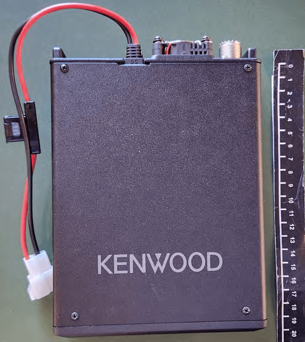
K44524000
Jan 23, 2026144/220/430MHz TRIBANDER
Equipment Class
CSR - Scanning Receiver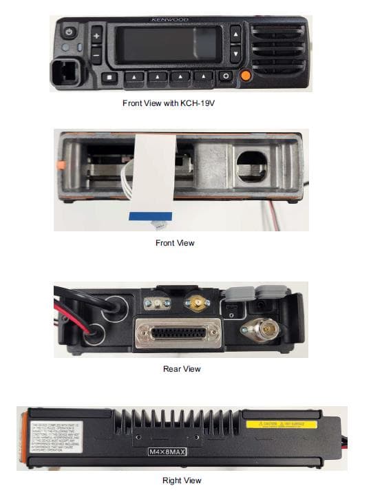
K44520000
Sep 05, 2024MULTIBAND DIGITAL TRANSCEIVER
Equipment Class
TNB - Licensed Non-Broadcast Station Transmitter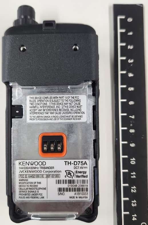
K44521000
Nov 08, 2023144/220/430MHz TRIBANDER
Equipment Class
DSS - Part 15 Spread Spectrum Transmitter
K44513201
May 18, 2023UHF REPEATER
Equipment Class
TNB - Licensed Non-Broadcast Station Transmitter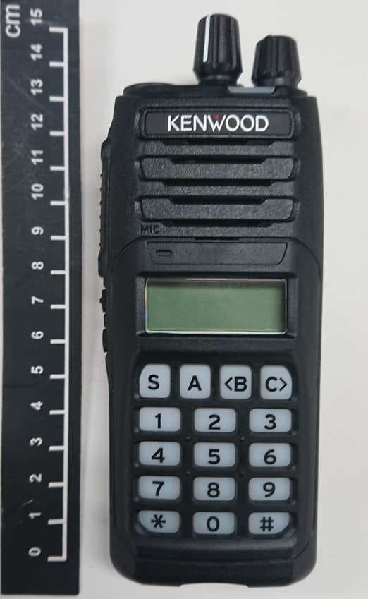
K44501001
May 25, 2021VHF TRANSCEIVER
Equipment Class
TNF - Licensed Non-Broadcast Transmitter Held to Face