K44521000144/220/430MHz TRIBANDER
JVC KENWOOD Corporation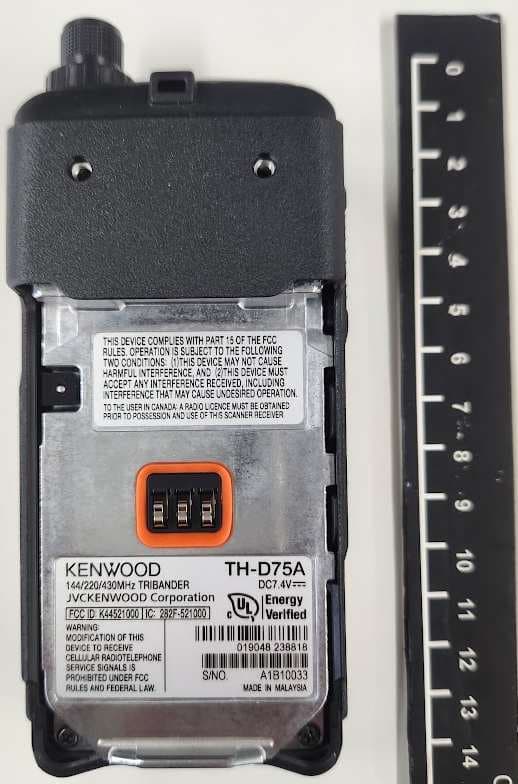
Click to zoom
Application Details
- Equipment Class
- DSS - Part 15 Spread Spectrum Transmitter
- Date of Grant
- Nov 08, 2023
- Application Purpose
- Original Equipment
- Date of Application
- Nov 08, 2023
- Equipment Note
- 144/220/430MHz TRIBANDER
- Frequency Range
- 2402.00000000 - 2480.00000000
- Company
- JVC KENWOOD Corporation
- Country
- Japan
Documents & Files
Document Text
Text extracted from the exhibit documents filed with the FCC. Open a document above to read the original.
Users Manual
B5A-4344-00 (K, E) USER GUIDE TH-D75A TH-D75E GUIDE DE L’UTILISATEUR GUÍA DEL USUARIO This User Guide covers only the basic operations of your transceiver. For the detailed instruction manual (User Manual), refer to the following URL. https://manual.kenwood.com/files/B5K-1131-00.pdf Ce Manuel de l’utilisateur concerne uniquement les opérations de base de votre émetteur-récepteur. Pour avoir accès un manuel de l'utilisateur détaillé (Mode d'emploi), reportez-vous à l’URL suivante. https://manual.kenwood.com/files/B5K-1131-00.pdf Este Manual del usuario sólo cubre las operaciones básicas de su transceptor. Para más detalles sobre el uso del manual de usuario (Manual de instrucciones), consulte el siguiente URL. https://manual.kenwood.com/files/B5K-1131-00.pdf This transceiver uses a software according to the following license agreements. *zlib LICENSE Copyright (C) 1995-2013 Jean-loup Gailly and Mark Adler This software is provided 'as-is', without any express or implied warranty. In no event will the authors be held liable for any damages arising from the use of this software. Permission is granted to anyone to use this software for any purpose, including commercial applications, and to alter it and redistribute it freely, subject to the following restrictions: 1 The origin of this software must not be misrepresented; you must not claim that you wrote the original software. If you use this software in a product, an acknowledgment in the product documentation would be appreciated but is not required. 2 Altered source versions must be plainly marked as such, and must not be misrepresented as being the original software. 3 This notice may not be removed or altered from any source distribution. Jean-loup Gailly ([email protected]) Mark Adler ([email protected]) *libpng LICENSE This copy of the libpng notices is provided for your convenience. In case of any discrepancy between this copy and the notices in the file png.h that is included in the libpng distribution, the latter shall prevail. COPYRIGHT NOTICE, DISCLAIMER, and LICENSE: If you modify libpng you may insert additional notices immediately following this sentence. This code is released under the libpng license. libpng versions 1.2.6, August 15, 2004, through 1.6.8, December 19, 2013, are Copyright (c) 2004, 2006-2013 Glenn Randers-Pehrson, and are distributed according to the same disclaimer and license as libpng-1.2.5 with the following individual added to the list of Contributing Authors Cosmin Truta libpng versions 1.0.7, July 1, 2000, through 1.2.5 - October 3, 2002, are Copyright (c) 2000-2002 Glenn Randers-Pehrson, and are distributed according to the same disclaimer and license as libpng-1.0.6 with the following individuals added to the list of Contributing Authors Simon-Pierre Cadieux Eric S. Raymond Gilles Vollant and with the following additions to the disclaimer: There is no warranty against interference with your enjoyment of the library or against infringement. There is no warranty that our efforts or the library will fulfill any of your particular purposes or needs. This library is provided with all faults, and the entire risk of satisfactory quality, performance, accuracy, and effort is with the user. libpng versions 0.97, January 1998, through 1.0.6, March 20, 2000, are Copyright (c) 1998, 1999 Glenn Randers-Pehrson, and are distributed according to the same disclaimer and license as libpng-0.96, with the following individuals added to the list of Contributing Authors: Tom Lane Glenn Randers-Pehrson Willem van Schaik libpng versions 0.89, June 1996, through 0.96, May 1997, are Copyright (c) 1996, 1997 Andreas Dilger Distributed according to the same disclaimer and license as libpng-0.88, with the following individuals added to the list of Contributing Authors: John Bowler Kevin Bracey Sam Bushell Magnus Holmgren Greg Roelofs Tom Tanner libpng versions 0.5, May 1995, through 0.88, January 1996, are Copyright (c) 1995, 1996 Guy Eric Schalnat, Group 42, Inc. For the purposes of this copyright and license, “Contributing Authors” is defined as the following set of individuals: Andreas Dilger Dave Martindale Guy Eric Schalnat Paul Schmidt Tim Wegner The PNG Reference Library is supplied “AS IS”. The Contributing Authors and Group 42, Inc. disclaim all warranties, expressed or implied, including, without limitation, the warranties of merchantability and of fitness for any purpose. The Contributing Authors and Group 42, Inc. assume no liability for direct, indirect, incidental, special, exemplary, or consequential damages, which may result from the use of the PNG Reference Library, even if advised of the possibility of such damage. Permission is hereby granted to use, copy, modify, and distribute this source code, or portions hereof, for any purpose, without fee, subject to the following restrictions: 1 The origin of this source code must not be misrepresented. 2 Altered versions must be plainly marked as such and must not be misrepresented as being the original source. 3 This Copyright notice may not be removed or altered from any source or altered source distribution. The Contributing Authors and Group 42, Inc. specifically permit, without fee, and encourage the use of this source code as a component to supporting the PNG file format in commercial products. If you use this source code in a product, acknowledgment is not required but would be appreciated. A “png_get_copyright” function is available, for convenient use in “about” boxes and the like: printf("%s",png_get_copyright(NULL)); Also, the PNG logo (in PNG format, of course) is supplied in the files “pngbar.png” and “pngbar.jpg” (88x31) and “pngnow.png” (98x31). Libpng is OSI Certified Open Source Software. OSI Certified Open Source is a certification mark of the Open Source Initiative. Glenn Randers-Pehrson glennrp at users.sourceforge.net December 19, 2013 *Md5 Copyright (C) 1999, 2000, 2002 Aladdin Enterprises. All rights reserved. This software is provided 'as-i…
Text truncated - open the document above for the full version.
Users Manual
26 BUILT-IN GPS FUNCTION ON/ OFF 1 Access Menu No. 400 and start the setting. 2 Select [On] or [Off]. [On]: Turns on the built-in GPS function. [Off]: Turns off the built-in GPS function. • When the built-in GPS r eceiver is On, the < > indicator appears on the display during positioning. • You must set the time zone beforehand, through Menu No. 950. • When determining your position for the first time after the power supply is turned On, the clock data is automatically set and is updated once per day thereafter. Displaying Position Information When the built-in GPS receiver is On, pressing [F], [MARK] will display “Latitude/longitude, time, altitude, heading, speed”, then press [] to cycle the display between “Latitude/ longitude, time, altitude, heading, speed” “Target point distance, Travel direction” “GPS satellite information”. • Press [] returns to the previous display. Latitude/longitude, Time, Altitude, Heading, Speed ① Latitude ② Longitude ③ Grid square locator ④ Altitude ⑤ Time ⑥ Heading ⑦ Speed Target point distance, Target direction Target direction Target point distance • When pressing [F] while the target point distance/ target direction is displayed, the North Up display (displays North as the top) changes to the Heading Up display (displays the current travel direction as the top) or vice-versa. In the Heading Up display, a “+” or “-” is used to help indicate the traveling direction. GPS satellite information Sky view ② Satellite signal-strength bars 2D: Latitude/Longitude positioning 3D: Latitude/L ongitude and Altitude positioning • The sky view shows the satellites you are receiving. The satellite signal-strength bars indicate the strength of each satellite you are receiving. A solid bar indicates that the GPS satellite is ready for use. • When only the frame of the signal-strength bar is displayed, no contact with the satellite has yet been made Note: ¡When GPS cannot be r eceived, turn the power ON in a clear environment (Open Sky). BUILT-IN GPS SETUP You can select whether to use the transceiver function together with the built-in GPS receiver function or to use the built-in GPS receiver function only. Built-in GPS Operation Mode 1 Access Menu No. 403. 2 Select [Normal] or [GPS Receiver]. Restar t information appears. 3 Pr ess [A/B] to restart the transceiver with the selected mode. [Normal]: The display continues to show your frequency. You can use it as a normal transceiver. [GPS R eceiver]: The display shows only GPS information. The transceiver transmit and receive capabilities are turned OFF, and only GPS operation is available. GPS Receiver mode display GPS 27 Key Operation in GPS Receiver Mode When set to “GPS Receiver”, you can operate only the following key functions. Key operations in [Latitude/longitude, Time, Altitude, Heading, Speed] Key NameOperation [] Switches to FM radio frequency screen when FM radio mode is On. [] Switches to [Target point distance and Heading] screen. [MODE] Switches to [Latitude and Longitude] copy selection screen. [MENU]Switches to the menu screen. [A/B]Switches to [Time] copy confirmation screen. [F] Switches between the North up and the Heading up. [MARK] Press [MARK]: Switches Mark waypoint list. Press [MARK] (1s): Switches to the registration mode of mark position. Key operations in [Target point distance, Target direction] Key NameOperation [ ] Switches to [Time, Altitude, Heading, and Speed] screen. [ ] Switches to [GPS satellite information] screen. [MODE] Switches to [Time, Altitude, Heading, and Speed] screen. [MENU]Switches to the menu screen. [A/B]Switches to [GPS satellite information] screen. [F] Switches between the North up and the Heading up. [MARK] Press [MARK] (1s): Switches to the registration mode of mark position. Key operations in [GPS satellite information] Key NameOperation [ ] Switches to [Target point distance and Target direction] screen. [ ] Switches to FM radio frequency screen when FM radio mode is On. [MODE] Switches to [Target point distance and Target direction] screen. [MENU]Switches to the menu screen. [A/B] Switches to FM radio frequency screen when FM radio mode is On. [MARK]Switches to the registration mode of mark position. Battery Saver (GPS Save) This function will turn the GPS power source Off after the programmed timer expires if position data is not determined during the maximum catching time (approximately 5 minutes). To prevent unnecessary battery consumption, when there are many reception satellites, the GPS is stabilized and position data can be determined, the GPS power source repeatedly turns On and Off. 1 Access Menu No . 404. 2 Set GPS Off time to [Off], [1], [2], [4], [8], or [Auto]. [OFF]: The built-in GPS receiver function is always On. [1min] to [8min]: When set to 1, 2, 4, or 8 minutes, the GPS off time starts at the selected duration if position data is not determined during the maximum catching time (approximately 5 minutes). [Auto]: When set to Auto, the GPS Off time starts at 1 minute for the first time, then progresses to 2 minutes, 4 minutes and 8 minutes each additional time. The GPS Off time remains at 8 minutes thereafter. However, after having determined your position for the duration, if the GPS cannot pinpoint your location, the GPS Off time will restart at 1 minute. Note: ¡Position pr ecision may be improved by setting the Battery Saver (GPS Save) function to “Off”. ¡When GPS cannot be r eceived, turn the power ON in a clear environment (Open Sky). GPS Data PC Output Turn this function on when you want to send the built-in GPS receiver data (NMEA) from the USB connector or Bluetooth. 1 Access Menu No. 405. 2 Set PC Output to [Off] or [On]. [Off]: The built-in GPS receiver data (NMEA) is not output from the USB connector or Bluetooth. [On]: The built-in GPS receiver data (NMEA) is output from the USB connector or Bluetooth. Note: ¡When the built-in GPS receiver data (NMEA) is output, the communication speed (baud rate) is fixed to 9,600 bps. ¡You can selec…
Text truncated - open the document above for the full version.
Attestation Statements
Oct. 27th 2023 Federal Communications Commission 7435 Oakland Mills Road Columbia, MD 21046 Attn: Reviewing Engineer RE: Attestation Statements for Model: TH-D75A, FCC ID: K44521000. To whom it may concern: We, JVCKENWOOD Corporation certifies that the equipment for which authorization is sought is not “covered” equipment prohibited from receiving an equipment authorization pursuant to section 2.903 of the FCC rules. We, JVCKENWOOD Corporation certifies that, as of the date of the filing of the application, the applicant is not identified on the Covered List as an entity producing “covered” equipment. Please contact me if you require any additional information. Sincerely, Kazuyoshi Akaike Engineering & Design Division 1-16-2, Hakusan, Midori-ku, Yokohama-shi, Kanagawa, 226-8525 Japan
Attestation Statements
1-16-2, Hakusan, Midori-ku, Yokohama-shi, Kanagawa, 226-8525 Japan Sep. 20th, 2023 Letter of Attestation Model: TH-D75A Scanning receiver (FCC ID: K44512000) This letter attests to the fact that JVCKENWOOD scanning receiver model TH-D75A meets the requirements of the FCC Rules, 15.121(a). Compliance is achieved through the following method(s): (1). The Microprocessor employed has internal flash memory, however the programming information cannot be read out from the Microprocessor, therefore it has same means of protection as a masked Microprocessor . (2). The Microprocessor is not to accept programming, selection, scanning or direct entry of Cellular band frequencies. (3). Filtering precludes reception of mixer images or harmonics of Cellular band frequencies. (4). It is subminiature SMD assembly and inaccessible multiplayer PCB construction, any attempts to modify the equipment to receive transmissions from the Cellular Radiotelephone Service likely will render the receiver inoperable. Sincerely, ___________________________________ Kazuyoshi Akaike Engineering & Design Division
Attestation Statements
Oct. 27th 2023 Federal Communications Commission 7435 Oakland Mills Road Columbia, MD 21046 Attn: Reviewing Engineer RE: Attestation Statements for Model: TH-D75A, FCC ID: K44521000. To whom it may concern: We, JVCKENWOOD Corporation designate an agent located in the United States for the purpose of accepting service of process on behalf of the applicant. Acknowledging the applicant’s acceptance of its obligation to maintain an agent for service of process in the United States for no less than one year after either the grantee has permanently terminated all marketing and importation of the applicable equipment within the U.S., or the conclusion of any Commission-related administrative or judicial proceeding involving the equipment, whichever is later. U.S. agent JVCKENWOOD USA Corporation Address: 1440 Corporate Drive, Irving, TX 75038 e-mail address: [email protected] FRN: 0005743653 Please contact me if you require any additional information. Sincerely, U.S agent Applicant Angie Seay Communications Sector JVCKENWOOD USA Corporation FRN: 0005743653 Kazuyoshi Akaike Engineering & Design Division JVCKENWOOD Corporation FRN: 0008154510 1-16-2, Hakusan, Midori-ku, Yokohama-shi, Kanagawa, 226-8525 Japan
Cover Letter(s)
DATE: October 12, 2023 Federal Communications Commission 7435 Oakland Mills Road Columbia, MD 21046 RE: LETTER OF AGENT AUTHORIZATION To whom it may concern: We, the undersigned, hereby authorize HCT Co.,LTD. to act on our behalf in all matters relating to applications for equipment authorization, including the signing of all documents relating to these matters. Any and all acts carried out by HCT Co.,LTD. on our behalf shall have the same effect as acts of our own. We also hereby certify that no party to this application is subject to a denial of benefits, including FCC benefits, pursuant to Section 5301 of the Anti-Drug Abuse Act of 1988,21 U.S.C.862. This agreement expires one year from the current date. Sincerely, Signature Junichi Okada Kashima Laboratory Manager Intertek Japan K.K.
Cover Letter(s)
Sep. 20th, 2023 Federal Communications Commission 7435 Oakland Mills Road Columbia, MD 21046 Attn: Reviewing Engineer RE: LETTER OF AGENT AUTHORIZATION To whom it may concern: We, the undersigned, hereby authorize any individual within Intertek Japan K.K. to act on our behalf in all matters relating to application for equipment authorization, including the signing of all documents relating to these matters. We also hereby certify that no party to the application authorized hereunder is subject to the denial of benefits, including FCC benefits, pursuant to Section 5301 of the Anti-Drug Abuse Act of 1988,21 U.S.C.862. This agreement expires one year from the current date. Sincerely, Kazuyoshi Akaike Engineering & Design Division 1-16-2, Hakusan, Midori-ku, Yokohama-shi, Kanagawa, 226-8525 Japan
Cover Letter(s)
Sep. 20th 2023 Federal Communications Commission 7435 Oakland Mills Road Columbia, MD 21046 Attn: Reviewing Engineer RE: CONFIDENTIALITY REQUEST FOR MODEL: TH-D75A, FCC ID: K44512000 To whom it may concern: This letter serves as an official request for permanent confidentiality pursuant to 47 CFR Section 0.459 of the Commission Rules. We have requested that the Block Diagram, Schematic Diagrams, Circuit Description, Parts List and Active Devices required to be submitted with this application be withheld from public review. The documents are company proprietary information that could never get into the possession of our competition. Please contact me if you require any additional information. Sincerely, Kazuyoshi Akaike Engineering & Design Division 1-16-2, Hakusan, Midori-ku, Yokohama-shi, Kanagawa, 226-8525 Japan
External Photos
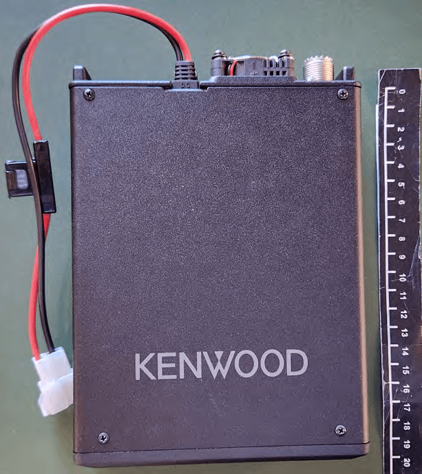
FCC ID: K44521000 IC: 282F-521000 Front View FCC ID: K44521000 IC: 282F-521000 Rear View FCC ID: K44521000 IC: 282F-521000 Top View Bottom View FCC ID: K44521000 IC: 282F-521000 Side View
ID Label/Location Info
FCC ID: K44512000 IC: 282F-512000
Internal Photos
FCC ID: K44521000 IC: 282F-521000 CONTROL Unit with Shielding case CONTROL Unit without Shielding case CONTROL Unit with Shielding case CONTROL Unit without Shielding case FCC ID: K44521000 IC: 282F-521000 Bluetooth Antenna
RF Exposure Info
Intertek Japan K.K. 1283 Yadoriki, Matsuda, Ashigarakami-gun, Kanagawa 258-0001 Japan Tel +81 465 89 2316 / Fax +81 465 89 2160 October 30, 2023 Intertek Japan K.K. 1283 Yadoriki, Matsuda, Ashigarakami-gun, Kanagawa-ken 258-0001 Japan To whom it may concern, We, Intertek Japan K.K., hereby declare that Bluetooth(BR, EDR) Module installed into model: TH-D75A (FCC ID:K44521000) of JVCKENWOOD Corporation., is exempt from RF exposure SAR evaluation as its output power meets the exclusion limits stated in KDB 447498D01(v06). KDB 447498D01(v06) has the following exclusion for portable devices: The 1g and 10g SAR test exclusion thresholds for 100 MHz to 6 GHz at test separation distances ≤ 50 mm are determined by: [(max. power of channel, including tune-up tolerance, mW)/(min. test separation distance, mm)] ·[√f(GHz)] ≤ 3.0 for 1 g SAR and ≤ 7.5 for 10 g extremity SAR, where •f(GHz) is the RF channel transmit frequency in GHz •Power and distance are rounded to the nearest mW and mm before calculation •The result is rounded to one decimal place for comparison The test exclusions are applicable only when the minimum test separation distance is ≤ 50 mm and for transmission frequencies between 100 MHz and 6 GHz. When the minimum test separation distance is < 5 mm, a distance of 5 mm is applied to determine SAR test exclusion. This device has f = 2.48 GHz and distance = 5 mm (minimum separation distance: 5mm was used in the calculation) and the maximum average output power was 3.89 mW So for this device: 3.89 mW[maximum average output power]/5 mm[minimum separation distance]*√2.48 = 1.23 *This is less than 3.0, so no SAR is required. Even taking into account the tolerance, this device can be satisfied with the limits. Thank you for your attention to this matter. Hideaki Kosemura Technical Manager Intertek Japan K.K.
Test Report
© 2022 Intertek Japan K.K. Page 1 of 93 LFT-FJP-TE054 / Effective Date: 30 Nov 2022 TEST REPORT REGULATIONS : FCC Part15 C §15.247 RSS-247 Issue 2 (2017-02) Applicant Testing Laboratory JVCKENWOOD Corporation 1-16-2, Hakusan, Midori-ku, Yokohama-shi Kanagawa, 226-8525 Japan Tel.: +81 45 939 6254 / Fax.: +81 45 939 7097 Intertek Japan K.K. Matsuda Laboratory (Open area test site) 1283 Yadoriki, Matsuda-machi, Ashigarakami-gun, Kanagawa-ken, 258-0001 Japan Tel.: +81 465 89 2316 URL: http://www.japan.intertek-etlsemko.com Equipment Type 144/220/430MHz TRIBANDER Trademark KENWOOD Model(s) TH-D75A Serial No. FES1 K-51 FES1 K-52 (for Antenna Port Conductive testing) Equipment Authorization Certification FCC ID K44521000 ISED CN and UPN No. 282F-521000 PMN and HVIN (ISED) TH-D75A Test Result Complied Report Number 23070289JMA-001 Original Issue Date October 31, 2023 This report is for the exclusive use of Intertek's Client and is provided pursuant to the agreement between Intertek and its Client. Intertek's responsibility and liability are limited to the terms and conditions of the agreement. Intertek assumes no liability to any party, other than to the Client in accordance with the agreement, for any loss, expense or damage occasioned by the use of this report. Only the Client is authorized to permit copying or distribution of this report and then only in its entirety. (This test report shall not be reproduced except in full, without written approval of Intertek Japan K. K.) Any use of the Intertek name or one of its marks for the sale or advertisement of the tested material, product or service must first be approved in writing by Intertek. The observations and test results in this report are relevant only to the sample tested. This report by itself does not imply that the material, product, or service is or has ever been under an Intertek certification program. Approved by Tested by Hideaki Kosemura [ Reviewer ] Daichi Mitsunaga [ Engineer ] Tested by Kenji Kitta [ Engineer ] NVLAP LAB CODE 600234-0 NVLAP accreditation are valid for RSS-247. FCC Part15C is outside the NVLAP scope. This report contains data that are not covered by the NVLAP accreditation. The report must not be used by the client to claim product certification, approval, or endorsement by NVLAP, NIST, or any agency of the U.S. Government. VLAC-008 Report No.: 23070289JMA-001 Original: October 31, 2023 FCC ID: K44521000 ISED CN and UPN No.: 282F-521000 © 2022 Intertek Japan K.K. Page 2 of 93 LFT-FJP-TE054 / Effective Date: 30 Nov 2022 Responsible Part y of Test Item (Product) Responsible Party : Add. : Te l . : Fax. : Contact Person : Report No.: 23070289JMA-001 Original: October 31, 2023 FCC ID: K44521000 ISED CN and UPN No.: 282F-521000 © 2022 Intertek Japan K.K. Page 3 of 93 LFT-FJP-TE054 / Effective Date: 30 Nov 2022 TABLE OF CONTENTS Page SECTION 1. GENERAL INFORMATION .................................................................................................... 4 SECTION 2. SUMMARY OF TEST RESULTS ............................................................................................ 5 SECTION 3. EQUIPMENT UNDER TEST ................................................................................................... 6 SECTION 4. SUPPORT EQUIPMENT ........................................................................................................ 8 SECTION 5. USED CABLE(S) .................................................................................................................... 9 SECTION 6. TEST CONFIGURATION ...................................................................................................... 10 SECTION 7. OPERATING CONDITION ..................................................................................................... 11 SECTION 8. UNCERTAINTY ..................................................................................................................... 12 SECTION 9. TEST DATA ........................................................................................................................... 13 9.1 20 dB Bandwidth and 99 % Occupied Bandwidth ........................................................................... 13 9.2 Maximum Peak Output Power ......................................................................................................... 14 9.3 Carrier Frequency Separation ......................................................................................................... 16 9.4 Number of Hopping Frequency ....................................................................................................... 17 9.5 Time of Occupancy ......................................................................................................................... 18 9.6 Radiated Spurious Emissions and Band Edge of Restrict Band ..................................................... 20 9.7 Band Edge of Authorized Frequency Band ..................................................................................... 30 9.8 Conducted Spurious Emissions ...................................................................................................... 33 9.9 AC Conducted Emissions ................................................................................................................ 34 9.10 Receiver Spurious Emissions ........................................................................................................ 47 SECTION 10. LIST AND DIAGRUM OF MEASURING INSTRUMENTS ................................................... 50 ANNEX .................................................................................................................................................. 56 A. HARD COPY OF SPECTRUM PLOTS ............................................................................................. 57 B. PHOTOGRAPHS OF EMISSION SET-UP............................................................................................ C. PHOTOGRAPHS …
Text truncated - open the document above for the full version.
Test Report
FCC ID: K44521000 IC: 282F-521000 TH-D75A Bluetooth Antenna Specification and Description Output Power: 2.5mW (Power Class 2) +4.0dBm (Min. -1dBm, Max. +6.0dBm) Current consumption: 100 mA max. Version 3.0 (non HS) Channel 79 ch hopping, 1MHz step Modulation method FHSS (GFSK, π/4dPSK, 8DPSK) Antenna type Wire Antenna Antenna gain -2.16 dBi (max) ●Photos of the Antenna ●Antenna Gain Test Equipment Horn Antenna : SCHWARZBECK BBHA 9120 D (Cal. Expiration date : 08/31/2024) Signal Analyzer : ROHDE&SCHWARZ FSV (Cal. Expiration date : 05/31/2024) ●Test Location 1-16-2 Hakusan, Midori-ku, Yokohama-shi, Kanagawa 226-8525, Japan JVCKENWOOD Corporation FCC ID: K44521000 IC: 282F-521000 ●Test Set up Photos ●Polar Plot 2.480GHz 0-10-20-30 90 60 30 0 330 300 270 240 210 180 150 120 (dBi) Angle(degree) Bluetooth Antenna Radiation Pattern 2480MHz Y-X Plane Horizontal polarization Vertical polarization 0-10-20-30 90 60 30 0 330 300 270 240 210 180 150 120 (dBi) Angle(degree) Bluetooth Antenna Radiation Pattern 2480MHz Z-Y Plane Horizontal polarization Vertical polarization 0-10-20-30 90 60 30 0 330 300 270 240 210 180 150 120 (dBi) Angle(degree) Bluetooth Antenna Radiation Pattern 2480MHz Z-X Plane Horizontal polarization Vertical polarization
Test Setup Photos
Report No.: 23070289JMA-001 Original: October 31, 2023 FCC ID: K44521000 ISED CN and UPN No.: 282F-521000 © 2022 Intertek Japan K.K. Page 1 of 7 LFT-FJP-TE054 / Effective Date: 30 Nov 2022 B. PHOTOGRAPHS OF EMISSION SET-UP Report No.: 23070289JMA-001 Original: October 31, 2023 FCC ID: K44521000 ISED CN and UPN No.: 282F-521000 © 2022 Intertek Japan K.K. Page 2 of 7 LFT-FJP-TE054 / Effective Date: 30 Nov 2022 B.1 Radiated Spurious Emissions below 30 MHz Report No.: 23070289JMA-001 Original: October 31, 2023 FCC ID: K44521000 ISED CN and UPN No.: 282F-521000 © 2022 Intertek Japan K.K. Page 3 of 7 LFT-FJP-TE054 / Effective Date: 30 Nov 2022 B.2 Radiated Spurious Emissions 30 – 1000 MHz Report No.: 23070289JMA-001 Original: October 31, 2023 FCC ID: K44521000 ISED CN and UPN No.: 282F-521000 © 2022 Intertek Japan K.K. Page 4 of 7 LFT-FJP-TE054 / Effective Date: 30 Nov 2022 B.3 Radiated Spurious Emissions above 1 GHz Note : Maintaining 10cm spacing between all the equipment cabinets. Report No.: 23070289JMA-001 Original: October 31, 2023 FCC ID: K44521000 ISED CN and UPN No.: 282F-521000 © 2022 Intertek Japan K.K. Page 5 of 7 LFT-FJP-TE054 / Effective Date: 30 Nov 2022 B.4 AC Conducted Emissions Note : Maintaining 10cm spacing between all the equipment cabinets. Report No.: 23070289JMA-001 Original: October 31, 2023 FCC ID: K44521000 ISED CN and UPN No.: 282F-521000 © 2022 Intertek Japan K.K. Page 6 of 7 LFT-FJP-TE054 / Effective Date: 30 Nov 2022 C. PHOTOGRAPHS OF EUT Axis Report No.: 23070289JMA-001 Original: October 31, 2023 FCC ID: K44521000 ISED CN and UPN No.: 282F-521000 © 2022 Intertek Japan K.K. Page 7 of 7 LFT-FJP-TE054 / Effective Date: 30 Nov 2022 C.1 EUT Axis X Y Z
Contact Information
Applicant
Kazuyoshi Akaike(Manager)
Test Firm
Intertek Japan K.K.(Matsuda laboratory)Tadashi Katsube
Technical Specifications
| # | Rule Parts | Frequency Range | Power Output |
|---|---|---|---|
| 1 | 15C | 2.40 GHz - 2.48 GHz | 2.50 mW |
Other Applications from JVC KENWOOD Corporation
K44524000
Jan 23, 2026144/220/430MHz TRIBANDER
Equipment Class
CSR - Scanning Receiver
K44520000
Sep 05, 2024MULTIBAND DIGITAL TRANSCEIVER
Equipment Class
TNB - Licensed Non-Broadcast Station Transmitter
K44513201
May 18, 2023UHF REPEATER
Equipment Class
TNB - Licensed Non-Broadcast Station Transmitter
K44501001
May 25, 2021VHF TRANSCEIVER
Equipment Class
TNF - Licensed Non-Broadcast Transmitter Held to Face
K44501103
May 17, 2021UHF TRANSCEIVER
Equipment Class
TNF - Licensed Non-Broadcast Transmitter Held to Face