K4435583120UHF FM Transceiver
JVC KENWOOD Corporation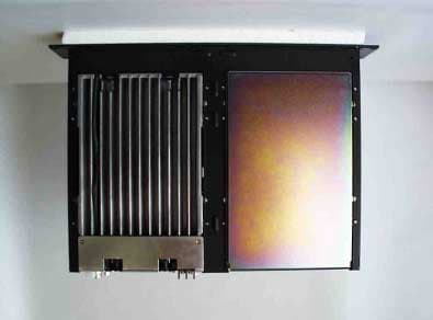
Click to zoom
Application Details
- Equipment Class
- TNB - Licensed Non-Broadcast Station Transmitter
- Date of Grant
- Nov 01, 2004
- Application Purpose
- Original Equipment
- Date of Application
- Nov 01, 2004
- Equipment Note
- UHF FM Transceiver
- Frequency Range
- 480.00000000 - 512.00000000
- Company
- JVC KENWOOD Corporation
- Country
- Japan
Documents & Files
Document Text
Text extracted from the exhibit documents filed with the FCC. Open a document above to read the original.
Users Manual
TKR-851-2 FCC ID: K4435583120 INSTRUCTION MANUAL TKR-851-2 THANK YOU! We are grateful you purchased this KENWOOD repeater. We believe this easy-to-program repeater will be highly effective in your communications system, and will keep personnel operating at peak efficiency. KENWOOD incorporates the latest in advanced technology into all of our products. As a result, we feel strongly that you will be pleased with the quality and features of this product. FEATURES • You can easily program channel data using the KPG-91D software on a PC. • You can recall 1 of 16 preset channels using either a PF key or the external control line. • The firmware can be written to the Flash memory through an external source. • QT/DQT signalling can be programmed on each channel. It simultaneously decodes up to 16 different QT/DQT tones. • Air Remote Control Function. • The interface port can be used with external equipment, such as a repeater controller. • The repeater has multi-mode capability. Wide: 30 kHz / Narrow: 15 kHz (TKR-751; K type only) Wide: 25 kHz/ Narrow: 12.5 kHz (TKR-751/TKR-851) • You can adjust the following functions from a PC: • Squelch • RX Audio Signal Output (RA) • RX Detector Signal Output (RD) • RX Frequency • RF Output Power • Maximum Deviation • TX Audio Input (TA) • Signaling Deviation (TD) • DQT Balance • QT Deviation • DQT Deviation • Test Tone Deviation • CW ID Deviation • Repeat Gain • TX Frequency • DTMF Deviation • Courtesy Tone Deviation • Battery Operating Tone Deviation • Battery Warning Tone Deviation • Power Down Detect • 5 Tone Deviation (M type only) TKR-851-2 FCC ID: K4435583120 PRECAUTIONS • Do not expose the unit to rain or moisture; to prevent fire or electric shock. • Do not open the unit under any circumstances; to avoid risk of electric shock. • Do not expose the unit to long periods of direct sunlight, nor place it close to heating appliances. • Do not place the unit in excessively dusty and/or humid areas, nor on unstable surfaces. • If you detect an abnormal odor or smoke coming from the unit, disconnect the power from the unit immediately. Contact your KENWOOD service center or dealer. NOTICES TO THE USER UNPACKING AND CHECKING EQUIPMENT Note: The following unpacking information is for use by your KENWOOD dealer, an authorized KENWOOD service facility, or the factory. Carefully unpack the repeater. We recommend that you identify the items listed in the following table before discarding the packing material. If any items are missing or have been damaged during shipment, file a claim with the carrier immediately. Item Part Number Quantity Hardware fixture J21-8402-#4 1 Front Glass B10-2635-#4 1 Filter B11-1259-#4 1 Cushion G13-1801-#4 4 Cushion G13-1802-#4 4 Foot J02-0475-#5 2 Foot J02-0492-#4 2 Grommet J59-0302-#5 2 Handle K01-0418-#5 1 Screw N30-4006-46 2 Screw N35-3006-45 5 DC Cord E30-3427-#5 1 Connector Cable E31-3228-#5 1 Fuse F06-1032-#5 1 Instruction Manual B62-1775-## 1 Warranty Card 1 FCC WARNING This equipment generates or uses radio frequency energy. Changes or modifications to this equipment may cause harmful interference unless the modifications are expressly approved in the instruction manual. The user could lose the authority to operate this equipment if an unauthorized change or modification is made. ** GOVERNMENT LAW PROHIBITS THE OPERATION OF UNLICENSED RADIO TRANSMITTERS WITHIN THE TERRITORIES UNDER GOVERNMENT CONTROL. ** ILLEGAL OPERATION IS PUNISHABLE BY FINE OR IMPRISONMENT OR BOTH. ** REFER SERVICE TO QUALIFIED TECHNICIANS ONLY. CAUTION: This repeater is intended for use as a fixed base station with the antenna located outdoors on the rooftop or on antenna tower. TKR-851-2 FCC ID: K4435583120 INSTALLATION To install the handles onto the front panel of the repeater, align the handles with the holes on the front panel, then secure the handles using the supplied screws. Please consult your dealer for installing the repeater and antenna. MICROPHONE Connect an optional KMC-30, KMC-27A, KMC-27B, or KMC-9C KENWOOD microphone to the MIC jack on the front panel. CONTROLS AND FUNCTIONS ** Front Panel 1 Speaker 2 CH/STATUS Display Two, 7-segment digits display the channel number or status. 3 VOLUME control Rotate to adjust the volume. 4 DC SOURCE switch 5 Power indicator Lights green when power is applied from the DC 13.6V jack. Lights red when power is applied from the BACKUP battery terminal. 6 Mic jack Connect a microphone to this 8-pin modular jack. 7 Programmable Function keys Press these keys to activate their programmable functions. 8 BUSY indicator Lights green while a signal is being received. 9 TX indicator Lights red while transmitting. ** Rear Panel 1 TX OUT jack Connect a TX antenna or a duplexer ti this receptacle. 2 CONTROL I/O jack Connect an external programming device or repeater controller to this DB-25 interface. 3 FUSE Insert 10 A blade fuses into these fuse holders. 4 RX IN jack Connect a RX antenna or a duplexer to this BNC receptacle. 5 DC 13.6V jack Connect a 13.6 V DC power supply to this jack. 6 BACKUP battery terminal 7 TEST/SPKR jack Test input/output jack. Connect an external speaker to this jack. TKR-851-2 FCC ID: K4435583120 REPEATER OPERA TION Note: Please consult your dealer for programming the repeater. When power is applied to the unit, the POWER indicator lights. • Green when using the main DC jack. • Red when using the Backup terminal. Rotate the VOLUME control to adjust the volume. The BUSY indicator lights green while receiving a signal and the TX indicator lights red while transmitting. TRANSCEIVER OPERA TION ** Receive Adjust the volume to your desired level. You may need to readjust the volume when you receive a message from your dispatcher or another member in your fleet. • The BUSY indicator lights green while a signal is being received. ** Transmit 1 Listen to the channel before transmitting, to make sure it is not being used. 2 Press the microphone PTT switch, then speak in your normal speaking voice. •…
Text truncated - open the document above for the full version.
Cover Letter(s)
Oct. 20th, 2004 Federal Communications Commission 7435 Oakland Mills Road Columbia, MD 21046 Attn: Reviewing Engineer RE: CONFIDENTIALITY REQUEST FOR MODEL: TKR-851-2, FCC ID: K4435583120. To Whom It May Concern: This letter serves as an official request for permanent confidentiality pursuant to 47 CFR Section 0.459 of the Commission Rules. We have requested that the Block Diagram, Schematic Diagrams, Circuit Description, Parts List, Active Devices and Tuning Procedure required to be submitted with this application be withheld from public review. The documents are company proprietary information that could never get into the possession of our competition. Please contact me if you require any additional information. Sincerely, Tamaki Shimamura Communication Equipment Division Kenwood Corporation
Cover Letter(s)
May 20th, 2004 Federal Communications Commission 7435 Oakland Mills Road Columbia, MD 21046 Attn: Reviewing Engineer RE: LETTER OF AGENT AUTHORIZATION To Whom It May Concern: We, the undersigned, hereby authorize Akzo Nobel K.K. to act on our behalf in all matters relating to application for equipment authorization, including the signing of all documents relating to these matters. We also hereby certify that no party to the application authorized hereunder is subject to the denial of benefits, including FCC benefits, pursuant to Section 5301 of the Anti-Drug Abuse Act of 1988,21 U.S.C.862. This agreement expires one year from the current date. Sincerely, Tamaki Shimamura Communication Equipment Division Kenwood Corporation
Cover Letter(s)
Akzo Nobel K. K. EMC Division Bancho Kaikan 12-1, Gobancho, Chiyoda-ku Tokyo 102-0076 Japan Tel.+81 3 5210 5411 Fax.+81 3 5216 2860 October 20, 2004 Federal Communications Commission Office of Engineering and Technology 7435 Oakland Mills Road Columbia, MD 21046 RE: LETTER OF AGENT AUTHORIZATION To Whom It May Concern: We, the undersigned, hereby authorize MET Laboratories, Inc. to act on our behalf in all matters relating to application for equipment authorization, including the signing of all documents relating to these matters. We also hereby certify that no party to the application authorized hereunder is subject to the denial of benefits, including FCC benefits, pursuant to Section 5301 of the Anti-Drug Abuse Act of 1988,21 U.S.C.862. This authorization expires one year from the current date. Sincerely, Junichi Okada Group Leader Tokyo Office EMC Division Akzo Nobel K. K.
External Photos
TKR-851-2 FCC ID: K4435583120 Rear View Front View TKR-851-2 FCC ID: K4435583120 Top View Bottom View TKR-851-2 FCC ID: K4435583120 Left View Right View
ID Label/Location Info
TKR-851-2 FCC ID: K4435583120 Label Location
ID Label/Location Info
TKR-851-2 FCC ID:K4435583120
Internal Photos
TKR-851-2 FCC ID: K4435583120 Display Component Side View Display Foil Side View TKR-851-2 FCC ID: K4435583120 TX-RX A/2 Component Side View TX-RX A/2 Foil Side View TKR-851-2 FCC ID: K4435583120 TX-RX B/2 Component Side View TX-RX B/2 Foil Side View TKR-851-2 FCC ID: K4435583120 Final Component Side View Final Foil Side View
RF Exposure Info
Maximum Permissible Exposure (MPE) Evaluation Applicant:Kenwood Corporation Equipmen t:UHF FM REPEATER Model No.:TKR-851-2 FCC ID:K4435583120 MPE Calculations According to the OET Bulletin 65 (Edition 97-01) Where: S=Power density (in appropriate units, e.g. mW/cm 2 ) P=Power input to antenna (in appropriate units, e.g., mW) G=Power gain of the antenna in the direction of interest relative to an isotropic radiator R=Distance to the center of radiation of the antenna (appropriate units, e.g., cm) Tx Frequency=480 to 512 (MHz) Maximum peak power =(dBm)(=25W) Antenna gain=(dBi) S=(mW/cm 2 ) P=(mW) (=Maximum peak power x 120% x Dutycycle 50%) G=(numeric) R=(cm) P = Value calculated according to CFR Part 90.205(q) Calculated minimum separation distance from antenna :78.23 (cm) 1.64 78.23 43.98 2.15 0.32 15000.00 S PG R π4 = 2 4R PG S π =
RF Exposure Info
MANDATORY SAFETY INSTRUCTIONS TO INSTALLERS AND USERS • Use only manufacturer or dealer supplied antenna. • Antenna Minimum Safe Distance: 120 cm (4 feet), 50% duty Cycle. • Antenna Gain: 0 dBd referenced to a dipole. The Federal Communications Commission has adopted a safety standard for human exposure to RF (Radio Frequency) energy which is below the OSHA (Occupational Safety and Health Act) limits. • Antenna Mounting: The antenna supplied by the manufacturer or radio dealer must not be mounted at a location such that during radio transmission, any person or persons can come closer than the above indicated minimum safe distance to the antenna, i.e. 120 cm (4 feet) , 50% duty Cycle. • To comply with current FCC RF Exposure limits, the antenna must be installed at or exceeding the minimum safe distance shown above, and in accordance with the requirements of the antenna manufacturer or supplier. • Vehicle installation: The antenna can be mounted at the center of a vehicle metal roof or trunk lid, if the minimum safe distance is observed. • Base Station Installation: The antenna should be fixed-mounted on an outdoor permanent structure. RF Exposure compliance must be addressed at the time of installation. Antenna substitution: Do not substitute any antenna for the one supplied or recommended by the manufacturer or radio dealer. You may be exposing person or persons to excess radio frequency radiation. You may contact your radio dealer or the manufacturer for further instructions. Maintain a separation distance from the antenna to person(s) of at least 120 cm (4 feet) , 50% duty Cycle. You, as the qualified end-user of this radio device must control the exposure conditions of bystanders to ensure the minimum separation distance (above) is maintained between the antenna and nearby persons for satisfying RF Exposure compliance. The operation of this transmitter must satisfy the requirements of Occupational/Controlled Exposure Environment, for work-related use, transmit only when person(s) are at least the minimum distance from the properly installed, externally mounted antenna. Transmit only when people outside the vehicle are at least the recommended minimum lateral distance away from the antenna/vehicle
Test Report
TRUE TRUE 4 Regulation : FCC Part 2, 22, 90, 90.210 Kenwood CorporationAkzo Nobel K. K. Kashima No.1 , No.3 , No.10 site 1-16-2, Hakusan, Midori-ku, Yokohama-shiFCC Registration Number : 90433 Kanagawa, 226-8525 Japan1, Oaza Sunayama, Hasaki-machi, Kashima-gun Tel.: +81 45 939 6254 Fax.: +81 45 939 7093Ibaraki-ken, 314-0255 Japan Tel.: +81 479 40 1097 Fax.: +81 479 46 1788 e-mail: [email protected] URL: www.akzoemc.co.jp Equipment typeUHF FM REPEATER TrademarkKENWOOD Model(s)TKR-851-2 Serial No.None FCC ID K4435583120 Measurement MethodANSI/TIA/EIA-603 No deviation Test ResultComplied Report NumberANKK-104210 Report issue date Approved byTested by Takeshi Yamanaka / [Site Manager]Naoki Ikeda This equipment has been shown to be capable of compliance with the applicable standard(s) as indicated in the test report. I attest to the accuracy of data. All measurements reported herein were performed by me or were made under my supervision and are correct to the best of my knowledge and belief. I assume full responsibility for the completeness of these measurements and vouch for the qualifications of all persons taking them. This test report shall not be reproduced partially, or in full, without the prior written approval of Akzo Nobel K. K. The results and statements contained in this report pertain only to the equipment evaluated. Applicant CERTIFICATE OF COMPLIANCE Testing Laboratory Deviation from standard(s) October 13, 2004 ©Akzo Nobel K. K. EMC Div.Page 1 of 27Version 6.1 Report No : ANKK-104210FCC ID : K4435583120 TABLE OF CONTENTS Page SECTION 1.GENERAL INFORMATION3 SECTION 2.TEST AND MEASUREMENT DATA4 SECTION 3.MEASUREMENT RESULT5 SECTION 4.TEST DATA 4.1Carrier Output Power (Conducted)6 4.2Unwanted Emissions (Transmitter Conducted)7 4.3Field Strength of Spurious Radiation9 4.4Emission Masks (Occupied Bandwidth)12 4.5Transient Frequency Behavior15 4.6Audio Frequency Response / Audio Low Pass Filter (Voice Input)18 4.7Modulation Limiting20 4.8Frequency Stability (Temperature Variation)23 4.9Frequency Stability (Voltage Variation)25 4.10Necessary Bandwidth and Emission Bandwidth26 SECTION 5.VALIDITY OF TEST REPORT27 SECTION 6. DESCRIPTION OF TEST SITE27 APPENDIXPHOTOGRAPHS ©Akzo Nobel K. K. EMC Div.Page 2 of 27Version 6.1 Report No : ANKK-104210FCC ID : K4435583120 SECTION 1. GENERAL INFORMATION APPLICANT INFORMATION Company:Kenwood Corporation Address:1-16-2, Hakusan, Midori-ku, Yokohama-shi, Kanagawa, 226-8525 Japan Attenuation:Tamaki Shimamura Manager, Communications Equipment Division Telephone number :+81 45 939 6254 Fax number:+81 45 939 7093 DESCRIPTION OF TEST ITEM Kind of EUT:Fixed base station Condition of EUT:Pre Production Type:Fixed Trademark:KENWOOD Model number:TKR-851-2 Serial number:None Emission Designation:16K0F3E(Wide) / 11K0F3E(Narrow) Frequency Range:480 to 512 MHz Output Power:1 to 25 W Number of Channel:16 Channel Spacing:5 kHz (Wide) / 2.5 kHz (Narrow) Antenna Impedance:50 Ω Norminal TEST PERFORMED EUT Received: Test started: Test completed: Temperature:23.0 to 27.0 degrees C Humidity:45.0 to 67.0 % Atmospheric:100.4 to 103.0 kPa Voltage:DC 13.6 V Frequency:None TEST TRACABILITY ABBREVIATIONS September 27, 2004 September 27, 2004 EUT = Equipment Under Test D.R.G. Antenna = Double Rigid Guide Antenna October 08, 2004 Cal Exp. = Calibration Expire Tracability to national standards of test result is achieved by means of calibration tractability to national or international standards. ©Akzo Nobel K. K. EMC Div.Page 3 of 27Version 6.1 Report No : ANKK-104210FCC ID : K4435583120 SECTION 2. TEST AND MEASUREMENT DATA All test and measurements indicated in this document were performed in accordance with the Code of Federal Regulations Title 47 Part 2, Sub-part J as the following individual parts: Domestic Public Fixed radio Services Non Cellular Public Mobile Services Subpart H - Cellular Radiotelephone Service Alternative technologies and auxiliary service International Fixed Public Radiocommunication service Personal Communications Services Subpart H - Low Power Auxiliary Stations Stations in the Maritime Services Subpart E - general Technical Standards Subpart F - Equipment Authorization for Compulsory Ships Subpart K - Private Coast Stations and Marine Utility Stations Subpart V - Emergency Position Indicating Radiobeacons (EPIRB'S) Subpart W - Global Maritime Distress and Safety System (GMDSS) Subpart X - Voluntary Radio Installations Aviation Services Private Land Mobile radio Services Private Operational - Fixed Microwave Service Subpart A - General Mobile radio Service Subpart C - Radio Control (R/C) radio Service Subpart D - Citizens Band (CB) Radio Service Subpart E -Family radio Service Subpart F -Interactive Video and Data Service (IVDS) Amateur Radio Service Fixed Microwave Service FCC RULETEST ITEM Part 80 Part 80 Part 21 Part 22 Part 22 Part 22 Part 22 Part 80 Part 80 Part 23 Part 24 Part 74 Part 80 Part 80 Part 80 Part 80 N.A. N.A. Part 80 Part 80 Part 87 Part 90 Part 94 Part 95 Part 95 Part 95 Part 95 Part 95 Part 97 Part 101 Subpart S - Compulsory radiotelephone Installations for Small Passenger Boats Subpart T - Radiotelephone Installation Required for Vessels on the Great Lakes Subpart U - Radiotelephone Installations Required by the Bridge-to- Bridge Act N.A. N.A. N.A. N.A. N.A. N.A. N.A. Tested N.A. YES N.A. N.A. N.A. N.A. N.A. N.A. N.A. N.A. YES N.A. N.A. N.A. N.A. N.A. N.A. N.A. N.A. ©Akzo Nobel K. K. EMC Div.Page 4 of 27Version 6.1 Report No : ANKK-104210FCC ID : K4435583120 SECTION 3. MEASUREMENT RESULT TEST ITEMRESULTS Carrier Output Power (Conducted)PASS Unwanted Emissions (Transmitter Conducted)PASS Field Strength of Spurious RadiationPASS Emission Masks (Occupied Bandwidth)PASS Transient Frequency BehaviorPASS Audio Low Pass Filter (Voice Input)PASS Audio Frequency ResponsePASS Modulation LimitingPASS Frequency Stability (Temperature Variation)PASS Frequency Stability (Voltage Variation)PASS Necessary Bandwidth and Emission BandwidthPASS Limi…
Text truncated - open the document above for the full version.
Test Setup Photos
APPENDIX Report No : ANKK-104210FCC ID : K4435583120 PHOTOGRAPHS OF MEASUREMENT SET-UP 4.1 Carrier Output Power (Conducted) Accordance with TIA-603-B 2.2.1.2 4.2 Unwanted Emission (Conducted Spurious) Accordance with TIA-603-B 2.2.13.2 ©Akzo Nobel K. K. EMC Div.Page 2 of 7Version 6.1 Report No : ANKK-104210FCC ID : K4435583120 4.3 Field Strength of Spurious Radiation : Front view Accordance with TIA-603-B 2.2.12.2 4.3 Field Strength of Spurious Radiation : Rear view ©Akzo Nobel K. K. EMC Div.Page 3 of 7Version 6.1 Report No : ANKK-104210FCC ID : K4435583120 4.4 Emission Mask Accordance with TIA-603-B 2.2.11.2 4.5 Transient Frequency Behavior Accordance with TIA-603-B 2.2.19.3 ©Akzo Nobel K. K. EMC Div.Page 4 of 7Version 6.1 Report No : ANKK-104210FCC ID : K4435583120 4.6 Audio Frequency Response Accordance with TIA-603-B 2.2.6.2.2 4.7 Modulation Limiting Accordance with TIA-603-B 2.2.3.2 ©Akzo Nobel K. K. EMC Div.Page 5 of 7Version 6.1 Report No : ANKK-104210FCC ID : K4435583120 4.8 Frequency Stability (Temperature Variation) Accordance with TIA-603-B 2.3.2.2 4.8 Frequency Stability (Temperature Variation) : Inner view ©Akzo Nobel K. K. EMC Div.Page 6 of 7Version 6.1 Report No : ANKK-104210FCC ID : K4435583120 4.9 Frequency Stability (Voltage Variation) Accordance with TIA-603-B 2.2.2.2 ©Akzo Nobel K. K. EMC Div.Page 7 of 7Version 6.1
Contact Information
Applicant
Kazuyoshi Akaike(Manager)
Technical Specifications
| # | Rule Parts | Frequency Range | Power Output | Emission | Tolerance |
|---|---|---|---|---|---|
| 4 | 22,74,90.21 | 480 MHz - 512 MHz | 1 W | 11K0F3E | 1.5 ppm |
Other Applications from JVC KENWOOD Corporation
K44524000
Jan 23, 2026144/220/430MHz TRIBANDER
Equipment Class
CSR - Scanning Receiver
K44520000
Sep 05, 2024MULTIBAND DIGITAL TRANSCEIVER
Equipment Class
TNB - Licensed Non-Broadcast Station Transmitter
K44521000
Nov 08, 2023144/220/430MHz TRIBANDER
Equipment Class
DSS - Part 15 Spread Spectrum Transmitter
K44513201
May 18, 2023UHF REPEATER
Equipment Class
TNB - Licensed Non-Broadcast Station Transmitter
K44501001
May 25, 2021VHF TRANSCEIVER
Equipment Class
TNF - Licensed Non-Broadcast Transmitter Held to Face